UNIVERSITI TEKNIKAL MALAYSIA MELAKA
DESIGN AND ANALYSIS OF LONG CYLINDRICAL
WORKPIECE FIXTURE USING FINITE ELEMENT ANALYSIS
This report submitted in accordance with requirement of the Universiti Teknikal Malaysia Melaka (UTeM) for the Bachelor Degree of Manufacturing Engineering
(Manufacturing Design) with Honours.
by
SITI UMI HANI BINTI MOHAMED
iii
ABSTRACT
In the manufacturing industry on this day, design plays an important role in gaining
competitive advantages. This project is designed the fixture system for holding,
clamping and supporting the long cylindrical workpiece with diameter 10-50 mm during
cutting or drilling in conventional milling machine. V-Block is designer to clamp long
cylindrical workpiece to ensure the workpiece securely during machining process.
Beside that, this clamping system have been designed for maximum force and would be
less finishing treatment, so finally the operators have no rework. The advantages of this
project, the productivity of product would faster and reduces defect. As a result, the
optimize value of von misses stress and the deformation for the cylindrical fixtures.
Deformation of cylindrical fixture parts was observed through the visual resultant when
analysis have been successful done by using Nastran/Patran. In addition, the safety
factor of cylindrical fixtures part has been determined as safe area.
Keywords: Fixture, clamping, cylindrical workpiece, milling machine, Finite Element
ABSTRAK
Dalam industri pembuatan pada hari ini, pereka memainkan peranan penting dalam
mendapatkan kelebihan persaingan. Projek ini direkacipta untuk sistem ‘fixture’ bagi
memegang, mengapit dan menyokong bendakerja yang berbentuk silinder yang
mempunyai garis pusat 10-50 mm semasa memotong atau menggerudi pada mesin kisar
konvensional. ’V-block’ direkacipta bagi memudahkan penggunaannya untuk
mencengkam bendakerja panjang yang berbentuk silinder. Di samping itu, sistem
pengapit juga telah direka untuk menampung daya yang tinggi, dan mengurangkan
proses kemasan. Jadi, operator tidak perlu memperbaiki kecacatan pada saat akhir.
Kelebihan projek ini termasuklah mempercepatkan produktiviti dan mengurangkan
kecacatan ke atas produk. Keputusannya, nilai optimum (von misses stress) dan
penghasilan ’fixture’ bagi memegang bendakerja berbentuk silinder dapat dihasilkan.
Penghasilan ’fixture’ ini dilakukan setelah mendapat keputusan yang
memberangsangkan menerusi penganalisis Nastran/ Patran menerusi ’resultant’ visual
Tambahan pula, faktor keselamatan ’fixture’ ini telah selamat diperakui.
Kuncikata: Fixture, mengapit, bendakerja panjang berbentuk silinder, mesin kisar
v
ACKNOWLEDGEMENTS
All Praise to Allah, the Lord of the Worlds, and prayers and peace be upon Muhammad
Rasulullah S.A.W, His servant and Messenger. Alhamdulillah, with Allah blessings and
guidance, I have completed this project successfully even though along the way, there
are many hardship and obstacles.
First, I would like to acknowledge the inspiring professionalism and dedicated support
of my thesis supervisor, Mr. Taufik. Who have been sharing their time, experience,
guidance and encouragement to accomplishing this thesis project.
His constant guidance and support during my thesis writing is invaluable to continuous
direction and me and opinion regarding the flow of the project has an invaluable
contribution to achieve the objectives of the project. Furthermore, the guide and help
from Mr. Abdul ‘Alim make the thesis a more effective reference are follows with my
sincere gratitude.
Finally, I would like to thank all individuals who had given me both technical and
spiritual support to make this project a success. May all our good deeds and tranquil be
TABLE OF CONTENTS
1.1 Background of project………... 18. APPENDIX………... 103
A Drawing………... 104
xi
LIST OF TABLES
2.1 Finer scale 26
3.1 Concept Scoring Matric 47
3.2 Material and software necessary 47
3.3 Work Breakdown Structure of Project 48
4.1 Material selection 59
4.2 “AISI 1020” constant properties 60
4.3 Bill of material 61
4.4 Standard component 61
5.1 Bodies 94
5.2 Structural loads 95
5.3 Values 96
5.4 Results 97
LIST OF FIGURES
1.1 Gantt chat for PSM 1 4
1.2 Gantt chat for PSM 2 5
2.1 Plate fixture 13
2.2 Angle-Plate Fixture 14
2.3 Modified angle-plate fixture 14
2.4 Vise-jaw fixture 15
2.5 Indexing fixture 15
2.6 Parts machining with an indexing fixtures 16
2.7 Duplex fixture 16
2.8 Profiling fixture 17
2.9 The Twelve Degrees of Freedom 18
2.10 Conventional Milling Machine 20
2.11 (a) Schematic illustration of conventional milling and climb milling.
(b) Slab milling operation, showing depth of cut, d, feed per tooth, f,
chip depth of cut, tc, and work piece speed, v. (c) Schematic
illustration of cutter travel distance lc to reach full depth of cut
21
2.12 Face-milling operation showing (a) Action of an insert in face milling,
(b) Climb milling, (c) Conventional milling, (d) Dimensions in face
milling. The width of cut, w, is not necessarily the same as the cutter
radius
24
2.13 A face-milling cutter with index able inserts. (Source: Courtesy of
Ingersoll Cutting Tool Company)
24
2.14 Terminology for a face-milling cutter 25
2.15 The effect of lead angle on the unreformed chip thickness in face
milling. Note that as the lead angle increase, the chip thickness
xiii
be sufficiently large to accommodate the contact length increase
2.16 An oblique view of a four-cylinder inline crankshaft with pistons 29
2.17 Tester Box, model 2, force=45oooIbs, size=1 34
2.18 The stresses in the material then vary with the amount of deformation 35
2.19 Failure due to fatigue may also show the damage tolerance of the
4.10 Result for V- block (During machining) 68
4.17 Stopper plate 75
4.29 Measuring instrument 87
4.30 Power band saw 87
5.2 Analysis Nastran/ Patran 93
5.3 Alternating stress 98
xv
LIST OF ABBREVIATIONS
FEA - Finite Element Analysis
HSS - High Speed Steel
CAD - Computer-aided designer
CADD - Computer-aided design and drafting
FEM - Finite Element Method
PDE - Partial differential equations
WBS - Work breakdown structure
CHAPTER 1
INTRODUCTION
1.1 Background of project
The manufacturing industry on this day, design plays an important role in gaining
competitive advantages. Almost 99 percent design use in manufacturing industry.
Nowadays consumer markets experience an ever increasing demand for better design
and safety to use on the product. Also in value, the cheapest product will get attraction
from market already. It is widely accepted that the design of a product is generally
thought of as the ability to fulfill specific needs and ideally exceed, customer needs or
expectations.
The advantages of the fixtures during operation machine are the productivity product
faster and reduce defect. So that, fixtures will reduce cost because the fixtures will make
the higher production, reduction in scrap, easy assembly for operator and saving in labor
costs result of substantial reduction and workpiece produced. Beside that, the advantage
of the fixtures is skill reduction. Jigs and fixtures are simplified locating and clamping of
the workpiece. Tool guiding basics ensure accurate position of the tools with respect to
the workpiece (Joshi, 2003).
In this project, the produce fixtures will be used in conventional milling machine. A
fixtures system is very important in order to hold, support, and clamp workpiece during
machining. This is because, during the operation machine there is a lot of impact at the
long cylindrical workpiece. By producing these fixtures, the damage at the long
2
This project is used the raw material is mild steel. It is because mild steel is cheapest and
easy to shape. Mild steel also economical to make parts that are not subjected too much
wear and it not need to highly stressed.
This project is to carry out the design and analysis fixtures for long cylindrical
workpiece in conventional milling machine. This fixture will examine the current
problem in conventional milling machine, particularly to reduce the workpiece
production in term of time and cost. In addition, this fixture will guide the operator more
productive and reduces waste of workpiece produced.
1.2 Problem Statement
In milling machine, a fixtures system is very important in order to hold, support, and
clamp workpiece during machining. One of the problems with long cylindrical
workpiece fixtures is difficult to clamp in milling machine conventional when to surface
finish and drilling the workpiece. Today, the fixtures have already will produce the
workpiece defect when to clamp. In this project, the result is to apply the fixtures system
for holding, supporting, and clamping the long cylindrical workpiece securely during
machining.
At the moment, there are obstacles to hold and support for long cylindrical workpiece in
conventional milling machine, because defect on surface the long cylindrical workpiece
to clamp will fewer. And then, if the fixtures very difficult to clamp, it also difficult for
operator to used the fixtures for clamp the cylindrical workpiece. Beside that, if the
clamp is very strong, the workpiece will damage for further finishing, and then the
operator will have many works to rework. This project will improve the application the
1.3 Objectives of project
The objectives of this study are:
(a) to investigate the design parameters of long cylindrical workpiece fixtures.
(b) to design the long cylindrical workpiece fixtures.
(c) to analysis the long cylindrical workpiece fixtures using Finite Element Analysis.
1.4 Scope of project
This project describes the design and analysis of fixtures application for long cylindrical
workpiece. The purpose of this project is to study and improve the new design of the
fixtures for long cylindrical workpiece. The fixtures will to use at conventional milling
machine for hold, clamp and support the long cylindrical workpiece. The fixtures will
move follow standard angles of such as thirty, forty-five or ninety degrees. This fixture
will support, clamp and hold the long cylindrical workpiece for 10-50 mm diameter and
120 mm long only. This project used the mild steel raw material because it is cheaper
and easy to shape.
Beside that, the product will to analysis using FEA (Finite Element Analysis). FEA
consists of a computer model of a material or design that is stressed and analyzed for
specific results. Using software ANSYS CFX 10 and Nastran/ Patran, the safety factor
for the parts will be calculated. The factor of safety is used to provide a design margin
over the theoretical design capacity to allow for uncertainty in the design process. The
uncertainty could be any one of a number of the components of the design process
including calculations, material strengths, duty, and manufacture quality. The value of
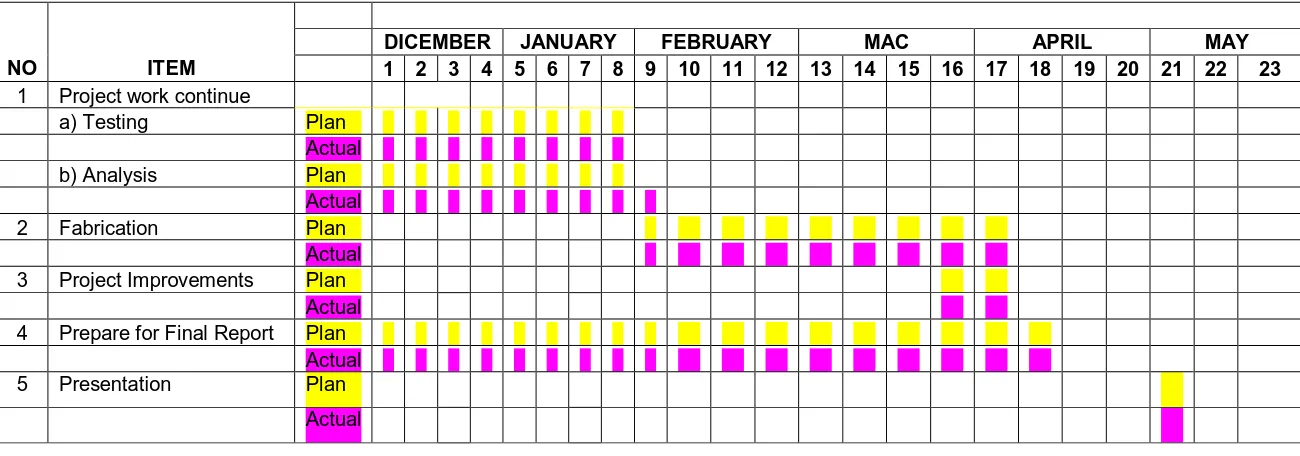
4 1.5 Gantt chat for PSM 1 and PSM 2
Figure 1.1 shows Gantt chat for PSM 1 and figure 1.2 shows Gantt chat for PSM 2.
Figure 1.2: Gantt chat for PSM 2
SCHEDULE PROJECT PSM 2: SITI UMI HANI BINTI MOHAMED (B050610187)
6
1.6 Project outline
Chapter 1
Describe the introduction of this project about the background of the study, problem
statement, project objective, scope of the project and Gantt chat for PSM 1 and PSM 11.
Chapter 2
Describe the fixtures system include the application of clamping, holding and
supporting. And study about milling machine and FEA analysis.
Chapter 3
Define the methodology in designing of long cylindrical workpiece fixtures and briefing
explanation of the each process.
Chapter 4
Describe the result. The data was analyzed using FEA tools to identify quality related
problems.
Chapter 5
Provide a general discussion on the design, the result of the study and implication of the
finding of the study.
Chapter 6
Define the conclusion on the study. Suggestions for future study are included in this
CHAPTER 2
LITERATURE REVIEW
This chapter will present the literature reviews relevant to this project. It includes
fixtures, conventional milling machine, the method of FEA (finite element analysis), and
the software used to design the new fixture. The entire thing in this chapter must be
considered to develop this project.
2.1 Fixture
A fixture is a manufacture tool that locates, holds, and supports the work securely so the
necessary machining operations can be performed. Fixtures hold the workpiece securely
in the correct position with respect to the machine or cutter during operation. There is
sometimes a provision in the fixtures for setting the tool with respect to the workpiece or
fixtures. But the tool is not guided as in a jig. And then the fixtures are often clamped to
the machine table (Joshi, 2003).
Fixtures should be securely fastened to the table of the machine upon which the work is
done. Through largely used on milling machines, fixtures are also designed to hold work
for various operations on most of standard machine tools. Beside that, the fixtures vary
in design from relatively simple tools to expensive, complicated devices. The fixtures
also help to simplify metalworking operations performed on special equipment