Master of Science in Mechanical Engineering
Faculty of Mechanical Engineering
MODELING AND ANALYSIS OF COMPOSITE HINGE FOR
AIRCRAFT SPOILER USING FINITE ELEMENT ANALYSIS
Wai Chee Mun
MODELING AND ANALYSIS OF COMPOSITE HINGE FOR AIRCRAFT SPOILER USING FINITE ELEMENT ANALYSIS
WAI CHEE MUN
A thesis submitted
in fulfillment of the requirements for the degree of Master of Science in Mechanical Engineering
Faculty of Mechanical Engineering
UNIVERSITI TEKNIKAL MALAYSIA MELAKA
DECLARATION
I declare that this thesis entitle “Modeling and Analysis of Composite Hinge for Aircraft
Spoiler using Finite Element Analysis” is the result of my own research except as cited in
the references. The thesis has not been accepted for any degree and is not concurrently
submitted in candidature of any other degree.
Signature : ...
Name : WAI CHEE MUN
APPROVAL
I hereby declare that I have read this dissertation/report and in my opinion this
dissertation/report is sufficient in terms of scope and quality as a partial fulfillment of
Master of Science in Mechanical Engineering.
Signature : ………...
Supervisor Name : AHMAD RIVAI
DEDICATION
ABSTRACT
This thesis is concerned with the modeling and analysis of a composite hinge bracket for Airbus A320 aircraft using Finite Element Method. The increasing demand of composite materials in aircraft structural design is due to the high strength and stiffness to weight ratio of the composite materials. The reduction in structural weight by the composite materials reduces the fuel consumption of the aircraft. Since the hinge bracket of the A320 aircraft is made of metallic materials, this research aims to redesign the hinge bracket with laminated composite plates. However, the design of structures with composites is not as easy as the design of metallic structures. Composites are heterogeneous and anisotropic in nature thus, complicating the structural analysis. The best practice of laminated composite design in the industry is simplified to accommodate the limitation of this research. The simplified design process is a simple three stages design process which focused on using Finite Element Anlysis for unidirectional laminated composite structural design. It begins with the determination of stress distribution in a metallic structure. The stress distribution allows the designer to identify areas of different stress distribution of the structure. Once the areas are identified, the direction of principle stresses is determine to decide on the fiber orientation and stacking sequence of the composite laminates for each area. Finally, the analysis of the laminated composite structure is carried out using Classical Laminate Plate theory and the structural integrity is accessed by the calculation of margin of safety. The simplified design process has been applied to redesign the metallic hinge bracket of A320 aircraft using IM7/8552 composite laminates. MSC Patran/Nastran and Abaqus CAE were used to carry out the finite element analysis of the hinge bracket. The composite hinge bracket has a margin of safety of 0.041. The weight savings by this composite hinge bracket is estimated to be 42.29 percent of the original metallic hinge bracket of A320. The success of this composite hinge design has proven that the simplified design process proposed in this research is indeed feasible for the purpose of preliminary design of laminated composite structures. The advantage of this simplified design process is that it approaches the design of composite structures in a systematic manner thus, allowing the identification of factors influencing the strength the laminated composite structural design. Since it is based on Finite Element Method, the results are at best approximations but sufficient to boost the level of confidence in the preliminary design stage.
ABSTRAK
Tesis ini adalah berkenaan dengan pemodelan dan analisis pendakap engsel komposit untuk pesawat Airbus A320 dengan menggunakan Kaedah Unsur Terhingga. Permintaan yang semakin meningkat daripada bahan komposit dalam reka bentuk struktur pesawat adalah disebabkan nisbah kekuatan dan kekakuan kepada berat bahan komposit yang tinggi. Pengurangan berat struktur oleh bahan-bahan komposit mampu mengurangkan penggunaan bahan api pesawat. Penyelidikan ini bertujuan untuk mereka bentuk semula pendakap engsel pesawat A320 dengan menggunakan plat komposit berlapis untuk menggantikan pendakap engsel lama pesawat A320 yang diperbuat daripada bahan logam. Walau bagaimanapun, reka bentuk struktur komposit tidak semudah reka bentuk struktur logam. Sifat bahan komposit yang anisotropik merumitkan analisis struktur. Amalan terbaik reka bentuk komposit berlapis dalam industri dipermudahkan untuk menampung had kajian ini. Proses reka bentuk yang dipermudahkan terdiri daripade tiga peringkat asas yang memberi tumpuan kepada menggunakan Analysis Unsur Terhingga untuk mereka bentuk struktur daripada plat komposit berlapis satu arah.. Ia bermula dengan penentuan agihan tegasan dalam struktur logam. Agihan tegasan membolehkan pereka mengenal pasti kawasan agihan tegasan yang berbeza dalam struktur. Sebaik sahaja kawasan dikenal pasti, arah tegasan prinsip digunakan untuk menentukan orientasi gentian dan susunan urutans lapisan komposit bagi setiap kawasan. Akhir sekali, analisis struktur komposit berlapis dijalankan dengan menggunakan teori Klasik lamina Plat dan integriti struktur diukur melalui pengiraan margin keselamatan. Proses reka bentuk yang dipermudahkan telah digunakan untuk mereka bentuk semula pendakap engsel logam pesawat A320 dengan menggunakan IM7/8552 komposit berlapis. MSC Patran/Nastran dan Abaqus CAE telah digunakan untuk menjalankan analisis unsur terhingga pendakap engsel tersebut. Pendakap engsel komposit mempunyai margin keselamatan 0.041. Penjimatan berat badan oleh pendakap engsel komposit ini dianggarkan 42.29 peratus daripada berat badan asal pendakap engsel logan pesawat A320. Kejayaan reka bentuk engsel komposit ini telah membuktikan bahawa proses reka bentuk yang mudah yang dicadangkan dalam kajian ini memang boleh digunakan untuk tujuan reka bentuk awal struktur komposit berlapis. Kelebihan model ini ialah ia membolehkan pengenalpastian faktor yang mempengaruhi kekuatan reka bentuk struktur komposit berlapis dalam proses reka bentuk struktur. Memandangkan ia adalah satu kaedah berdasarkan Kaedah Unsur Terhingga, keputusan analysis merupakan satu anggaran sahaja tetapi cukup untuk meningkatkan tahap keyakinan dalam reka bentuk dan pembuatan komposit.
ACKNOWLEDGEMENTS
I would like to thank Centre for Research and Innovation Management (CRIM) and
Faculty of Mechanical Engineering (FKM) Universiti Teknikal Malaysia Melaka for
funding this research through PJP/2012/FKM(18C)S1112 Research Fund and having
interest in this area of engineering. I hope that the contents of this thesis can benefit them
in designing and developing laminated composite structures in the future.
I would like to extend my appreciation to my supervisors, Associate Professor Ahmad
Rivai and Mr Omar Bapokutty, for their suggestions and guidance. Thank you, Mr. Omar,
for willing to join my research at a late notice.
I would also like to thank my parents, family members, friends who were involved directly
or indirectly in the completion of my thesis. Thank you for your morale support throughout
my graduate studies.
Last but not least, I would like to thank God for answering my prayers in my darkest time.
The completion of this thesis would not been possible without God’s will. I humbly thank
you for guiding and instilling faith in me.
TABLE OF CONTENTS
TABLE OF CONTENTS iv
LIST OF TABLES vi
LIST OF FIGURES viii
LIST OF APPENDIXES xi
LIST OF ABBREVIATIONS xii
LIST OF SYMBOLS xiv
LIST OF PUBLICATIONS xvi
CHAPTER
1.5 Overview of Thesis
2 LITERATURE REVIEW 6
2.1 Structural Design 6
2.1.1 The Design Process 7
2.1.2 Stress Analysis 9
2.1.3 Factor and Margin of Safety 11
2.1.4 Accuracy 13
2.1.5 Materials Selection 14
2.2 Composite 15
2.2.1 Composite in Aircraft Design 16
2.2.2 Laminated Composite 18
2.2.3 Mechanics of Laminated Composite 20
2.2.4 Failure Criteria of Laminated Composite 26
2.2.5 Composite Design Method 28
2.3 Finite Element Method and Analysis 29
2.3.1 Finite Element Procedures in Engineering Analysis 31 2.3.1.1 Verification and Validation of Simulation Models 33 2.3.2 Software Packages for Finite Element Analysis 36
2.3.2.1 MSC Patran & Nastran 37
2.3.2.2 Abaqus CAE 38
2.4 Chapter 2 Overview 39
3 METHODOLOGY 40
3.1 Working Method for Composite Design 40
3.2 Preliminary Analysis 42
3.3 Discretization 44
3.4 Composite Laminate Modeling 45
4 MODELING AND VERIFICATION 46
4.1 3D Hinge Bracket Modeling 46
4.2 2D Hinge Bracket Modeling 49
4.3 Verification of Modeling 52
5 RESULTS AND ANALYSIS 56
5.1 Preliminary Analysis of Metallic Hinge Bracket 56
5.1.1 Stress Analysis 57
5.2 Discretization of Composite Hinge Bracket 63
5.3 Original Composite Hinge Bracket Analysis 66
5.4 Modified Composite Hinge Bracket 75
5.5 Brief Economy Analysis 81
6 CONCLUSION AND RECOMMENDATIONS 82
6.1 Conclusion 82
6.2 Recommendations 84
REFERENCES 86
APPENDIXES 99
LIST OF TABLES
TABLE TITLE PAGE
4.1 Mechanical Properties of AA7075-T651 49
4.2 Mechanical Properties of IM7/8552 Lamina 51
4.3 Von Mises Stresses of W460x74 Beam 53
4.4 Deflection of W460x74 Beam at Different Beam Length 53
4.5 Elastic Properties of Each Ply 54
4.6 Ply by Ply Stress Results of Quasi-isotropic Laminate 55
5.1
Summary of Load Cases Considered in FEA for Spoiler Hinge
Bracket
56
5.2
Comparison of Von Mises Stresses at the Top Surface of the Right
Side of the Metallic Hinge Bracket
61
5.3
Composite Laminate Layup for Each Zone of A320 Composite Hinge
Bracket
64
5.4
Summary of Worst MS for Each Zone of the Composite Hinge
Bracket
68
5.5
Layer by Layer Longitudinal Stress of Zone A for Case of Spoiler
Close withNegative Wing Bending
70
5.6
Layer by Layer Longitudinal Stress of Zone A for Case of Spoiler
Open withPositive Wing Bending
70
5.7 Displacement Analysis of Zone A at Node 1 74
5.8
Composite Laminate Layup of the Modified Composite Hinge
Bracket
77
5.9
Summary of Worst MS by Zones for the Modified Composite Hinge
Bracket
79
5.10
Comparison of Worst MS at Each Zone between Original and
ModifiedComposite Hinge Bracket
80
5.11
Comparison of Weight Savings between Different Hinge Bracket
Designs
81
LIST OF FIGURES
FIGURE TITLE PAGE
1.1 Rolling Motion Cause by Deploying Right Spoiler 1
1.2 FACC Carbon Composite Center Hinge Fitting 2
1.3 Composite Structural Weight Development in Airbus 3
2.1 Design Model 7
2.2 Fiber Arrangement Patterns in a Lamina 18
2.3 Composite Laminate Drawing 19
2.4 Sign Convention of Positive and Negative Fiber Orientation 20
2.5 Finite Element Method Model 31
2.6 The Process of Finite Element Analysis 32
2.7 Verification and Validation Activities and Outcomes 34
3.1 Schematic Picture of Composite Working Method 40
3.2 Aero Shaped Segment 41
3.3 Unidirectional Laminated Composite Design Model 42
3.4 CAD Drawing of Airbus A320 Outer Hinge Bracket 43
3.5 Discretized Zones in Airbus A320 Hinge Bracket 44
4.1 CAD Model of A320 Hinge Bracket for 3D FE Modeling 46
4.2 Finite Element Modeling of 3D Hinge Bracket 47
4.3 CAD Model of A320 Hinge Bracket for 2D FE Modeling 49
4.4 Finite Element Modeling of 2D Hinge Bracket 50
4.5 W460x74 Beam 52
4.6 Composite Laminate Setup for Tension Coupon Test 54
5.1
Stress Distribution of Metallic Hinge Bracket for Case of Spoiler
Close
56
5.2
Stress Distribution of Metallic Hinge Bracket for Case of Spoiler
Open
56
5.3 Stress Concentration at Bolt Holes of Metallic Hinge Bracket 58
5.4
Stress Distribution for Metallic Hinge Bracket for Case of Spoiler
Close
59
5.5
Comparison of Stress Concentration at Lug of the Metallic Hinge
Bracket
60
5.6
Nodes Location at the Top Surface of the Right Side of the Hinge
Bracket
61
5.7
Comparison of Stresses Obtained by Nastran and Abaqus at the Top
Surface of the Sides of the Metallic Hinge Bracket
62
5.8
Comparison of Stresses between Six Different Load Cases at the Top
Surface of the Sides of the Metallic Hinge Bracket
62
5.9
Discretization of A320 Hinge Bracket by Areas of Different
Thickness
64
5.10
Discretization of 2D FE Model of A320 Hinge Bracket by Areas of
Different Stress Distribution and Laminate Thickness
64
5.11 Difference in Global Axis and Local Material Axis in Zone A 66
5.12
Comparison of Von Mises Stresses (MPa) between Metallic Hinge
Bracket and Composite Hinge Bracket for the Case of Spoiler Close 67
With negative Wing Bending
5.13
Comparison of Von Mises Stresses (MPa) between Metallic Hinge
Bracket and Composite Hinge Bracket for the Case of Spoiler Open
With Positive Wing Bending
67
5.14 Comparison between 3D and 2D FE Model of A320 Hinge Bracket 69
5.15 Laminate Stacking Sequence of Zone A 69
5.16 Left Side View of Zone A of the Composite Hinge Bracket 70
5.17
Average Longitudinal Stress in MPa of the Composite Laminate in
Zone A
72
5.18
Layer by Layer Analysis of Longitudinal Stress of Zone A of the
Composite Hinge Bracket for the Case of Spoiler Close with
Negative Wing Bending
72
5.19
Layer by Layer Analysis of Longitudinal Stress of Zone A of the
CompositeHinge Bracket for the Case of Spoiler Open with Positive
Wing Bending
73
5.20 Deformation of Composite Laminate in Zone A 74
5.21 Composite Hinge Bracket 75
5.22 Discretization of Modified Composite Hinge Bracket 76
5.23
Comparison of Von Mises Stresses between Original and Modified
Composite Hinge Bracket for the Case of Spoiler Close with
Negative Wing Bending
78
5.24
Comparison of Von Mises stresses between Original and Modified
CompositeHinge Bracket for the Case of Spoiler Open with Positive
Wing Bending
78
LIST OF APPENDIXES
APPENDIX TITLE PAGE
A Airbus A320 Original Hinge Bracket Drawing 99
B Airbus A320 Hinge Loads 100
C Selected Properties of Matrix and Fibrous Materials 102
D Hexcel Datasheet for HexPly 8552 Epoxy Matrix 103
E Calculation of IM7/8552 Lamina Properties 104
F Weight Calculation of Airbus A320 Hinge Bracket 106
G Mesh Refinement 110
H Calculation of Principle Stresses 113
LIST OF ABBREVIATIONS
1D - One dimensional
2D - Two dimensional
3D - Three dimensional
ASM - American Society for Metals
ASME - American Society of Mechanical Engineers
CAD - Computer Aided Design
CAM - Cylindrical Assemblage Model
CLT - Classical Laminate Theory
cm3 - Centimeter cube
DoFs - Degree of Freedoms
DTA - Damage Tolerance Analysis
etc. - et cetera
FAA - Federal Aviation Administration
FACC - Fischer Advanced Composite Components
FE - Finite Element
FEA - Finite Element Analysis
FEM - Finite Element Method
FPF - First ply failure
FRP - Fiber Reinforced Polymer
FS - Factor of Safety
g - Gram
g/cm3 - Gram per centimeter cube
GUI - Graphic-user interface
IBC - International Building Code
in - Inch
NASA - The National Aeronautics and Space Administration
PLM - Patran Laminate Modeler
PPF - Progressive ply failure
psi - Pounds per square inch
RBE - Rigid Body Elements
RF - Reserved Factor
RTM - Resin transfer moulding
UD - Unidirectional
VAC - Volvo Aero Corporation
V&V - Verification and validation
VV&A - Verification, validation and accreditation
LIST OF SYMBOLS
% - Percent
° - Degree
cm3 - Centimeter cube
g/cm3 - Gram per centimeter cube
Ɵ - Angle
Vf - Fiber volume fraction
Vm - Matrix volume fraction
Wf - Fiber weight fraction
Wm - Matrix weight fraction
Ρ - Density
ρc - Lamina density
ρf - Fiber density
ρm - Matrix density
E1 - Lamina longitudinal modulus
Ef - Fiber elastic modulus
Em - Matrix elastic modulus
v12 - In-plane Poisson’s ratio
vf - Fiber Poisson’s ratio
vm - Matrix Poisson’s ratio
E2 - Lamina transverse modulus
ζ - Empirical parameter
G12 - Lamina in-plane shear modulus
Gf - Fiber shear modulus
Gm - Matrix shear modulus.
G23 - Lamina out of plane shear modulus
σ1 - Maximum local stress along fiber direction
σ2 - Maximum local stress transverse to the fiber direction
τ12 - Maximum shear stress in the principal material direction
Fft - Fiber tensile strength
F1c - Lamina longitudinal compressive strength
F2t - Lamina transverse tensile strength
Fmt - Matrix tensile strength
F2c - Lamina transverse compressive strength
Fmc - Matrix compressive strength
F6 - Lamina in-plane shear strength
Fms - Matrix shear strength
ασ - Standard deviation of fiber misalignment
Vv - Void volume fraction
П - A constant with the value of 3.142
LIST OF PUBLICATIONS
Journal:
Putra, A., Rivai, A., Wai, C.M., and Muhammad, N., 2014. Preliminary Investigation on the Perforated Panel Mobility using Finite Element Method. Applied Mechanics and Materials, 471, pp.341 – 346.
Wai, C.M., Rivai, A., and Omar, B., 2013. Modeling Optimization Involving Different Types of Elements in Finite Element Analysis. IOP Conference Series: Materials Science and Engineering, 50 (1), pp. 1 – 8.
Wai, C.M., Rivai, A., and Omar, B., 2013. Effects of Elements on Linear Elastic Stress Analysis: A Finite Element Approach. International Journal of Research in Engineering and Technology (IJRET), 10 (2), pp.561 – 567.
Wai, C.M., Ahmad, R., and Omar, B., 2013. Design and Analysis of an Aircraft Composite Hinge Bracket using Finite Element Approach. Applied Mechanics and Materials (Accepted manuscript).
Putra, A., Cheah, Y.M., Muhammad, N., Rivai, A., and Wai, C.M., 2014. The Effect of Perforation on the Dynamics of a Flexible Panel. Advances in Acoustic and Vibration (Accepted manuscript).
CHAPTER 1
1 INTRODUCTION
1.1 Background
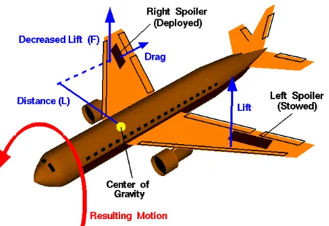
Commercial aircrafts, such as Airbus A380 and Boeing E787, have spoilers
attached to the top surface of their wings. Spoilers are plate like structures used to assist
the landing and descending of an aircraft from higher to lower altitude as well as generate
rolling motion of the aircraft (Dawson, 2006; NASA, 2010). Figure 1.1 shows the rolling
motion generated by deploying the right spoiler of an aircraft.
Figure 1.1 : Rolling Motion Cause by Deploying Right Spoiler (NASA, 2010)
As the name suggest, aircraft spoilers are used to “spoil” the airflow over the wing.
When both the spoilers are deployed, the drag increases while the lift decreases (Dawson,
2006). The decrease in the lift enables the aircraft to descend from a higher to lower
altitude and slow down before landing. Spoilers are also useful in assisting the breaking of
The upward and downward movements of the aircraft spoilers are made possible by
a set of hinges. A hinge is a mechanism which allows the rotational motion in one axis
(Leet et al., 2008). Hinges usually consists of two brackets. Some hinges have bearings
fitting to reduce frictional force between the pin and two brackets. The brackets of the
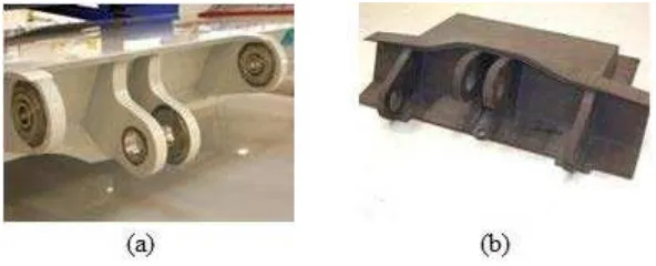
hinges are supportive structures which are usually made of metals. In 2006, Fischer
Advanced Composite Components (FACC) AG successfully designed a composite center
hinge fitting for Airbus, shown in Figure 1.2, by using resin transfer molding (RTM). The
composite hinge is said to be able to withstand 20 ton air load and save 25 percent in
weight per set of hinge (Dawson, 2006).
Figure 1.2 : FACC Carbon Composite Center Hinge Fitting (Dawson, 2006): (a) Metal Bushings and Bearings Installed in the Fitting Lugs; (b) Hinge Fitting Molded via RTM
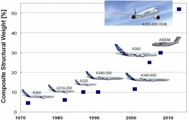
In aircraft construction, composites are more commonly used for secondary
structure, wings, fuselages, and even smaller parts such as spoilers (Dawson, 2006).
However, the use of composite materials in commercial aircraft has been increasing
exponentially since the last decade due to their capability in reducing the overall structural
weight of the aircraft effectively (Basavaraju, 2005; Mallick, 2007). Companies such as
Airbus and Boeing have been replacing their metallic aircraft parts with composite
materials. Figure 1.3 shows the composite structural weight development in Airbus
commercial aircrafts. Though the development of composites has mostly been derived
from military and The National Aeronautics and Space Administration (NASA) prototypes
(Cole, 2002), it is not too farfetch to say that there will be an all composite aircraft one day.
Figure 1.3 : Composite Structural Weight Development in Airbus (Bold, 2007)
1.2 Problem Statement
Existing hinges for aircraft spoilers, especially the old aircraft models, are mostly
made of metals. For example, the Airbus A320 aircraft spoiler hinges are still made of
metal. The replacement of the existing metallic hinges with composite materials may save
up quite a considerable amount of the hinges structural weight. The decrease in the aircraft
structural weight will reduce the fuel consumption of the aircraft. However, composite is
still considered new compared to the well established monolithic metals (Maligno, 2007;
Nguyen, 2010). Therefore, more information and a different approach to design composite
structure are required (Mallick, 2007). The industry has developed their own best practices
to design composite structures but the educational model flow to design composite
structures, especially laminated composite structures, is still lacking in the engineering
textbooks.