A STUDY ON FIBER GLASS COMPOSITE HOVERCRAFT HULL WITH DIFFERENT WALL THICKNESS USING FINITE ELEMENT ANALYSIS
By
MUHAMMAD AIMAN BIN AHMAD FOZI
Project report submitted to the Faculty of Engineering, University Putra Malaysia in fulfillment of the requirement for the degree of Master of
Innovation and Engineering Design
January 2012
© This
item
is protected
by original
copyright
ABSTRACT
Abstract of project report presented to the supervisor and examiners of University Putra Malaysia in fulfillment of the requirement for the degree of
Master of Innovation and Engineering Design
A STUDY ON FIBER GLASS COMPOSITE HOVERCRAFT HULL WITH DIFFERENT WALL THICKNESS USING FINITE ELEMENT ANALYSIS
By
MUHAMMAD AIMAN BIN AHMAD FOZI January 2012
Supervisor: Assoc. Prof. LT. Kol. (B) Mohamed Tarmizi Ahmad Department: Aerospace Engineering
Faculty: Engineering
Now days, the usage of fibre reinforce has tremendously give benefit to a weight reduction and enhancing the performance of a product. The design and development of this project consist of the study of the material used for the hull design which is a composite material known as fibre glass reinforced plastic. The benchmarking of the hull design used a previous design from universal hovercraft whereby the previous design was made from marine grade plywood. Some development and innovative changes have been made to the hull design by inserting inner structures to strengthen the hull by using fibre glass material.
This project will focus more on the analysis of the hull structure and construction using FRP composite. The analysis will use a 3D modeling data using CATIA and will be analyzed using CATIA /Abacus FEM method. Scale model will be done as an experimental study for the conceptual design and to
II
© This
item
is protected
by original
copyright
study the overall hovercraft design. The result will be used in order to optimize the structure design of the hovercraft hull.
In summary, from the project it shows that the composite is a unique material because the material properties are different from other standard material due to the ratio of the mixture between fiber and epoxy. The strength of material also changes due to the volume of the composite itself.
In conclusion, from the result of the FEA analysis the composite hull shows that the increasing thickness of the structure will affect the weight of the hull. As a trade-off in designing the hull, the weight is important for the performance of the hovercraft. From the FEA analysis, the result also shows that displacement is more accurate than Von Mises Stress in FEA analysis.
FEA analysis is a tool that can help in enhancing a product optimization and predict a failure for the designed part.
III
© This
item
is protected
by original
copyright
ABSTRAK
Abstrak laporan projek yang dikemukakan kepada penyelia dan para pemeriksa Universiti Putra Malaysia sebagai memenuhi keperluan untuk
ijazah Sarjana Inovasi Dan Kejuruteraan Rekabentuk
KAJIAN MENGENAI `HOVERCRAFT HULL` DARIPADA KOMPOSIT GENTIAN KACA DENGAN KETEBALAN STRUKTUR YANG BERBEZA
MENGGUNAKAN ANALISA UNSUR TERHINGGA Oleh
MUHAMMAD AIMAN BIN AHMAD FOZI Januari 2012
Penyelia: Prof. Madya LT. Kol. (B) Mohamed Tarmizi Ahmad Jabatan: Aeroangkasa
Fakulti: Kejuruteraan
Pada masa kini, penggunaan gentian kaca komposit telah memberikan banyak kelebihan terhadap pengurangan berat dan meningkatkan prestasi sesuatu produk. Rekebentuk dan pembangunan untuk projek ini merangkumi kajian terhadap bahan yang digunakan untuk pembuatan lantai hovercraft iaitu gentian kaca komposit. Penanda aras untuk projek ini adalah berasaskan rekabentuk hovercraft daripada Universal Hovercraft yang mana sebelum ini menggunakan papan lapis gred marin untuk komponen tersebut. Perubahan yang dilakukan adalah dengan menggantikan komponen tersebut dengan gentian kaca komposit dan struktur dalaman akan ditambah untuk menguatkan komponen tersebut.
Projek ini memberi fokus kepada analisa struktur rekaan komponen tersebut menggunakan analisa unsur terhingga. Analisa akan
IV
© This
item
is protected
by original
copyright
menggunakan model tiga dimensi yang dilukis menggunakan perisian Rekabentuk Berbantu Komputer 3 Dimensi. Analisa akan digunakan untuk mengoptimumkan rekabentuk komponen tersebut.
Secara ringkasnya, komposit gentian kaca adalah suatu bahan yang mempunyai sifat yang unik dan tidak sama seperti bahan lain yang mempunyai piawaian yang seragam. Nisbah dan kuantiti isipadu memainkan peranan dalam menentukan sifat sesuatu bahan komposit.
Kesimpulannya, penambahan ketebalan struktur akan mempengaruhi berat struktur tersebut dimana ini juga akan mempengaruhi prestasi komponen tersbut. Nilai pemindahan dalam analisa unsur tehingga juga didapati adalah lebih realistik daripada nilai tekanan Von Mises kerana ianya lebih stabil. Analisa unsur terhingga juga banyak membantu dalam proses mengoptimukan rekabentuk sebelum komponen itu dihasilkan secara realiti dan ini akan mejimatkan kos dan memberikan jangkaan ramalan kepada pereka mengenai prestasi produk yang dihasilkan.
V
© This
item
is protected
by original
copyright
ACKNOWLEDGEMENTS
This project thesis was done for the KAA5988 course in second semester of Masters of Innovation and Engineering Design at the Aerospace Department, University Putra Malaysia. It was continued to the third semester by the given period of time, Jan 2011 to Jan 2012, supervised by Assoc.
Prof. LT. Kol. (B) Mohamed Tarmizi Ahmad.
Through this work, I was given the opportunity, to design and develop a hovercraft hull based from the previous design guide from Universal Hovercraft handbook. The innovation process involves design a new structure, optimization of the structure and construction process of using fibre glass or Glass Reinforced Plastic (GRP) for the hull.
I am thankful that my study has been sponsored by the Malaysia Ministry of Higher Education (MOHE) which without that I would not be having been able to engage this project.
Special thanks go to the advisor, Assoc. Prof. Col. Tarmizi and Dr.
Rizal Zahari who has greatly assisted to finish my project and also to other lecturers that contribute in guiding to finish this project. In addition, I also want to address my appreciation to our colleagues that always stand for their help and support.
VI
© This
item
is protected
by original
copyright
APPROVAL
I certify that an Examination Committee has met on 19th January 2012 to conduct the final project presentation of Muhammad Aiman bin Ahmad Fozi on his Master Degree of Innovation and Engineering Design project entitled “A Study On Fiber Glass Composite Hovercraft Hull With Different Wall Thickness Using Finite Element Analysis” in accordance with the University Colleges Act 1971 and the Constitution of the University Putra Malaysia [P.U. (A) 106] 15 March 1998. The committee recommends that the student be awarded the degree of Master of Innovation and Engineering Design.
Members of the Examination Committee were as follows:
____________________
Assoc. Prof. LT. Kol. (B) Mohamed Tarmizi Ahmad Faculty of Engineering
University Putra Malaysia (Supervisor)
____________________
Assoc. Prof. LT. Kol. (B) Mohd Ramly Ajir Faculty of Engineering
University Putra Malaysia (Examiner 1)
____________________
Assoc. Prof. Dr. Abd. Rahim Abu Talib Faculty of Engineering
University Putra Malaysia (Examiner 2)
Dr. Rizal Zahari
Program Co-ordinator
Master of Innovation and Engineering Design Faculty of Engineering
University Putra Malaysia Date:
VII
© This
item
is protected
by original
copyright
DECLARATION
I hereby declare that the thesis is based on my original work accept for quotations and citations, which have been duly acknowledge. I also declare that is has not been previously or concurrently submitted for any other degree at UPM or other institutions.
MUHAMMAD AIMAN BIN AHMAD FOZI Date:
VIII
© This
item
is protected
by original
copyright
TABLE OF CONTENTS
Page ABSTRACT ... II ABSTRAK ... IV ACKNOWLEDGEMENTS ... VI APPROVAL ... VII DECLARATION ... VIII TABLE OF CONTENTS ... IX LIST OF TABLES ... XIII LIST OF FIGURES ... XIV LIST OF ABBREVATIONS ... XVI
CHAPTER 1 ... 0
INTRODUCTION ... 0
1.1 Project background ... 0
1.2 Rationales... 1
1.3 Objectives ... 1
CHAPTER 2 ... 3
LITERATURE REVIEW ... 3
2.1 Hovercraft theory... 3
2.2 Existing hovercraft ... 5
2.3 Patent search ... 7 IX
© This
item
is protected
by original
copyright
2.4 Universal Hovercraft – Hoverwing Flying Ground Effect ... 10
2.5 Comparison between Composite and Aluminium hull ... 13
2.6 Material (GRP & FRP) ... 20
2.6.1 Glass-reinforced plastic (GRP)... 20
2.6.2 Fibre Reinforced Plastics (FRP) ... 20
2.7 Conventional hull construction ... 24
2.8 Design and analysis tools ... 26
2.9 Stress Analysis ... 27
2.10 Factor of safety ... 28
2.11 Loadings for the hull ... 30
2.12 FEA (Finite Element Analysis) ... 31
2.13 CATIA FEA – Generative Structural Analysis ... 33
CHAPTER 3 ... 34
METHODOLOGY ... 34
3.1 Project Management ... 34
3.2 Flow of Design Process ... 35
3.3 Conceptual Design & Selection... 37
3.4 Mock-up (Crude model) ... 39
3.5 System boundary ... 40
3.6 Quality function deployment (QFD)... 42
3.7 Product trade-off ... 44
3.8 Geometry Construction ... 45 X
© This
item
is protected
by original
copyright
3.9 3D Modelling ... 47
3.10 Final design... 48
3.11 FEA analysis ... 49
3.11.1 Pre-processing ... 49
3.11.2 Solution ... 49
3.11.3 Post-processing ... 50
3.11.4 Changing design structure ... 50
3.12 Flow of FEA process ... 51
3.13 Preliminary Analysis ... 52
CHAPTER 4 ... 54
RESULTS AND DISCUSSION ... 54
4.1 Analysis Results ... 54
4.2 Meshing Convergence ... 56
4.3 Results comparison & discussion ... 58
CHAPTER 5 ... 60
5 SUMMARY, CONCLUSION AND RECOMMENDATIONS FOR FUTURE RESEARCH ... 60
5.1 Summary ... 60
5.2 Conclusion ... 61
5.3 Recommendations ... 61
REFERENCES ... 62
APPENDICES ... 63 XI
© This
item
is protected
by original
copyright
STUDENT BIODATA ... 69
XII
© This
item
is protected
by original
copyright
LIST OF TABLES
Table 1: Existing hovercraft in market (2011) ... 6
Table 2: Patent search of existing hull structure design ... 9
Table 3: Specifications of Hovercraft19XRW Hoverwing™ ... 13
Table 4: Comparison between Composite Fibre Reinforce Plastic (FRP) and Aluminium hull. ... 19
Table 5: FRP material properties ... 22
Table 6: Example of design and analysis tools ... 27
Table 7: Approximation of weight for components in the hovercraft ... 30
Table 8: Development using 3D software Catia V5r19 ... 39
Table 9: Analysis specification for numerical predictions ... 40
Table 10: Details of parameters, 60% s-glass fibre & 40% epoxy resin... 41
Table 11: Dependency of QFD criteria ... 43
Table 12: Mesh convergence study ... 56
Table 13: Analysis result of the variables thickness ... 58
XIII
© This
item
is protected
by original
copyright
LIST OF FIGURES
Figure 1: Hovercraft theory ... 3
Figure 2: Hovercraft 19XRW HoverwingTM... 10
Figure 3: Hull construction using plywood and sandwich techniques... 24
Figure 4: Subdivision of a plate into triangular elements... 31
Figure 5: Single degree of freedom at each grid point – truss ... 32
Figure 6: Two degree of freedom - membranes, plates and shell ... 32
Figure 7: Solid elements – thick plates, shell and solid media... 32
Figure 8: Layout of CATIA - Generative Structural Analysis ... 33
Figure 9: Project schedule management... 34
Figure 10: Flow of design process ... 36
Figure 11: Conceptual design using sketch and 3D software ... 37
Figure 12: Mock-up scale model studies ... 39
Figure 13: Quality Function Deployment ... 43
Figure 14: Geometry of the hull structure design ... 45
Figure 15: Part characteristic determine by moment inertia in CATIA... 46
Figure 16: 3D modelling using CATIA software ... 47
Figure 17: Final design of the hovercraft hull ... 48
Figure 18: Flow of FEA procedure ... 51
Figure 19: Clamp Position and Distributed Force ... 53
Figure 20: Close up area force applied ... 53
Figure 21: Part meshing for analysis ... 54
Figure 22: Deformation image after analysis computed ... 54
Figure 23: Von Mises Stress for the hull ... 55 XIV
© This
item
is protected
by original
copyright
Figure 24: Translational displacement vector ... 55 Figure 25: Displacement convergence study ... 57 Figure 26: Comparison of variables hull thickness ... 58
XV
© This
item
is protected
by original
copyright
LIST OF ABBREVATIONS
CAD Computer Aided Design FEM Finite Element Method CAS Computer Aided Styling CAE Computer Aided Engineering CAA Computer Aided Analysis CAM Computer Aided Manufacturing
3-D 3-Dimension
GSD Generative Shape Design FRP Fibre Reinforced Plastic GRP Glass Reinforced Plastic FEA Finite Element Analysis
CATIA Computer Aided Three-dimensional Interactive Application QFD Quality Function Deployment
XVI
© This
item
is protected
by original
copyright
CHAPTER 1
INTRODUCTION
1.1 Project background
The purpose of the project is to study on fiber glass composite hovercraft hull with different wall thickness using finite element analysis. This project involves design and develops a hovercraft hull using composite fibre glass material. Base on the data from the previous design, Hovercraft 19WX HoverwingTM from Universal hovercraft. From the literature study, the 3D model of the overall hovercraft had been done in CATIA software. For this particular project, it is mainly focusing on the effect of having different thickness of structure. Finite element analysis will be used to optimize the part.
Project also emphasize on the construction of the hull. Referring to the previous hull design that used marine grade plywood which is hardly to find in this country, the alternative material is used to suite the project. For the hull construction, FRP is the main case study for the part. Thus the design should consider about the design regulations for fibre glass mould. The new design of the hull still maintained the previous hull geometry, but major changes have been done to the structural design in order to optimize and strengthen the part.
© This
item
is protected
by original
copyright
1.2 Rationales
Rationale of this project is to replace the previous method of construction which used material that is hard to get in Malaysia. By replacing alternative material such as fiberglass, the construction and cost can be reduced. As a result of using fibre glass for the hull, the weight will be reducing compare to the previous one and strengthen the part. It is a hope that this project can be constructing locally. Therefore, the development of the part will be done using 3D modeling and also Finite Element Analysis to optimize the design before it goes to the construction process.
1.3 Objectives
The objectives of this project are:
1. To develop a new design hull using fiber glass composite (60% S- glass fibre and 40% epoxy resin) based on the Universal Hovercraft 19XRW HoverwingTM.
2. To investigate the effects of having different thickness of structure.
3. Using FEM analysis to investigate the maximum displacement of the different thickness of structure.
1
© This
item
is protected
by original
copyright
The design should be able to:
1. Produce and construct.
- The design of the hull should be able to construct using mould and fibre glass processes.
2. Comparable to existing hull.
- The new design using FRP material should be able to perform better and comparable to the previous hull design.
3. Structural optimization; Strength wise, able to withstand the maximum payload given.
- Using FEA analysis, the structural of the hull will be optimized to get the best capability of the design.
4. Reliability and Maintainability (R&M) - Simplicity and elegance
- Minimum number of parts
- Suitability for modular construction - Accessibility
- Sensibility adjust components
- Ease of adjustment( ease of maintenance)
2
© This
item
is protected
by original
copyright
CHAPTER 2
LITERATURE REVIEW
2.1 Hovercraft theory
Hovercraft was invented in 1956 by British Engineer, Christopher Cockerell. The vehicle also known as Air Cushion Vehicle (ACV) which is the vehicle literally floats on a cushion of air. Hovercraft basically powered by a fan mounted on its body, which provides the air lifting to the air cushion that enables the hovercraft to move effortless between land and sea (Spedding, 2001).
It is powered by a fan mounted on its body and it is supported by the cushion as it moves and enables the hovercraft to move effortlessly between land and sea. In June of 1959, his experimental hovercraft successfully crossed the English Channel between the ports of Doverand Calais.
However, the first hovercraft was actually launched in the Soviet Union long before Cockerell’s maiden voyage.
Hovercrafts are used throughout the world as a specialized transport.
The principle of how the hovercraft works shown in the figure 1.
Figure 1: Hovercraft theory
(Source: www.neoterichovercraft.com/general_info/hovercraft_principle.htm) 3
© This
item
is protected
by original
copyright
Hovercraft floats on a cushion of air that has been forced under the craft by a fan. This causes the craft to rise or lift. The amount of lift can range from 6" to 108" (152mm to 2,743mm) depending on the size of the craft. The amount of total weight that a hovercraft can raise is equal to cushion pressure multiplied by the area of the hovercraft. To make the craft function more efficiently, it is essential to limit the cushion air from escaping, so the air is contained by the use of a skirt. Skirts are made from fabric, which allows a deep cushion or clearance of obstacles, hovercraft skirts vary in style ranging from bags to cells to separate fingered sections called segments. Several hovercrafts utilize the segmented skirt system because each segment can deflect individually when passing over bumps so that very little lift air is lost on uneven terrain.
Once lifted or on cushion, thrust must be created to move the hovercraft forward. With many craft, this is generated by a separate engine from the one used to create the lift, but with some, the same engine is used for both. As the figure above indicates, the fan-generated air stream is split so that part of the air is directed under the hull for lift, while most of it is used for thrust.
After the hovercraft has lift and thrust, the maneuver system consists of rudders behind the fan, controlled by handlebars up front. Steering can also be controlled by the use of body weight displacement. The skills obtained upon practices. Some hovercraft offer an option which is reverse thrust buckets as another means of control.
4
© This
item
is protected
by original
copyright
2.2 Existing hovercraft
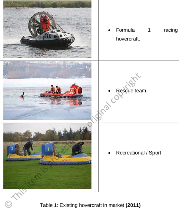
Hovercraft have been developed and used by military as a specialized transportation and for the past years publics start to use hovercraft as a personal and commercial transport in various sectors. Handling a hovercraft needs a lot of practices in order to understand the behavior of the vehicle because the hovercraft moves without frictions so it will be quite tricky to maneuver the hovercraft. Table 1 below shows some of the existing hovercraft.
Type of Hovercraft Description
• BHC SR.N4, the world's largest civilian hovercraft, can carry 254 passengers and 30 cars.
• Military
5
© This
item
is protected
by original
copyright
• Formula 1 racing hovercraft.
• Rescue team.
• Recreational / Sport
Table 1: Existing hovercraft in market (2011) (Source: www.worldhovercraftfederation.org/)
6
© This
item
is protected
by original
copyright
2.3 Patent search
Patents search and has been done to see the previous and current situation of the hovercraft. There are several patents of boats hull and the methods of how to strengthen the structure therefore several patents will be use as guidance for this project in order to get the solutions for the problem raised. The patents are shown in table 2:
Patent Description Image
Hull
Construction Inventor : Luther H.
Blount, 1 Shipyard La., Warren, R.I 02885 April,1981 Patent number : US 4365580
A composite hull construction. A rigid inner box like-structure of steel or aluminium is provided and acts as the main structural element of the hull, a rigid synthetic foam core intimately bonded to the exterior surfaces thereof. The exterior surface of the foam material is easily foam as desired to define the outer configuration of the hull and a layer of resin impregnated glass fibers is layed-up over the foam to provide a protective outer skin for the hull.
7
© This
item
is protected
by original
copyright