Mechanical Properties and Failure Analysis of Laminated Glass
Reinforced Composite with Various Gelcoat Thickness
Yuhazri M.Y.
a, Nilson G.C.H.
b, Haeryip Sihombing
cand Mohd Edeerozey Abd Manaf
dFaculty of Manufacturing, Universiti Teknikal Malaysia Melaka, Malaysia Hang Tuah Jaya, 76100, Durian Tunggal, Melaka, Malaysia
a[email protected], b[email protected], c[email protected], d[email protected]
Keywords: Gelcoat, Thickness, Brittle, Composite, Failure
Abstract. The aim of this study is to evaluate the mechanical properties and study the failure of laminated glass reinforced composite coated with gelcoat of different thickness. Firstly, the gelcoat was applied to the mould using brush and subsequently, glass fiber reinforced composite laminates were fabricated on it using vacuum bagging technique. The mechanical properties of the composites various were tested by using tensile and three-point flexural tests. The fracture behaviour of different gelcoat thickness was observed using scanning electron microscope (SEM) to determine the failure behaviour that occurred. The flexural test was performed in two ways, i.e., gelcoat layer facing top and facing down. For both flexural tests, composite coated with 0.30 mm thick of gelcoat shows the highest mechanical strength. Tensile test is useful to investigate the interfacial bonding in between gelcoat and laminate composite. The composite coated with 0.40 mm of gelcoat showed the highest tensile strength, an increase of 38 % compared to the uncoated composite. It was observed that an increase in gelcoat thickness increased the brittleness of the laminated composite. From the failure analysis, failures were caused by the delamination of matrix between the plies, while the gelcoat was still strongly bonded with composite laminate.
Introduction
A composite material is a macroscopic blending of two or more distinctive materials having a conspicuous interface between them. The strong adhesion between the fiber and the matrix will prompt to transverse failure of the matrix or the interface and interphase region. The main advantages of composite materials are high strength and stiffness, combined with low density aiming for weight diminishment in the finished part [1].
Børsting et al. [2] describes gelcoat as a material used to provide a high quality finish on the visible surface of the finished part of a fiber-reinforced composite material. The main focus is on the performance of gelcoat especially against harsh environment. It is important to achieve the proper thickness in stressed areas because thickness is a critical control point for crack prevention as mentioned by Lacovara [3]. The brittle gelcoat layer is due to excess of catalyst that cracks with little provocation. A more flexible gelcoat is not inclined to cracking; it is slanted toward premature colour degradation, loss of gloss, chalking or chemical attack.
Capela et al. [4] suggested that gelcoat surface layer influences the fatigue and impact loading performances. The composites coated with gelcoat layer were tested under compression loading showed a slight variation of the peak load and the elastic recuperation where a significant increased on maximum displacement and absorbed energy with the increasing of incident impact energy. In addition, McCrary-Dennis and Okoli [5] stated that the interface and interphase in between the gelcoat and laminate composite decides the mechanical performance of the composite. Eventually, the effective advancement of a composite material is characterized by the quality of interface that controls the reintroduction of stress into component at a damage site. As there is still no experimental research reported on the effect of gelcoat thickness on laminate structure and strength, this study is meant to explore in details as to gain deeper understanding on effect of different gelcoat thickness to laminated structure and strength.
Table 1 Technical data of polycor GP-H gelcoat. Viscosity 16,000 – 22,000 Thixotropic Index 6.0 – 8.0
Volatile Organic Compound 38.7 – 40.7% Flash Point 82 F
Weight per Gallon 9.95 – 10.25 Ibs Geltime With 1.8% MEKP 10.0 – 15.0 mins Lay-up Time 45 – 60 mins
Sag Resistance Good @ 20 mils wet
Fabrication Process. The process began with applying gelcoat layer to a clean plastic film by using hand brush as shown in Fig. 1(a). After every coating process, the coated layer was measured by using wet film thickness gauge as shown in Fig. 1(b) to ensure the gelcoat was spread evenly on the surface and then left for 10 minutes to cure. The steps were repeated until the desired gelcoat thickness was acquired. In order to prevent the external force from affecting the gelcoat thickness, each ply of glass fiber was wetted with resin before placed on the gelcoat. The samples were then wrapped according to the standard sequence of vacuum bagging technique using peel ply, perforated film, breather and mesh flow, and lastly covered by bagging plastic. The laminated composite was left for 24 hours to let it cure completely.
Fig. 1 (a) Applying gelcoat on film, (b) Thickness measurement of the coated layer.
Mechanical Testing. Tensile test was performed in accordance to ASTM D3039-00. The specimens were tested at a rate of 2 mm per minute. The interfacial bonding strength of various gelcoat thicknesses was determined from the stress strain curve. Flexural test was performed using the same machine according to ASTM D790-02. For the flexural test, samples were tested in two ways, i.e., coated surface facing the load (concave) and bare surface facing the load (convex) as shown in Fig. 2. The purpose was to monitor the failure behavior of gelcoat on both concave and convex face. A total of 8 samples were tested for each gelcoat thickness and the average value was recorded.
Fig. 2 Concave and convex face under three point flexural test.
Results and Discussions
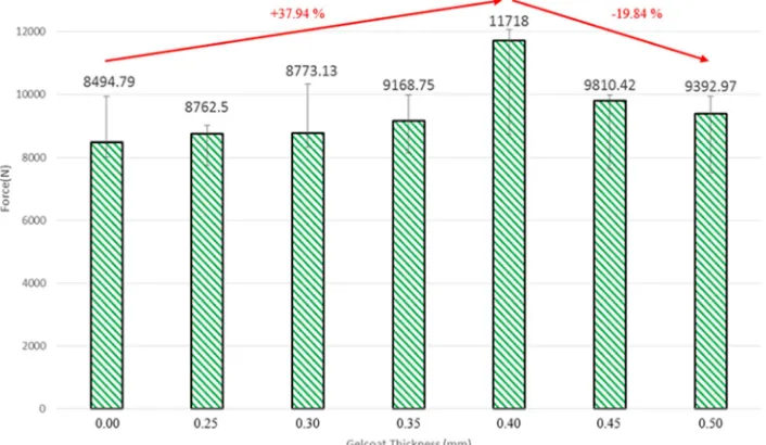
Tensile properties. Fig. 3 shows the average maximum force sustained by glass/polyester composite coated with gelcoat of different thickness. From the figure, tensile strength increases when gelcoat thickness is increased. The maximum tensile force obtained was 11718 N with the application of 0.40 mm thick gelcoat, an increase of 37.94% compared to the uncoated composite. However, tensile strength begins to decrease when the thickness is further increased to 0.45 mm and 0.50 mm where the value of maximum force at failure dropped almost 20%. This is due to increase in brittleness as the gelcoat and the resin-rich surface layer are very brittle and can subsequently fail catastrophically when overloaded [6].
Fig. 3 Graph of average maximum force sustained by glass/polyester composite coated with gelcoat of different thickness.
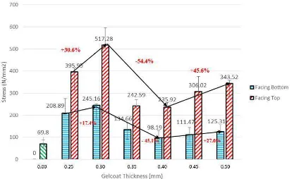
Flexural Strength. As shown in Fig. 4, coating of gelcoat improves the flexural strength of the laminated composite. The uncoated glass/polyester laminated composite is only able to sustain stress of 69.80 N/mm2. The maximum flexural strength is achieved with the gelcoat facing up (concavely bent), increased dramatically to about 517.28 N/mm2, which is more than 7-fold of
increase, after gelcoat of 0.30 mm thickness is applied. The value when the gelcoat is bent convexly (facing down) is slightly low at 245.16 N/mm2. The result proves that the application of gelcoat
Fig. 4 Flexural strength of glass/polyester composite coated with various thickness of gelcoat measured when the gelcoat bent convexly (left bars) and concavely (right bars).
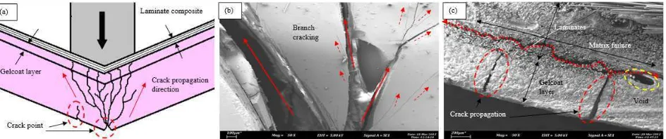
Failure Analysis. Fig. 5(a) shows the image of sample with 0.5 mm gelcoat thickness under flexural loading. It is clearly observed that a crack appear in the middle of the compression point and causes an obvious surface crack and propagates till the interface until the total fracture occur. Figure 5(b) shows the cross-sectional image of sample with 0.50 mm thick gelcoat that shows the presence of tiny voids near the interface between the gelcoat and laminates, which might explain the reason of interface cracking. The cracking propagates through the tiny voids which then cause reduction in mechanical strength to sustain the compression load.
Fig. 5 (a) Fracture image of the sample with 0.50 mm gelcoat thickness, (b) Tiny voids found at the interface between gelcoat layer and laminates.
From overall observation of the cracking images, the composites mostly show branch cracking pattern under convex bending as shown in Fig. 6(a). First, a crack starts at one at the edge of the sample and then propagates across the sample as the compression load increases. The crack continues till the interface between the gelcoat and laminates. Figure 6(b) and (c) show the SEM images of crack propagation in the coated laminated composite. The gelcoat layer is well bonded with the laminates because the crack propagates through the laminate not the interface section so it can be determined that it is a failure between the plies which is matrix failure.
Fig. 6 (a) Crack pattern in the gelcoat layer, (b) Branch cracking at gelcoat surface, (c) Matrix failure of laminates.
Conclusions
From the flexural test, composites coated with 0.30 mm thick gelcoat give the highest flexural strength. Gelcoat thickness of 0.40 mm is found to give the highest tensile force sustained, which is an increase of almost 38% compared to the uncoated composite. The optimum gelcoat thickness for glass/polyester laminated composite is in the range of 0.3 and 0.4 mm to yield the best mechanical properties. The most obvious failure is the brittle fracture of the gelcoat layer. The higher the gelcoat thickness, the more brittle the composites become. The delamination of matrix occurs within the four plies. From the SEM results, it was observed that the interfaces of gelcoat and laminate composite were strongly bonded and most final failures were caused by the delamination and voids in the interface zone that lowered the mechanical strength.
Acknowledgement
The author would like to thanks the Faculty of Manufacturing Engineering due to permission given to uses all the facilities in the Composite Engineering & Technology Laboratory. This research is funded by Fundamental Research Grant Scheme, FRGS/2013/FKP/TK04/02/4/F00164.
References
[1] F.C. Campbell, Structural Composite Materials (eBook), ASM International. The Materials Information Society, Ohio, 2010, pp. 1-31.
[2] D.A. Børsting, Q. Zhou, J.J. Van Der Zee, R. Rajamani, U.S. Patent, US 8808794 B2. (2014) [3] B. Lacovara, Get wise to gel coat cracks: characterizing crack defects, Convergent Composites, American Composites Manufacturers Association (2010) pp.1-8.
[4] C. Capela, J.M. Ferreira, H. Cravo, J.M. Costa, Fatigue and impact response of gel-coated glass mats/ polyester composites, J. Compos. Mater. 48 (2013) 1131-1137.
[5] M.C. McCrary-Dennis, O.I. Okoli, A review of multiscale composite manufacturing and challenges, J. Reinf. Plast. Compos. 31 (2012) 1687-1711.
[6] M.C. Chaturvedi, Welding and Joining of Aerospace Materials, Woodhead Publishing Limited, UK, 2012, pp. 298.
[7] P. Jawahar, K. Kanny, M. Balasubramanian, Influence of nanoclay addition on properties of unsaturated-polyester nanocomposite gel coat system, J. Polym. Eng. 29 (2009) 563–580.
[8] B. Muralidharan, J. Summerscales, Resin infusion under flexible moulding technique by in-mould gel coating using a flow medium, Indian J. Appl. Res. 3 (2013) 292-293.