PJP/2012/FKM (18C) S01112
COMPOSITE HINGE SPOILER
OMAR BIN BAPOKUTTY
RESEARCH VOTE NO: PJP/2012/FKM (18C) S01112
Fakulti Kejuruteraan Mekanikal Universiti Teknikal Malaysia Melaka
PJP/2012/FKM (18C) S01112
COMPOSITE HINGE SPOILER
OMAR BIN BAPOKUTTY
FAKULTI KEJURUTERAAN MEKANIKAL UNIVERSITI TEKNIKAL MALAYSIA MELAKA
ABSTRACT
COMPOSITE HINGE SPOILER
(Keywords : Composite hinge Bracket, Finite Element Analysis, Aircraft)
This research is concerned with the modeling and analysis of a composite hinge bracket for Airbus A320 aircraft using Finite Element Method. The increasing demand of composite materials in aircraft structural design is due to the high strength and stiffness to weight ratio of the composite materials. The reduction in structural weight by the composite materials reduces the fuel consumption of the aircraft. Since the hinge bracket of the A320 aircraft is made of metallic materials, this research aims to redesign the hinge bracket with laminated composite plates. However, the design of structures with composites is not as easy as the design of metallic structures. Composites are heterogeneous and anisotropic in nature thus, complicating the structural analysis. The best practice of laminated composite design in the industry is simplified to accommodate the limitation of this research. The simplified design process is a simple three stages design process which focused on using Finite Element Analysis for unidirectional laminated composite structural design. It begins with the determination of stress distribution in a metallic structure. The stress distribution allows the designer to identify areas of different stress distribution of the structure. Once the areas are identified, the direction of principle stresses is determine to decide on the fiber orientation and stacking sequence of the composite laminates for each area. Finally, the analysis of the laminated composite structure is carried out using Classical Laminate Plate theory and the structural integrity is accessed by the calculation of margin of safety. The simplified design process has been applied to redesign the metallic hinge bracket of A320 aircraft using IM7/8552 composite laminates. MSC Patran/Nastran and Abaqus CAE were used to carry out the finite element analysis of the hinge bracket. The composite hinge bracket has a margin of safety of 0.041. The weight savings by this composite hinge bracket is estimated to be 42.29 percent of the original metallic hinge bracket of A320. The success of this composite hinge design has proven that the simplified design process proposed in this research is indeed feasible for the purpose of preliminary design of laminated composite structures. The advantage of this simplified design process is that it approaches the design of composite structures in a systematic manner thus, allowing the identification of factors influencing the strength the laminated composite structural design. Since it is based on Finite Element Method, the results are at best approximations but sufficient to boost the level of confidence in the preliminary design stage.
Key Researchers: Omar bin Bapokutty
PM Ahmad Rivai
Table of Contents
1.0 INTRODUCTION 1
1.1 Background 1
1.2 Problem Statement 3
1.3 Objective 3
1.4 Scope 3
2.0 LITERATURE REVIEW 5
2.1 Composite 5
2.1.1 Laminated Composite 5
2.1.2 Mechanics of Laminated Composite 8
2.1.3 Failure Criteria of Laminated Composite 12
2.2 Design Process 13
2.2.1 Composite Design Method 15
2.2.2 Factor of Safety and Margin of Safety 16
2.3 Finite Element Method 17
3.0 METHODOLOGY 20
3.1 Working Method for Laminated Composite Structure 20
4.0 MODELING 25
4.1 3D Hinge Bracket 25
4.2 2D Hinge Bracket 27
4.3 Model Verification 30
5.0 RESULTS AND ANALYSIS 34
5.1 Preliminary Analysis of Metallic Hinge Bracket 34
5.2 Stress Analysis of Metallic Hinge 34
5.3 Discretization of Composite Hinge Bracket 40
5.4 Original Composite Hinge Bracket Analysis 42
5.5 Modified Composite Hinge Bracket 51
6.0 CONCLUSION AND RECOMMENDATIONS 57
6.1 Conclusion 57
LIST OF FIGURES
FIGURE TITLE PAGE
1.1 Rolling Motion Cause by Deploying Right Spoiler 1
1.2 FACC Carbon Composite Center Hinge Fitting 2
1.3 Composite Structural Weight Development in Airbus 2
2.1 Fiber Arrangement Patterns in a Lamina 6
2.2 Composite Laminate Drawing 7
2.3 Sign Convention of Positive and Negative Fiber Orientation 7
2.4 Design Model 14
2.5 Finite Element Method Model 17
2.6 The Process of Finite Element Analysis 18
3.1 Schematic Picture of Composite Working Method 20
3.2 Aero Shaped Segment 21
3.3 Unidirectional Laminated Composite Design Model 22
3.4 CAD Drawing of Airbus A320 Outer Hinge Bracket 22
3.5 Discretized Zones in Airbus A320 Hinge Bracket 23
4.1 CAD Model of A320 Hinge Bracket for 3D FE Modeling 25
4.2 Finite Element Modeling of 3D Hinge Bracket 26
4.3 CAD Model of A320 Hinge Bracket for 2D FE Modeling 28
4.4 Finite Element Modeling of 2D Hinge Bracket 29
4.6 Composite Laminate Setup for Tension Coupon Test 32
5.1 Stress Distribution of Metallic Hinge Bracket for Case of Spoiler Close 35
5.2 Stress Distribution of Metallic Hinge Bracket for Case of Spoiler Open 35
5.3 Stress Concentration at Bolt Holes of Metallic Hinge Bracket 36
5.4 Stress Distribution for Metallic Hinge Bracket for Case of Spoiler Close 36
5.5 Comparison of Stress Concentration at Lug of the Metallic Hinge Bracket 37
5.6 Nodes Location at the Top Surface of the Right Side of the Hinge Bracket 38
5.7
Comparison of Stresses Obtained by Nastran and Abaqus at the Top
Surface of the Sides of the Metallic Hinge Bracket
39
5.8
Comparison of Stresses between Six Different Load Cases at the Top
Surface of the Sides of the Metallic Hinge Bracket
39
5.9 Discretization of A320 Hinge Bracket by Areas of Different Thickness 40
5.10
Discretization of 2D FE Model of A320 Hinge Bracket by Areas of Different
Stress Distribution and Laminate Thickness
41
5.11 Difference in Global Axis and Local Material Axis in Zone A 42
5.12
Comparison of Von Mises Stresses (MPa) between Metallic Hinge Bracket
and Composite Hinge Bracket for the Case of Spoiler Close With negative
Wing Bending
43
5.13
Comparison of Von Mises Stresses (MPa) between Metallic Hinge Bracket
and Composite Hinge Bracket for the Case of Spoiler Open With Positive
Wing Bending
43
5.14 Comparison between 3D and 2D FE Model of A320 Hinge Bracket 45
5.15 Laminate Stacking Sequence of Zone A 45
5.16 Left Side View of Zone A of the Composite Hinge Bracket 45
5.18
Layer by Layer Analysis of Longitudinal Stress of Zone A of the Composite
Hinge Bracket for the Case of Spoiler Close with Negative Wing Bending
48
5.19
Layer by Layer Analysis of Longitudinal Stress of Zone A of the Composite
Hinge Bracket for the Case of Spoiler Open with Positive Wing Bending
49
5.20 Deformation of Composite Laminate in Zone A 50
5.21 Composite Hinge Bracket 51
5.22 Discretization of Modified Composite Hinge Bracket 52
5.23
Comparison of Von Mises Stresses between Original and Modified
Composite Hinge Bracket for the Case of Spoiler Close with Negative Wing
Bending
53
5.24
Comparison of Von Mises stresses between Original and Modified
Composite Hinge Bracket for the Case of Spoiler Open with Positive Wing
Bending
LIST OF TABLES
TABLE TITLE PAGE
4.1 Mechanical Properties of AA7075-T651 27
4.2 Mechanical Properties of IM7/8552 Lamina 30
4.3 Von Mises Stresses of W460x74 Beam 31
4.4 Deflection of W460x74 Beam at Different Beam Length 31
4.5 Elastic Properties of Each Ply 33
4.6 Ply by Ply Stress Results of Quasi-isotropic Laminate 33
5.1 Summary of Load Cases Considered in FEA for Spoiler Hinge Bracket 34
5.2
Comparison of Von Mises Stresses at the Top Surface of the Right Side of
the Metallic Hinge Bracket
38
5.3
Composite Laminate Layup for Each Zone of A320 Composite Hinge
Bracket
41
5.4 Summary of Worst MS for Each Zone of the Composite Hinge Bracket 44
5.5
Layer by Layer Longitudinal Stress of Zone A for Case of Spoiler Close with
Negative Wing Bending
46
5.6
Layer by Layer Longitudinal Stress of Zone A for Case of Spoiler Open with
Positive Wing Bending
47
5.7 Displacement Analysis of Zone A at Node 1 50
5.8 Composite Laminate Layup of the Modified Composite Hinge Bracket 52
5.9 Summary of Worst MS by Zones for the Modified Composite Hinge Bracket 54
Composite Hinge Bracket
1.0 INTRODUCTION
1.1 Background
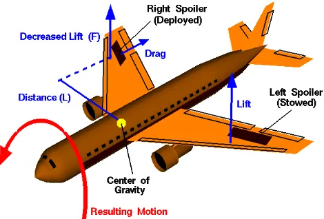
Commercial aircrafts, such as Airbus A380 and Boeing E787, have spoilers attached to the top surface of their wings. Spoilers are plate like structures used to assist the landing and descending of an aircraft from higher to lower altitude as well as generate rolling motion of the aircraft (Dawson, 2006; NASA, 2010). Figure 1.1 shows the rolling motion generated by deploying the right spoiler of an aircraft.
Figure 1.1 : Rolling Motion Cause by Deploying Right Spoiler (NASA, 2010)
As the name suggest, aircraft spoilers are used to “spoil” the airflow over the wing. When both the spoilers are deployed, the drag increases while the lift decreases (Dawson, 2006). The decrease in the lift enables the aircraft to descend from a higher to lower altitude and slow down before landing. Spoilers are also useful in assisting the breaking of the aircraft on the runway (NASA, 2010).
As the name suggest, aircraft spoilers are used to “spoil” the airflow over the wing. When both the spoilers are deployed, the drag increases while the lift decreases (Dawson, 2006). The decrease in the lift enables the aircraft to descend from a higher to lower altitude and slow down before landing. Spoilers are also useful in assisting the breaking of the aircraft on the runway (NASA, 2010).
The upward and downward movements of the aircraft spoilers are made possible by a set of hinges. A hinge is a mechanism which allows the rotational motion in one axis (Leet et al., 2008). Hinges usually consists of two brackets. Some hinges have bearings fitting to reduce frictional force between the pin and two brackets. The brackets of the hinges are supportive structures which are usually made of metals. In 2006, Fischer Advanced
Composite Components (FACC) AG successfully designed a composite center hinge fitting for Airbus, shown in Figure 1.2, by using resin transfer molding (RTM). The composite hinge is said to be able to withstand 20 ton air load and save 25 percent in weight per set of hinge (Dawson, 2006).
Figure 1.2 : FACC Carbon Composite Center Hinge Fitting (Dawson, 2006): (a) Metal Bushings and Bearings Installed in the Fitting Lugs; (b) Hinge Fitting Molded via RTM
In aircraft construction, composites are more commonly used for secondary structure, wings, fuselages, and even smaller parts such as spoilers (Dawson, 2006). However, the use of composite materials in commercial aircraft has been increasing exponentially since the last decade due to their capability in reducing the overall structural weight of the aircraft effectively (Basavaraju, 2005; Mallick, 2007). Companies such as Airbus and Boeing have been replacing their metallic aircraft parts with composite materials. Figure 1.3 shows the composite structural weight development in Airbus commercial aircrafts. Though the development of composites has mostly been derived from military and The National Aeronautics and Space Administration (NASA) prototypes (Cole, 2002), it is not too farfetch to say that there will be an all composite aircraft one day.
Figure 1.3 : Composite Structural Weight Development in Airbus (Bold, 2007)
1.2 Problem Statement
Existing hinges for aircraft spoilers, especially the old aircraft models, are mostly made of metals. For example, the Airbus A320 aircraft spoiler hinges are still made of metal. The replacement of the existing metallic hinges with composite materials may save up quite a considerable amount of the hinges structural weight. The decrease in the aircraft structural weight will reduce the fuel consumption of the aircraft. However, composite is still considered new compared to the well established monolithic metals (Maligno, 2007; Nguyen, 2010). Therefore, more information and a different approach to design composite structure are required (Mallick, 2007). The industry has developed their own best practices to design composite structures but the educational model flow to design composite structures, especially laminated composite structures, is still lacking in the engineering textbooks.
1.3 Objective
The objectives of this study are:
a) To redesign the existing metallic hinge of aircraft A320 spoilers with a laminated composite hinge bracket by using Finite Element Analysis (FEA) approach.
b) To simplify and propose a unidirectional (UD) laminated composite design process based on the best practices in the industry to access the structural integrity of laminated composite structures.
1.4 Scope
a) Redesign of Airbus A320 hinge for spoilers. The original design of Airbus A320 hinge bracket is maintained but the material is substituted with suitable laminated composite plates. The redesign of the geometry of the hinge is only carried out if necessary.
b) Composite design is carried out using the Classical Laminate Theory (CLT) only. Laminated composites used are limited to unidirectional tape of fiber reinforced polymers qualified for construction of aircraft components which are obtained through literatures.
c) Linear elastic static analysis of the composite hinge using FEA softwares, MSC Patran, MD Nastran and Abaqus CAE. The study of FEM is only limited to the usage of commercial FEA softwares. The research does not include the development of
additional FEA software tools, algorithms or any of its kind. FEA is carried out at component level only.
2.0 LITERATURE REVIEW
2.1 Composite
A composite is an engineered material made of at least two distinct materials which are combined at macroscopic level. The constituents of the composite material can still be distinguished from one another (Gurdal et al., 1999; Srinivasan, 2009; Barbero, 2010). The two constituents which made up the composite material are known as matrix and reinforcement. The matrix is a material which envelops the reinforcement protecting the reinforcement from the environment. The reinforcement, on the other hand plays an important role in providing structural strength to the composite (Mallick, 2007). Matrices are actually weak materials but capable of binding the reinforcements together and securing them in their positions (Kaw, 2006). The bonding between the matrix and the reinforcement enables the matrix to transfer and distribute loads evenly to the reinforcements. The matrix also serves other purposes such as improving the impact, fracture and fatigue resistance of the composite (Pandey, 2004).
Generally, composites are classified by the types of matrix material or the geometry of the reinforcement. There are four types of matrices which are metal, polymer, ceramic, and carbon matrix (Barbero, 2010) while there are three types of reinforcement including fiber, flake, and particulate (Pandey, 2004; Kaw, 2006). For example, fiber reinforced polymer (FRP) is composite which consist of a polymer matrix and fiber reinforcement.
Composites nowadays are being utilized in a variety of commercial and industrial products. Its original application is being expanded from the field of spacecraft and aircraft (Haddadpour et al., 2008) to other fields such as automotive (Fuchs et al., 2008), sporting goods, and infrastructure (Vaidya et al., 2006; Ellobody, 2011). This owes to the composite high strength and stiffness to weight ratio properties (Pandey, 2004). Composites are capable of providing the same amount of strength as monolithic metals but with lower density. Other attractive attributes of composites include low thermal conductivity and coefficient of thermal expansion, improved corrosion, and many more (Kaw, 2006).
2.1.1 Laminated Composite
Laminated composite is one of the few forms of fiber reinforced composites. It is made up of a few thin layers of fundamental building block called lamina or ply. A lamina is a composite material in the form of a thin sheet. It consists of bundles of fibers hold together by a homogeneous matrix (Grandt, 2004). The fibers can be continuous or discontinuous and
are usually circular in shape with typical radii of 0.005 mm to 0.05 mm. Continuous fibers can be in the form of UD tape or woven fabric. The fibers of UD tape are aligned along the length of the tape while the fibers of fabric are usually woven in two or more directions with designated patterns (Gurdal et al., 1999; Reddy, 2004; Barbero, 2010). Figure 2.1 shows the different types of lamina based on the orientation of fibers.
Figure 2.1 : Fiber Arrangement Patterns in a Lamina (Gurdal et al., 1999)
A laminate is formed from several laminas stacked up layer by layer to achieve the desired thickness of a structure. The laminas may vary in terms of material, fiber orientation, and thickness. The sequence of the layers in a laminate is called the stacking sequence of lamination scheme. The lamination scheme and material properties of individual lamina provide an added flexibility to the design of laminated composite structures (Reddy, 2004). This flexibility, however, comes with a tradeoff. Design of laminated composite structures requires not only technical drawings describing the geometry of the structure but also drawings that describe the lamination scheme of the composite laminate. An example of the composite laminate drawing is shown in Figure 2.2.
A standard notation comes along with the drawing to describe the lamination scheme. The standard notation for laminate design is derived from the most traditional manufacturing process of laminated composite, which is the hand lay-up process. The first ply is designed to be the most bottom ply of the laminate. The lamina is then added layer by layer according to the lamination scheme to produce the laminate. Take an example of the laminate shown in Figure 2.2.
Figure 2.2 : Composite Laminate Drawing (MSC, 2010)
The standard laminate notation is [0/-45/0/90/0/45]. The first layer of the laminate has an orientation of 0 degree, followed by the second, third, fourth, fifth, and sixth layer having fiber orientation of -45, 0, 90, 0, and +45 degree respectively. The angle ply combinations of [+θ/-θ] can be simplified as [±θ]. Abbreviation notation is also used to shorten long lamination scheme. A subscript (S) and (T) are used to specify symmetric and total laminate sequence. A number subscript is used to indicate a repeating pattern. For example, the laminate notation [±45/±45]S can also be written as [(±45)2]S (Gurdal et al., 1999; Barbero, 2010).
The angle of the fiber orientation is determined through the Right Hand Rule. The thumb represents the thickness direction while the curl of the fingers indicates the positive angle from the x-direction to the y-direction. The orientation of the fibers in each ply as they relate to the global coordinate system can be seen in Figure 2.3. The thickness direction is in the positive global z-direction which is pointing out of the laminate. The 1-direction and 2-direction are the laminate longitudinal and transverse directions. The coordinate system based on these directions is known as local coordinate system.
Figure 2.3 : Sign Convention of Positive and Negative Fiber Orientation (Staab, 1999)
2.1.2 Mechanics of Laminated Composite
Laminated composite, like every other composites, are heterogeneous and anisotropic in nature. Therefore, unlike conventional homogeneous isotropic metallic material, the study of the mechanics of laminated composite is separated into two parts, which are micromechanics and macromechanics.
Micromechanics is the study of the relationship between the individual properties of fiber and matrix in a lamina. It is useful in the prediction of mechanical behavior of a lamina such as stiffness and strength when subjected to static loads (Niu, 2010; Reddy, 2004; Barbero, 2010). A typical lamina with UD fiber is treated as an orthotropic material which is characterized by five stiffness properties. The five properties are longitudinal elastic modulus, transverse elastic modulus, in-plane Poisson’s ratio, in-plane shear modulus and out of plane Poisson’s ratio (Barbero, 2010).These orthotropic properties are obtainable though theoretical calculations or experimental methods.
It is assumed that a lamina is made up of only fiber and matrix and the total volume of the lamina is assumed to be 1. The fiber and matrix volume fraction are calculated using the following formula (Barbero, 2010):
�� =������������������������ (4)
�� =������������������������� (5)
where, Vf is the fiber volume fraction and Vm is the matrix volume fraction.
Alternatively, one can also determine the amount of fiber and matrix in a lamina by weight. Equations (6) and (7) are used to calculate the fiber and matrix weight fractions while Equation (8) is used to calculate the density of the lamina (Barbero, 2010):
��= ����ℎ����������ℎ�������� (6)
�� =����ℎ������������ℎ������� (7)
�� =����+���� (8)
where, Wf is the fiber weight fraction Wm is the matrix weight fraction,
ρc is the lamina density, ρf is the fiber density, ρm is the matrix density.
The use of Equation (8) is with the assumption that no void exist in the lamina. However, in actual case, void exists due to manufacturing processes. Therefore, the calculated lamina density may differ from the experimental lamina density. The experimental lamina density can be obtained using ASTM D2734 (Barbero, 2010).
The lamina longitudinal modulus and in-plane Poisson’s ratio is calculated using Rules of Mixtures (Barbero, 2010):
�1 =����+���� (9)
�12 =����+���� (10)
where, E1 is the lamina longitudinal modulus, Ef is the fiber elastic modulus,
Em is the matrix elastic modulus, v12 is the in-plane Poisson’s ratio, vf is the fiber Poisson’s ratio, vm is the matrix Poisson’s ratio.
The lamina transverse modulus is obtained using Halpin-Tsai formula (Barbero, 2010):
�2 = ���1+���1−����� (11)
� =�����⁄���−1
�⁄���+� (12)
where, E2 is the lamina transverse modulus and ζ is an empirical parameter usually given the value of 2 for the case of circular or square fibers.
The lamina in-plane and out of plan shear modulus are calculated using cylindrical assemblage model (CAM) and semi-empirical stress partitioning parameter technique respectively (Barbero, 2010):
�12 =����1+��1−���+�1−������⁄ ���
��+�1+������⁄ ��� � (13) �23= ���4�1−����+���+��4��1−�����⁄ ���� (14)
�4 =3−4�4�(1−�+����)⁄ ��� (15)
where, G12 is the lamina in-plane shear modulus, G23 is the lamina out of plane shear modulus. Gf is the fiber shear modulus,
Gm is the matrix shear modulus.
The prediction of lamina strength by micromechanics, however, is not as accurate as its prediction of lamina stiffness. It is best to obtain the strength of unidirectional lamina through experimental test. However, due to constraint of cost and time, fabrication and testing of lamina strength is usually impossible. Therefore, micromechanics are used as rough estimate for the strength of UD lamina. Though the calculated strength of lamina is far from accurate, it is sufficient as estimation for preliminary design. Equations (16) – (20) are used to compute the longitudinal tensile strength, longitudinal compressive strength, transverse tensile strength, transverse compressive strength, and in-plane shear strength of a lamina respectively (Barbero, 2011):
�1� =������+���⁄ ���� 1− ���� (16)
�1� =�12(1 + 4.76�)−0.69 (17)
�2� = ������1 +���− ���� �1−������ (18)
�2� = ������1 +���− ���� �1−���
��� (19) �6 = ������1 +���− ���� �1−���
��� (20) � =�12��
�6 (21)
�� = 1− ���1−�4��
�� (22)
where, F1t is the lamina longitudinal tensile strength, Fft is the fiber tensile strength,
F1c is the lamina longitudinal compressive strength, F2t is the lamina transverse tensile strength,
Fmt is the matrix tensile strength,
F2c is the lamina transverse compressive strength, Fmc is the matrix compressive strength,
F6 is the lamina in-plane shear strength, Fms is the matrix shear strength,
� is a dimensionless number,
ασ is the standard deviation of fiber misalignment, Vv is the void volume fraction,
П is a constant with the value of 3.142.
The use of micromechanics, however, is limited to the following assumptions (Reddy, 2004):
a) The bonding between fibers and matrix of a lamina is without any flaw. b) Fibers are uniformly distributed without any misalignments.
c) No residual stresses as well as flaws in the matrix such as voids or microcracks. d) The individual properties of fibers and matrix obey Hooke’s Law and are isotropic. e) Loads are applied parallel or perpendicularly to the fiber direction.
Macromechanics, on the other hand, involves the study of the mechanical behavior of a laminate based on the behavior of a lamina such as fiber orientations, lamina thickness and many more. It determines the relationship between the properties of the lamina and the properties of the laminate by assuming that each lamina is homogeneous and orthotropic (Niu, 2010; Reddy, 2004; Barbero, 2010).The macromechanics formulas are incorporated in numerical analysis such as FEA of composite structures. They are rarely used in hand calculation as they are long and tedious. Most engineering textbooks, such as those written by Gurdal et al. (1999), Reddy (2004) and Barbero (2010) provide detail explanation of the derivation of these formulas.
The orthotropic behavior of lamina allows the lamina to have high tensile and compressive strengths in the direction parallel to the fiber orientation. Therefore, fibers in a lamina are orientated in the direction of the applied load and the laminas are stacked up to provide adequate stiffness and strength to the laminate. Laminated composite allows the optimization of material design but at the same time induced a complicated stress analysis.
One of the composite laminate theories used for the analysis of laminated composite plates is the CLT, which is an extension of the Kirchhoff plate theory to laminated composite plates. Kirchhoff theory assumed that the deformation of a plate is due to bending and in-plane stretching only by neglecting both transverse shear and transverse normal effects (Reddy, 2004). The plate is assumed to have negligible thickness. Therefore, this assumption is only applicable to thin plates in which the thickness is very small compared to the length and width. This method allows the simplification of a three dimensional (3D) problem to a two dimensional (2D) problem. Most analyses of laminated composite plates are based on CLT as it is less complicated and the solution provides a good estimate. However, the prediction of CLT for thick composite laminates is inaccurate as the thickness cannot be neglected. Thick laminated composite plates can be analyzed using 3D elasticity theory (Reddy, 2004).
2.1.3 Failure Criteria of Laminated Composite
Failure in a laminated composite can be due to fiber breaking, matrix cracking, matrix cracking, fiber debonding, delamination and many others. It is impossible to consider all the failure modes into the design of laminated composite. Therefore, empirical, lamina failure criteria are used to predict the failure of a laminate. These failure criteria are modified from the failure criteria used in the design of metallic structures because laminated composites are heterogeneous and anisotropic in nature. The stress analysis of laminated composites using CLT is used together with these failure theories to determine the strength of laminated composite (Gurdal et al., 1999; Barbero, 2010).
Lamina failure criteria are equations formulated based on experimental data of failure of a lamina. Usually, experiment is carried out on a single unidirectional lamina until the lamina fails. The experimental data obtained is then used to adjust the lamina failure criteria so that it is usable to predict the failure of different laminated composites. These equations are useful when experimental data are not available for the design of laminated composite structure (Barbero, 2010).
One of the useful lamina failure criteria is the Maximum Stress Criteria. The Maximum Stress Criterion states that failure in a 2D orthotropic lamina occurs if any of the following is violated (Gurdal et al., 1999; Barbero, 2010; Gibson, 2012):
�1� <�1 < �1� (23)
�2� < �2 <�2� (24) |�12| <�6 (25)
where, σ1 is the maximum local stress along the fiber direction,
σ2 is the maximum local stress transverse to the fiber direction, τ12 is the maximum shear stress in the principal material direction.
Other failure criteria used to predict the failures of laminated composites are Maximum Strain Criterion, Tsai-Hill Criterion, Tsai-Wu Criterion and many more. The maximum stress criterion has the advantage of predicting the failure of a laminated composite with the least information required. Only five composite strength values, which are longitudinal tensile strength, longitudinal compressive strength, transverse tensile strength, transverse compressive strength, and in-plane shear strength, are required. The rest of the criterion, however, requires additional material information such as bonding strength and many more (Gurdal et al., 1999; Gibson, 2012).
The theories of failure criteria of laminated composites are limited to the prediction by first ply failure (FPF) only. FPF states that the failure of a laminate is govern by the first failure in any ply which constitutes the laminate. However, a laminate does not fail completely if one of its ply fails since a laminate is made of several plies. The stresses will be distributed to other plies, if local failure occurs, until those layers fail completely. This type of laminated composite failure analysis is known as progressive ply failure (PPF) analysis. The failure criteria are unable to predict the stress redistribution to other plies once a ply fails. Therefore, PPF can only be analyzed experimentally (Gurdal et al., 1999; Barbero, 2010).
2.2 Design Process
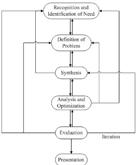
The design of an engineering structure or product in the industry begins with the identification of a need and proceeds through different phases of activity called the design process. Figure 2.1 shows the common steps in the design process taught in the academics.
These steps can be found in most engineering textbooks. They may vary in terms of sequence depending on the type of product design. It is more of a generalized methodology for the purpose of design process implementation (Wadhwa and Jolly, 2007; Babu and Srithar, 2010).
Figure 2.4 : Design Model (Babu and Srithar, 2010)
Although the design model in Figure 2.4 provides a good introduction to the design process, the actual design process in the industry is far more sophisticated. The complete design process, from the beginning of a new product design to the successful production of the new product, can be generally discussed in four arbitrary phases, which are preliminary design, intermediate design, detail design and lastly, development and field service (Norton, 2006; Collins et al., 2010).
The initial phase of design process is also known as preliminary design where the identification of the need to design and conceptual design is generated. The definition of conceptual design varies between engineering design textbooks. Some defined it as a step in the preliminary design phase which includes familiarization with the problem and generation of a variety of solutions to solve the problem (Wadhwa and Jolly, 2007). Other textbooks defined conceptual design as the preliminary design phase itself, which encompasses of