FACULTY OF INFORMATION AND COMMUNICATION
TECHNOLOGY
LOGICAL APPROACH: CONSISTENCY RULES BETWEEN
ACTIVITY DIAGRAM AND CLASS DIAGRAM
NORAINI BINTI SULAIMAN
MASTER OF COMPUTER SCIENCE (SOFTWARE ENGINEERING
AND INTELLIGENCE)
Faculty of Information and Communication Technology
LOGICAL APPROACH: CONSISTENCY RULES
BETWEEN ACTIVITY DIAGRAM AND CLASS
DIAGRAM
Noraini Binti Sulaiman
Master of Computer Science (Software Engineering and Intelligence)
LOGICAL APPROACH: CONSISTENCY RULES BETWEEN ACTIVITY DIAGRAM AND CLASS DIAGRAM
NORAINI BINTI SULAIMAN
A project submitted
in fulfillment of the requirements for the degree of Master of Computer Science (Software Engineering and Intelligence)
Faculty of Information and Communication Technology
UNIVERSITI TEKNIKAL MALAYSIA MELAKA
DECLARATION
I declare that this project entitled “Logical Approach: Consistency Rules between Activity Diagram and Class Diagram” is the result of my own research except as cited in the references. The thesis has not been accepted for any degree and is not concurrently submitted in candidature of any other degree.
APPROVAL
I hereby declare that I have read this report and in my opinion this report is sufficient in terms of scope and quality as a partial fulfillment of Master of Computer Science (Software Engineering and Intelligence).
DEDICATION
I sincerely dedicate this thesis to my beloved parents, Haji Mat Nasir and Hajah Nik Azmani, who supported me each step of the way.
ABSTRACT
Requirements validation especially models validation has gained quite an interest from a lot of researchers. The research regarding the consistency checking is proliferating from time to time. Several of techniques, approaches and methods have been proposed to cater the issues of requirements inconsistency especially in models validation. UML modelling has been used widely in software development industry. The varied of UML models that representing the system in different viewpoints but somehow relate to each other make them inextricable from one model to another. Hence, the inconsistency becomes inevitable. The models will be inconsistent if there are overlapping elements of diverse models that depicts the parts of the system are failed to cooperative. In this paper, we focused on the consistency rules between two models, activity and class diagrams by converting the rules into logical predicates and the logical predicates will be evaluated using a sample of case study that consists of the two models.
ABSTRAK
Pengesahan keperluan terutama pengesahan model telah menarik minat di kalangan
penyelidik. Penyelidikan berkenaan dengan pemeriksaan konsisten keperluan ini semakin
meningkat dari semasa ke semasa. Beberapa teknik, pendekatan dan kaedah telah
dicadangkan untuk menangani isu-isu keperluan yang tidak konsisten terutamanya di antara
model-model. Model UML telah digunakan secara meluas dalam industri pembangunan
perisian. Pelbagai model UML yang berlainan digunakan untuk menggambarkan suatu
sistem dari sudut pandangan yang berbeza, menjadikan setiap model tersebut berkait rapat
antara satu sama lain. Oleh itu, isu model tidak konsisten tidak dapat dielakkan. Model-model
akan menjadi tidak konsisten jika terdapat pertindihan elemen dalam model yang berbeza
yang menggambarkan fungsi sistem itu gagal berinteraksi. Dalam kajian ini, kami
memfokuskan kepada peraturan konsisten untuk pemeriksaan di antara dua model, gambar
rajah aktiviti dan gambar rajah kelas dengan menukarkan peraturan tersebut kepada
pernyataan logik dan pernyataan logik itu kemudian akan dinilai dengan menggunakan
sampel kajian kes yang mengandungi dua model tersebut.
ACKNOWLEDGEMENT
Alhamdulillah, praises to Allah SWT.
I would not have been possible to complete this master project without the help and support from the certain people around me.
This project would not have been possible without help, support, and patience from my honorable supervisor, Dr. Sharifah Sakinah Binti Syed Ahmad. Not forgotten the two panels who had given me some research challenge to improve my study, Dr. Massila Binti Kamalrudin and Dr. Sabrina Binti Ahmad. May Allah SWT reward them with His blessing.
A warm appreciation to my comrades, Clarissa Terry, and Junaida Karim and to the five respondents who have been participated in my questionnaire for this project.
Finally, I convey my deepest gratitude and sincere love to my blessed parents, Haji Mat Nasir and Hajah Nik Azmani, and to my beloved sisters and brothers; for their uncountable support, prayers and encouragement.
TABLE OF CONTENTS
1.1 Background of the Study 1
1.2 Problem Statements 6
1.3 Research Questions 7
1.4 Research Objectives 7
1.5 Research Scopes 7
1.6 Significant and Research Contribution 8
1.7 Summary 8
2.LITERATURE REVIEW 9
2.1 Introduction 9
2.2 Requirements Validation Techniques 9 2.3 UML Models Consistency Checking 10
3.2.2 Design and Development 22 3.2.3 Testing and evaluation 23
3.3 Summary 23
4.IMPLEMENTATION 24
4.1 Introduction 24
4.2 Consistency rules between Activity and Class diagrams 24
4.3 Rules Collection 25
4.4 Rules Refinement 26
4.4.1 Remove redundant rules 26
4.5 Formalize the Models 27
4.5.1 Formalization of AD 28 4.5.2 Formalization of CD 31 4.6 Formalization on consistency between AD and CD 34
4.7 Rules Validation 36
4.8 Summary 37
5.RESULT 38
5.1 Introduction 38
5.2 UML Models for Tour Management System (TMS) 38 5.3 Consistency Rules between AD and CD 42
5.4 Response from Industry 43
LIST OF FIGURES
FIGURE TITTLE PAGE
1.1 A framework for managing inconsistency 4 1.2 Consistency checking rules sources 5 2.1 Relationship among UML models 13
3.1 Research methodology 21
3.2 Method of proposed design 22
4.1 Sample of activity diagram elements 28 4.2 Sample of class diagram elements 31 4.3 Sample of class diagram generalization 32
5.1 Activity diagram for TMS 40
5.2 Class diagram of TMS 41
5.3 Requirements validation technique 44 5.4 Impact of requirements inconsistency in SRS 45
5.5 UML diagrams 45
LIST OF TABLES
TABLE TITLE PAGE
2.1 Example of lookup table 14
2.2 Result of consistency rules analysis 15 2.3 Summary of literature review 18
4.1 Rules between AD and CD 26
4.2 Rules between AD and CD after refinement 27
LIST OF APPENDICES
APPENDIX TITLE PAGE
A Research activities flowchart 56
B Activities Gantt chart 57
C Project 1 & 2 milestones 58
D Questionnaire 59
E Response summary 63
CHAPTER 1
INTRODUCTION
1.1 Background of the Study
Requirements engineering (RE) is a fundamental in software development process. This is the first phase of software development process in order to develop software that is working perfectly and fulfill the client’s needs. Requirements engineering encompasses activities ranging from requirements elicitation and analysis to specification, verification and validation. Poor requirements have been proved to be a major cause of software problems such as cost overruns, delivery delays, failure to meet expectation and degradation. The requirements inconsistencies normally happen during requirements elicitation phase because customer’s requirements usually uncertain and sketchy (Nuseibeh 1996) which is lead to an inadequate, incomplete, inconsistent or ambiguous Software Requirements Specification (SRS) (Heimdahl & Leveson 1996). These drawbacks in SRS have a critical impact on the quality of the software development. Basically, SRS is written in Natural Language (NL). This NL is prone to misunderstanding because the lack of clarity. It is sometimes difficult to use language in a precise and ambiguous way without making the document wordy and difficult to read. Sometimes it leads to requirements confusion. The developer could not distinguish whether it is a functional requirement or non-functional requirement, sometimes several requirements may be expressed into single requirement (Anon n.d.). Tools and techniques
were introduced to translate this NL into logic statements by using logic and mathematical formulas (Zowghi et al. 2001).
The use of logic is theoretically proved to be effective to model the requirements by using Unified Modeling Language (UML). UML is a standard modeling language to represent the requirements of the system in diagrammatic notations in object oriented development practices. The UML currently provides 14 diagrams to visualize the requirements of the system from different aspects (Torre 2015). For example, Use Case diagram (UCD) models the functionalities of the system, Activity diagram (AD) describes the flows of activities and actions of the system and Class diagram (CD) describes the structure of the system (Eriksson & Penker 2000). However, it may not always be possible to get consistent models. The more mind boggling a system is, the more its development obliges an accumulation of distinctive models. Vast scale modern system may include several software engineers taking a shot at many distinctive however related models speaking to parts of the entire system detail. Guaranteeing consistency between those models gets to be basic as even a minor inconsistency can prompt to critical faults in the system (Blanc et al. 2008).
Therefore, we need to do requirements validation, which is concern with checking the requirements for consistency, completeness and correctness (three Cs). Zowghi & Gervasi (2002) stated in their paper about relationship between these three Cs. In order to preserve the consistency in requirements, we often failed to preserve their completeness; therefore it affects the correctness of the requirements because normally in attempt to complete the requirements, we tend to add more requirements which are increase the possibility of inconsistency to happen. Hypothetically, the increasing of completeness will decrease the consistency and correctness in requirements.
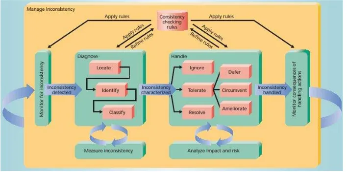
Inconsistency means any situation in which a set of description does not obey some relationship that hold between them. The relationship here can be expressed as a consistency rule against which description can be checked (Nuseibeh et al. 2000). As mentioned in (Nuseibeh 1996), “inconsistency occurs if and only if a (consistency) rule has been broken”. Requirements consistency can be determined by ensuring each requirement externally consistent with its documented sources such as higher-level goals and requirements, ensuring each requirement externally consistent with all other related requirements of the same type or at the same requirements specification. For example, two requirements should neither be contradictory nor describe the same concepts using different words and make sure the constituent parts of each requirement internally consistent. For example, all parts of a compound precondition or post condition must be consistent (Anon n.d.). Nuseibeh et al. (Easterbrook & Nuseibeh 1995; Nuseibeh et al. 2000; Nuseibeh 1996) came out with a frame work to manage inconsistency (see Figure 1.1), which provides a basis for inconsistency management activities. This framework explained how we can use consistency checking rules from the monitoring for inconsistency until monitoring the consequences of the handled inconsistency.
Figure 1.1: A framework for managing inconsistency
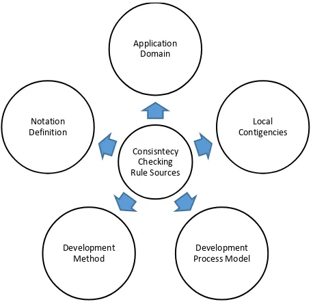
Nuseibeh et al. (2000) said, “Consistency rules provide an indication of possible inconsistencies in a description. Consistency checking rules can emerge from several sources such as (see Figure 1.2); Notation definitions; for example, in a strongly typed programming language, the notation requires that the use of each variable be consistent with its declaration. Development methods; for example, a method for designing distributed systems might require that for any pair of communicating subsystems, the data items to be communicated must be defined consistently in each subsystem interface. Development process models; a process model typically defines development steps, entry and exit conditions for those steps, and constraints on the products of each step. Local contingencies; sometimes a consistency relationship occurs between descriptions, even though the notation, method, or process model does not predetermine this relationship. For example, a particular timing constraint in requirement A must be the same as the timing constraint in requirement B. Application domains; many consistency rules arise from domain-specific constraints. For example, the telecommunication domain might impose constraints on the nature of a telephone call. Such constraints can be specified as consistency rules to be checked during development.”
Figure 1.2: Consistency checking rule sources
There are several techniques or approaches to validate the requirements such as requirements review, prototyping, model validation, requirements testing and etc. Different approaches and tools (Liang & Wu 2004; Hua-xiao et al. 2013; Kamalrudin 2009; Li 2011) have been proposed by the researchers in different ranging of inconsistency management, from diagnosing to handling the inconsistencies. Every researcher stated that how important it is to have good techniques to manage the inconsistencies in requirements regardless at any phase in software development it is being implemented.
In this research, we aim to justify the consistency checking rules for two commonly used UML models in software development which are, Activity diagram (AD) and Class diagram (CD) by using logical approach. The motivation for this research is because there is still lack of researches focusing on these two models, even though activity diagram is the one of the top five most used UML diagrams in industry and the fact that the number one most used UML diagram is Class diagram are the reasons why we chose to focus on these two models (Reggio et al. n.d.). The feedback we got from the questionnaire regarding the most
used UML diagrams, which the respondents chose activity diagram as their most used UML diagram in their development also has convinced us to focus on these models. Activity diagrams are usually associated to a class as such, they model the operations flow inside the class. Nevertheless, the activity diagram also allows a hierarchical decomposition, through the use of sub activity states, and so it can model several classes related by class aggregation. Through the use of external events we can even synchronize several activity diagrams. We then validated the rules by providing examples of models from a case study.
1.2 Problem Statements
The problem statements as described below:
1) Typical SRS written by using Natural Language (NL) is prone to misunderstanding because lack of clarity which is lead to requirement inconsistency.
2) Conflicting in UML models because of different notations/elements used from each other to describe the same functionality which is lead to inconsistency.
3) The constant changes of requirements due to changing circumstances that leads to requirement specification inconsistency.
1.3 Research Questions
The study will examine key research questions (RQ) as described below:
1) What are the most UML diagrams used by the industrial experts in software development field?
2) What are the existing rules proposed by the researchers to check the inconsistency between Activity diagram (AD) and Class diagram (CD)?
3) What are the suitable parameters that can be used as rules for checking the consistency of requirements between Activity diagram (AD) and Class diagram (CD)?
1.4 Research Objectives
Through this research, we aim to justify the existing consistency rules that can check the consistency between the Activity diagram (AD) and Class diagram (CD) by using logical approach.
This project embarks on the following objectives:
1) To explore the existing consistency rules between activity and class diagram.
2) To justify the existing rules between activity and class diagrams using logical approach.
3) To evaluate the rules justification by using a case study.
1.5 Research Scopes
The scope for this research is focusing on proposing justification for consistency checking rules between Activity diagram (AD) and Class diagram (CD). These two models
(AD and CD) are the most used UML models in software development field (Reggio et al. n.d.). The analysis from the literature review will be used to propose the rules. Since this research involved with the industry, official approval from the selected software house was obtained to have the information and documents gathered for the sole use of analysis and knowledge discovery purposes.
1.6 Significant and Research Contribution
This research will significantly help others to get a better understanding why requirements consistency validation is important in software development industry, especially for checking the consistency between requirements models. This study should be able to encourage other researchers to do more research on consistency rules for these two models. The contribution of this research is the justification of consistency rules between Activity diagram (AD) and Class diagram (CD) using logical approach.
1.7 Summary
This chapter briefly described about the problems and impact of the inconsistency in requirements specification to the software development. The chapter also covered about the research questions that have been considered for the study and the objectives of the research. Research scopes are explained as well as the significant and the contribution of the research.
CHAPTER 2
LITERATURE REVIEW
2.1 Introduction
This literature review focused on studies, review, and examines the requirements validation techniques and models consistency checking. The section starts with reviewing the existing requirements validation techniques and briefly describing the models consistency checking. The next section will review the models consistency checking approaches and rules that have been proposed by other researchers and lastly, the last section will review the rules which are going to be used in this study.
2.2 Requirements Validation Techniques
Kotonya and Sommervile (1998) stated in their book, there are several techniques or methods to validate the requirements such as requirements review, prototyping, requirements testing and model validation. Even though requirements review is a very effective way of discovering problems, it does involve a lot of time and expense in order to conduct the meeting, gather all the stakeholders and hire experts to form a multidisciplinary team for reviewing. Prototyping is a good method to demonstrate the requirements to the multiple stakeholders and end-users as in they may find it easier to understand and discover the problems and what need to be improvised. However, this only can be done if the prototype has
been developed during requirements elicitation because it is very not cost effective to develop a prototype just for the validation. Requirements testing can be done by using test cases for the requirements to reveal the problems. But this requirements testing which involves a lot of test cases takes quite a lot of time to execute which is delayed the development phase. Acharya and George (2005) used a combination of techniques, like specification inspection and testing the executable specification of a prototype using test cases, to validate the specification against the requirements as well as to ensure that the specified consistency conditions are respected and maintained by the operations defined in the specification. Model validation such as UML models (Object diagram (OD), Collaboration diagram (COD), Sequence diagram (SD) and etc.) could be checked to see whether the models are self-consistent or not.
2.3 UML Models Consistency Checking
The UML models able to illustrate both static and behavior abstractions. The static structure of a software basically is represented by using a class diagram, and, a behavior of the software is represented using behavioral models such as activity diagram, state chart diagram or sequence diagram. A class diagram is a compilation of classes and their associations. A class in a class diagram can describe the attributes and operations, but the actual behavior of these operations is represented by using behavioral models. The UML behavioral models are used to describe behavior of an object of a class during its lifetime. These models are comprised of states and transitions, where each transition is annotated with an operation. The operation on the transition depicts what happens to the object during its whole lifetime (Khan 2013). Among the behavioral models, the activity diagram is mostly not given much consideration by the researchers. This is quite unfair as the activity diagram is actually very