UNIVERSITI TEKNIKAL MALAYSIA MELAKA
Tool Wear Characterization of Carbide Cutting Tool
Insert in a Single Point Turning Operation of AISI D2
Steel
Report submitted to Universiti Teknikal Malaysia Melaka in partial fulfillment for Bachelor of Manufacturing Engineering
(Manufacturing Process)
By
Mohammad Syafiq bin Halim
B 050410038
Faculty of Manufacturing Engineering Universiti Teknikal Malaysia Melaka
UTeM Library (Pind.1/2007)
UNIVERSITI TEKNIKAL MALAYSIA MELAKA
BORANG PENGESAHAN STATUS LAPORAN PSM
JUDUL:
Tool Wear Characterization of Carbide Cutting Tool Inserts in a Single Point Turning Operation of AISI D2 steel
SESI PENGAJIAN: Semester 2 2007/2008
Saya MOHAMMAD SYAFIQ BIN HALIM
mengaku membenarkan laporan PSM / tesis (Sarjana/Doktor Falsafah) ini disimpan di Perpustakaan Universiti Teknikal Malaysia Melaka (UTeM) dengan syarat-syarat kegunaan seperti berikut:
1. Laporan PSM / tesis adalah hak milik Universiti Teknikal Malaysia Melaka dan penulis.
2. Perpustakaan Universiti Teknikal Malaysia Melaka dibenarkan membuat salinan untuk tujuan pengajian sahaja dengan izin penulis.
3. Perpustakaan dibenarkan membuat salinan laporan PSM / tesis ini sebagai bahan pertukaran antara institusi pengajian tinggi.
4. *Sila tandakan (√) SULIT
TERHAD
TIDAK TERHAD
(Mengandungi maklumat yang berdarjah keselamatan atau kepentingan Malaysia yang termaktub di dalam AKTA RAHSIA RASMI 1972)
(Mengandungi maklumat TERHAD yang telah ditentukan oleh organisasi/badan di mana penyelidikan dijalankan)
FAKULTI KEJURUTERAAN PEMBUATAN
Rujukan Kami (Our Ref) : 11 Januari 2012
Rujukan Tuan (Your Ref):
Pustakawan
Perpustakaan Universiti Teknikal Malaysia Melaka (UTeM) Taman Tasik Utama, Hang Tuah Jaya,
Ayer Keroh, 75450, Melaka
Saudara,
PENGKELASAN LAPORAN PSM SEBAGAI SULIT/TERHAD
- LAPORAN PSM SARJANA MUDA KEJURUTERAAN PEMBUATAN (PROCESS): MOHAMMAD SYAFIQ BIN HALIM
TAJUK: Tool Wear Characterization of Carbide Cutting Tool Inserts in a Single Point Turning Operation of AISI D2 steel
Sukacita dimaklumkan bahawa tesis yang tersebut di atas bertajuk “ Tool Wear Characterization of Carbide Cutting Tool Inserts in a Single Point Turning Operation of AISI D2 steel ” mohon dikelaskan sebagai terhad untuk tempoh lima (5) tahun dari tarikh surat ini memandangkan ia mempunyai nilai dan potensi untuk dikomersialkan di masa hadapan.
Sekian dimaklumkan. Terima kasih.
“BERKHIDMAT UNTUK NEGARA KERANA ALLAH”
Yang benar,
………..
Prof. Dr. Mohd. Razali bin Muhamad
Dekan,
Fakulti Kejuruteraan Pembuatan
UNIVERSITI TEKNIKAL MALAYSIA MELAKA
Karung Berkunci 1200, Ayer Keroh, 75450 Melaka
DECLARATION
I hereby declare that this report entitled “Tool Wear Characterization of Carbide
Cutting Tool Inserts in a Single Point Turning Operation of AISI D2 steel” is the
result of my own research except as cited in the references.
Signature : ………
Author’s Name : Mohammad Syafiq bin Halim
APPROVAL
This report is submitted to the Faculty of Manufacturing Engineering of UTeM as a partial fulfillment of the requirements for the degree of Bachelor of Manufacturing
Engineering (Process). The members of the supervisory committee are as follow:
Prof. Dr. Mohd. Razali bin Muhamad
(PSM Supervisor)
i
ABSTRACT
ii
ABSTRAK
iii
DEDICATION
iv
ACKNOWLEDGEMENTS
v
List Of Abbreviations, Symbols, Specialized Nomenclature……… xi
vi
2.6 Surface Roughness……….. 14
2.6.1 Symbols for Surface Roughness………... 15
2.6.2 Measuring surface Roughness………... 16
2.7 Machining Parameters, Tool Wear and surface Roughness Interaction…. 17 2.8 Design of experiment (DOE)……….. 18
4. RESULTS AND DISCUSSIONS……….. 27
4.1 Overview………. 27
4.4.4 Interaction Factor Affected Volume Removed/Flank Wear Ratio…… 45
4.5 Output Response Optimization……….. 48
vii
4.5.2 Optimization on Volume Removed/Flank Wear Ratio………. 51
4.5.3 Optimization on Both Output Response……… 53
5. CONCLUSION………. 55
REFERENCES……….. 56
APPENDICES
viii
2.6(c) Coordinates Used for Surface Roughness 16
2.7 Standard Lay Symbols for Engineering Surfaces 17
2.8a Measuring With Stylus 18
2.8b Path of The Stylus 18
3.1 Methodology Flow Chart 22
4.1 Depth of cut for surface roughness 31
4.2 Cutting speed for surface roughness 32
4.3 Feed rate for surface roughness 33
4.4 Cutting speed and depth of cut interaction 35
4.5 Cutting speed and feed rate interaction 36
4.6 Depth of cut and feed rate interaction 37
4.7 Cutting speed for volume removed/flank wear ratio 40
4.8 Feed rate for volume removed/flank wear ratio 41
4.9 Depth of cut for volume removed/flank wear ratio 42 4.10 Interaction between depth of cut and feed rate on volume
removed/flank wear ratio
43
4.11 Interaction of cutting speed and depth of cut on volume removed/flank wear ratio
44
4.12 Interaction of cutting speed and feed rate on volume removed/flank wear ratio.
45
4.13 3D optimization graph of surface roughness 47
ix
x
LIST OF TABLES
2.1 AISI D2 Steel Composition 14
3.1 Material Specifications 23
3.2 Work Material Composition 24
3.3 Experiment Matrix 25
3.4 Measuring Equipments Specifications 26
4.1 Experimental results 28
4.2 Fit Summary (sequential model sum of squares) for response surface quadratic model
29
4.3 Fit Summary (Lack of Fit Tests) 29
4.4 ANOVA Table for response surface quadratic model (partial sum of squares)
30
4.5 Fit Summary (sequential model sum of squares) for response volume removed/flank wear ratio
39
4.6 Fit Summary (Lack of Fit Tests) 39
4.7 ANOVA Table for volume removed/tool wear quadratic model (partial sum of squares)
40
4.8 Optimum setting for minimum surface roughness 50
xi
ISO - International Organization for Standardization
Mn - Manganese
Mo - Molybdenum
NIST - National Institute of Standards and Technology RSM - Response Surface Methodology
TiC - Titanium Carbide
V - Vanadium
1
CHAPTER 1
INTRODUCTION
1.1 Background of project
Cutting tool commonly used in metalworking for roughing, drilling, semi finishing and finishing applications and they are also used in making metal objects and metal parts. There are many types of cutting tool that come in hundred of shapes, sizes and uses. Some of the most commonly used cutting tools are angle cutters, end mills, grinding wheels and turning tools.
Wear phenomena has become a nightmare in machining industry because it is absolutely affecting the quality of the product and also the tool life. There are two main types of wear in a cutting tool, flank wear and crater wear. Cutting tool plays an important role in producing good quality of products. Careful selection of cutting tool for machining process for its specific applications is imperetive; to minimize the tool failure during machining process. So, the purpose of this study is to characterize the tool wear of carbide cutting tool insert in single point turning operation of AISI D2 steel.
According to Kalpakjian and Schmid (2001), cutting fluid account up to 15
percent of a shop’s production costs. Cutting fluid especially that containing oil has
2
proposed regulations is rapidly raising the price of cutting fluid hence many machine shops considering eliminating the costs by using dry cutting. Dry cutting is a machining process that uses no coolant during cutting process. Insert tools will perform better when the cutting temperature become higher because there is no coolant during cutting product quality. Basically, process parameter related with tool wear characteristic where different parameter will result in different degree of tool wear. From this, optimum parameter can be obtained that will produce minimum tool wear. This situation will produce better tool life performance thus producing good quality products efficiently.
1.3 Objectives
The main objectives of this research are:
1. To study influence of machining parameters such as cutting speed, feed rate and depth of cut to the tool wear of carbide insert.
3
3. To define the optimum machining parameter setting (cutting speed, feed rate and depth of cut) to minimize tool wear and surface roughness using RSM for single point turning carbide cutting tool insert on AISI D2 steel work material.
1.4 Scope
To ensure the objective is obtained, the study will be focused on:
1. Tool wear characterization of carbide cutting tool insert.
2. The tool wear to be analyzed are flank wear and crater wear.
3. The experiment will be done using dry cutting single point turning operation.
4. Machining parameters to be used are feed rate, cutting speed and depth of cut.
5. Work material which is AISI D2 steel.
4
CHAPTER 2
LITERATURE REVIEW
2.1 Introduction
This chapter covers the published work of researchers in the field of machining and cutting tools. In specific, it covers the study on the interaction between cutting parameters and resultant tool wear and surface roughness. Also included in this chapter are machining processes, cutting tool, tool wear, work material, surface roughness, influence of machining parameters to the tool wear and surface roughness followed by design of experiment.
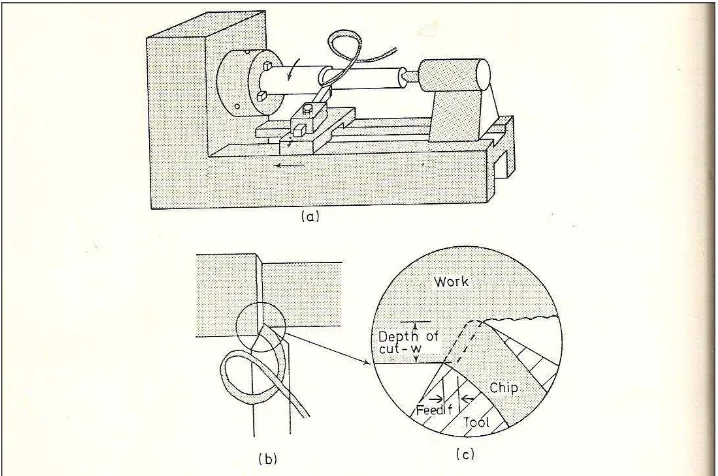
2.2 Turning Process
5
Figure 2.1 Turning process
Figure 2.1 (c) shows the feed rate (f), which is the distance moved by the tool in axial direction at each revolution of the work while Figure 2.1 (b) and (c) shows the depth of cut (w), which is the thickness of metal removed from the bar and measured in a radial direction. The cutting speed (V) means the rate at which the uncut surface of the work passes the cutting edge of the tool. The combination of these three gives the rate of metal removal. Basically, cutting speed and feed rate are adjusted to get optimum cutting conditions while depth of cut is fixed by the initial size of working material and products size.
2.2.1 Machining Parameters
6
(2007) shows that better tool life is obtained in lowest feed rate and lowest cutting speed combination. This study consists of three machining parameters which are cutting speed, feed rate, and depth of cut.
2.3 Cutting Tool
In general, cutting tool can be defined as part of a machine tool which removes material from the work piece by the used of a cutting medium. In industrial field, many types of cutting tool are used for machining process. Based on Schneider (2001), cutting tool need to have the certain characteristics:
1. Hardness: Hardness and strength of the cutting tool must be maintained at elevated temperatures also called hot hardness.
2. Toughness: Toughness of cutting tool is needed so that tools do not chip or fracture, especially during interrupted cutting operations.
3. Wear Resistance: Wear resistance means the attainment of acceptable tool life before tools need to be replaced.
Insert is one of the cutting tools that are widely used in machining process and it will be used as the cutting tool for this study. Brief explanation about insert will be featured in the next sub-topic.
2.3.1 Cutting Tool Insert
7
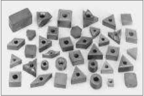
fresh cutting edge. This will effectively increase the life of the tool insert. Figure 2.2 shows some various shapes of insert.
Figure 2.2 Shapes of insert
2.3.2 Cutting Tool Insert Material
8 2.4 Tool Wear
Tool wear normally exist during machining process. In general, tool wear is a gradually process like the wear of the tip of an ordinary pencil. The rate of tool wear depends on tool and work piece materials, tool shape, process parameters and the machine tool itself (Kalpakjian and Schmid, 2001). Basically, tool wear will increase cutting force and cutting temperature and also produce poor surface finish. There are various types of tool wear such as flank wear, crater wear, and build up edge, glazing and edge wear. This study will be focusing on flank wear and crater wear.
2.4.1 Flank Wear