MODELING AND SIMULATION OF ENGINE MANAGEMENT SYSTEM
SHAHRUL HAFEZ BIN MOHD RAZALI
The PSM (Projek Sarjana Muda) report is considered as one of the essential for students to complete their bachelor program in Mechanical Engineering
(Automotive)
Faculty of Mechanical
Universiti Teknikal Malaysia Melaka
I/We admit that have read this work and in my opinion this work is enough in terms of scope and quality to bestowal Bachelor of Mechanical Engineering (Automotive)
Signature : ………
Supervisor’s Name : ..………..
ii
“Saya akui laporan ini adalah hasil kerja saya sendiri kecuali ringkasan dan petikan yang tiap-tiap satunya saya telah jelaskan sumbernya”
iii
DEDICATION
To my beloved mother, father, brother and sister, and all my friends All member of Bachelor of Mechanical Design Innovation Engineering (BMCA)
All lecturers from BMCA department Staff of Faculty Mechanical Engineering
Staff of Universiti Teknikal Malaysia Melaka (UTEM)
Do You Have Time To Pray?
iv
ACKNOWLEDGEMENT
Syukur alhamdulillah. Thanks to Allah (swt) because his bless giving me the strength to complete my PSM project. First of all, I would like to extend my gratitude to my supervisor, Mr. Herdy Rusnandi for their time and help. Thank you for guiding me through out this period.
I also like to take this opportunity to say thank you to my entire friend that always help me. Then I would like to show my gratitude to both of my parent and siblings that always support me and pray for me. Because of them, I have gain more strength to face my obstacle. Last but not least, thank to all that I not mention specificly for help me to finish this report.
v
ABSTRACT
vi
ABSTRAK
vii
TABLE OF CONTENT
NO. TITLE PAGE
PENGAKUAN ii
DEDICATION iii
ACKNOWLEDGEMENT iv
ABSTRAK v
ABSTRACT vi
TABLE OF CONTENT vii
LIST OF FIGURE ix
LIST OF SYMBOL x
LIST OF APPENDIX xi
CHAPTER 1 INTRODUCTION
1.0 Introduction 1
1.1 Objective 1
1.2 Scope 1
1.3 Problem statement 2
CHAPTER 2 LITERATURE REVIEW
2.0 EMS literature review 3
2.1 What is EMS? 3
2.2 Injection system 7
2.3 Ignition system 16
2.4 Idle speed control 24
2.5 Diagnostic system 25
CHAPTER 3 METHODOLOGY
3.0 Engine management system methodology 28
3.1 Engine platform selection 30
3.2 Review electronic fuel injection system 30
3.3 Software selection 31
3.4 Equation use in injection system 34
3.5 Simulation process 35
viii
CHAPTER 4 RESULT AND DISCUSSION
4.0 Simulation result and discussion 40
4.1 Fuel quantity percent in idle speed 40
4.2 Fuel quantity percent in partial throttle 42
4.3 Fuel quantity percent in full throttle 43
CHAPTER 5 CONCLUSSION AND RECOMENDATION
5.0 Conclusion 44
5.1 Conclusion of project 44
5.2 Recommendation and further work 45
ix
LIST OF FIGURE
NO TITLE PAGE
2.1 EMS diagram 5
2.2 Injection system 8
2.3 Single point injection 11
2.4 Multipoint injection 13
2.5 Basic component on injection system 14
2.6 Ignition management with distributor trigger 15 2.7 Ignition management with distributorless trigger 16 2.8 Ignition Management distributorless wasted spark 16 2.9 ignition management distributorless with cam sensor 22
2.10 Ignition basic system 24
2.11 Idle speed control system 26
3.1 Research Methodology flow chart 27
3.2 MATLAB software 29
3.3 SIMULINK library browser 33
3.4 Electronic fuel injection system control block diagram 34
3.5 Idle speed block diagram 39
3.6 Part throttle block diagram 40
3.7 Full throttle block diagram 41
3.8 Cut off block diagram 41
4.1 Fuel quantity percent for idle speed 41
4.2 Fuel quantity percent in part throttle 42
x
LIST OF SYMBOLS
SYMBOL DEFINATION
D displacement of engine (litres) Rpm revolution per minute
Ve volumetric efficiency
EGR exhaust gas recirculation (litre/s) da air density
i
p intake air pressure
i
t intake air temperature
o
d value relates density under sea level standard day (SLSD)
o
p value relates pressure under SLSD
o
t value relates temperature under SLSD AFR desired air-fuel ratio
xi
LIST OF APPENDIX
APPENDIX TITLE PAGE
1
CHAPTER 1
INTRODUCTION
1.0 Introduction
This chapter is about the introduction of the project. There are including project objective, scope and project problem statement.
1.1 Objective
The main objective of this project is to develop modeling and simulation of engine management system for teaching and learning process.
1.2 Scope
2 1.3 Problem statement
3
CHAPTER 2
LITERATURE REVIEW
2.0 EMS literature review
Before we doing something, we must know what we want doing. Because of that question, in this chapter, overview about the engine management system will be explained.
2.1 What is EMS?
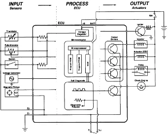
The performance and emissions that today's engines deliver would be impossible without the electronics that manage everything from ignition and fuel delivery to every aspect of emissions control. Electronics make possible engines that deliver excellent performance, good fuel economy and produce almost no pollution. Many Engine management systems or EMS today have 16-bit and even 32-bit processors. Though not as powerful as the latest desktop personal computers, EMS can still crunch a lot of information.
4
Figure 2.1 EMS diagram (source: www.autoshop101.com)
2.1.1 The sensors
The oxygen sensor provides information about the fuel mixture. The EMS uses this to constantly re-adjust and fine tune the air/fuel ratio. This keeps emissions and fuel consumption to a minimum. A bad oxygen sensor will typically make an engine run rich, use more fuel and pollute. Oxygen sensors deteriorate with age and may be contaminated if the engine burns oil or develops a coolant leak. On 1996 and newer vehicles, there is also an additional oxygen sensor behind the catalytic converter to monitor converter efficiency.
5 Once the engine reaches a certain temperature, the EMS starts using the signal from the oxygen sensor to vary the fuel mixture. This is called "closed loop" operation, and it is necessary to keep emissions to a minimum.
The throttle position sensor (TPS) keeps the EMS informed about throttle position. The EMS uses this input to change spark timing and the fuel mixture as engine load changes. A problem here can cause a flat spot during acceleration (like a bad accelerator pump in a carburetor) as well as other drivability complaints.
The Airflow Sensor, of which there are several types, tells the EMS how much air the engine is drawing in as it runs. The EMS uses this to further vary the fuel mixture as needed. There are several types of airflow sensors including hot wire mass airflow sensors and the older flap-style vane airflow sensors.
Some engines do not have an airflow sensor and only estimate how much air the engine is actually taking in by monitoring engine rpm and using inputs from the throttle position sensor, a manifold absolute pressure sensor (MAP) and manifold air temperature (MAT) sensor. Problems with the airflow sensor can upset the fuel mixture and various drivability problems such as hard starting, hesitation, stalling, and rough idle, etc.
The crankshaft position sensor serves the same function as the pickup assembly in an engine with a distributor. It does two things: It monitors engine rpm and helps the computer determine relative position of the crankshaft so the EMS can control spark timing and fuel delivery in the proper sequence.
6 vacuum, which the EMS also uses to determine engine load. The MAP sensor's input affects ignition timing primarily, but also fuel delivery.
Knock sensors are used to detect vibrations produced by detonation. When the EMS receives a signal from the knock sensor, it momentarily retards timing while the engine is under load to protect the engine against spark knock.
The EGR position sensor tells the EMS when the exhaust gas recirculation (EGR) valve opens and how much. This allows the EMS to detect problems with the EGR system that would increase pollution.
The vehicle speed sensor (VSS) keeps the EMS informed about how fast the vehicle is traveling. This is needed to control other functions such as torque converter lockup. The VSS signal is also used by other control modules, including the antilock brake system (ABS).
2.1.2 Name of Control Unit in EMS
ECU- engine or electronic control unit
PCM- power train control module
DCM- digital motor electronic
7 2.2 Injection system
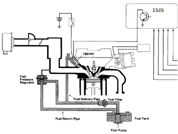
[image:19.612.180.535.221.489.2]Injection system is the main system of a car. Nowadays, most of the modern car has injection system. For the engine that has fuel injection, EMS will determine the amount of fuel to provide based on number of parameter. Figure below show the injection system diagrammed.
Figure 2.2 Electronic fuel injection system (source: www.autoshop101.com)
Component parts
Fuel tank Holds a reservoir of fuel for the engine, is normally baffled to prevent fuel sloshing around and the resultant fuel starvation.
Fuel filter Since an injector pump is a positive displacement pump any foreign material ingested can stall the pump and kill it stone dead; this pre-filter prevents rubbish from entering the pump.
8 and 4 bar (43 and 58PSI). On some installations the pump is housed inside the fuel tank with rudimentary filtration, the fuel filter then follows in the fuel line. Fuel line Fuel pipe that transports the fuel from the pump to the fuel rail. Fuel rail A small fuel gallery from which the injectors take their fuel
supply.
Injectors Electric valves which when open allow fuel to be injected into the engine under high pressure.
Pressure regulator A device that keeps the fuel pressure at a constant rate and
returns any excess fuel to the tank
Fuel return line Fuel pipe which bleeds excess fuel back to the fuel tank
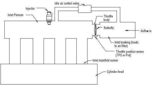
2.2.1 Single point injection
Single point injection systems use a single fuel injector that injects into the inlet manifold. The fuel injected is drawn in to the cylinders by airflow in a similar way to a carburettor. Because of the variations in length and orientation of the various branches in the inlet manifold, the fuel distribution characteristics are not ideal so economy or emissions and throttle response suffer as a result.
[image:20.612.153.456.503.671.2]9
Although the injector position is shown in the centre of the intake manifold, this is just for clarity, usually the injector will be mounted on or near the throttle body where air velocity is at its highest.
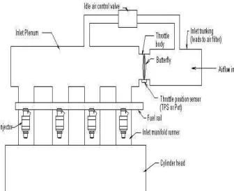
2.2.2 Multi point injection
Multi point injection systems are much more common and generally have an injector per cylinder located in each individual manifold runner. This configuration gives much better control of fuelling and better emissions since the fuel can be metered more closely, and there is less opportunity for the fuel spray to condense or drop out of the airflow since it is introduced as four small streams rather than one large one. The closer to the inlet valve the fuel injection takes place, the better the economy and transient throttle. Most systems use one injector per cylinder but on certain engines have only two inlet ports since two cylinders share a Siamese port, in this case multi-point would mean two injectors, one per inlet port, this is still better than a single injector system.
With multi-point (or multi injector) systems there is scope for timing the injection of fuel to better suit the engines duty cycle. If the EMS knows the relative position of each cylinder within the engines cycle (usually from a cam phase sensor) then it can fire the injectors at the optimum time for that cylinder. This is known as sequential injection; sometimes the EMS will only have knowledge of the crank position rather than the duty cycle position, in this case it can optimise for a pair of cylinders, this is known as semi-sequential or grouped injection.
10
Figure 2.4 Multipoint injection (source: www.engine LogicsInc.)
2.2.3 Components of a fuel injection system
To supply right amount of fuel at the right injector timing, EMS must know some value from such parameter.
2.2.3.1 Crank sensor
11 exactly the crank position as well as speed. Although the EMS knows the engines crank position from this sensor, it does not know the engines cycle position.
2.2.3.2 Hall effect switches
A Hall Effect switch is frequently used to sense engine speed and crankshaft position. It provide a signal each time a piston reach top dead centre, and the signal serves as the primary input on which ignition timing is calculated. This type of sensor is commonly use nowadays because it provides a digital signal. On some applications, a separate Hall Effect switch is used to monitor camshaft position as well.
2.2.3.3 Throttle Position Sensor.
The most common engine load sensor especially on after market systems. A TPS is a small potentiometer (or ‘throttle pot’) which is connected directly to the throttle shaft and turns with it. It returns a value to the EMS depending on the throttle position. TPS sensors are normally used on performance engines where airflow sensors might become confused because of pulses in the inlet tract, because they do not measure airflow but simply give a throttle position, airflow is assumed to be constant for any given engine speed and throttle position. If the engine is further modified the airflow characteristics may change and the engine may need re-mapping. EMS systems that use direct airflow measurement can often cope with changes more effectively and can alter the fuelling to suit without a re-mapping session.
2.2.3.4 Mass air flow sensor or Air metering flap
12 2.2.3.5 Manifold Air Pressure sensor.
These measure the vacuum or air pressure in the inlet manifold that in turn gives an indication of load, more commonly used on turbocharged engines to give an indication of boost level.
2.2.3.6 Hot wire
This approach uses a heated platinum wire and measures the current required to keep it at a particular temperature. As air passes over the wire it cools it down, the more air that passes, the greater the cooling effect and therefore the greater the current. The hot wire system can be also be confused by reverse pulses when more extreme cams are used.
2.2.3.7 Engine temperature