UNIVERSITI TEKNIKAL MALAYSIA MELAKA
IMPROVEMENT OF DRILL GEOMETRY FOR DRILLING
CFRP COMPOSITE
This report submitted in accordance with requirement of the Universiti Teknikal
Malaysia Melaka (UTeM) for the Bachelor Degree of Manufacturing Engineering
(Manufacturing Process) (Hons.)
By
SYAHIBUL HAFIZ BIN BASIR
B051010240
891015-04-5589
FACULTY OF MANUFACTURING ENGINEERING
UNIVERSITI TEKNIKAL MALAYSIA MELAKA
BORANG PENGESAHAN STATUS LAPORAN PROJEK SARJANA MUDA
TAJUK: IMPROVEMENT OF DRILL GEOMETRY FOR DRILLING CFRP
COMPOSITE.
SESI PENGAJIAN: 2013/14 Semester 2
Saya SYAHIBUL HAFIZ BIN BASIR
mengaku membenarkan Laporan PSM ini disimpan di Perpustakaan Universiti Teknikal Malaysia Melaka (UTeM) dengan syarat-syarat kegunaan seperti berikut:
1. Laporan PSM adalah hak milik Universiti Teknikal Malaysia Melaka dan penulis. 2. Perpustakaan Universiti Teknikal Malaysia Melaka dibenarkan membuat salinan
untuk tujuan pengajian sahaja dengan izin penulis.
3. Perpustakaan dibenarkan membuat salinan laporan PSM ini sebagai bahan pertukaran antara institusi pengajian tinggi.
DECLARATION
I declare that this report entitle “Improvement Of Drill Geometry For Drilling Cfrp
Composite” is the result of my own research except as cited in the references.
Signature: ………
Name: Syahibul Hafiz Bin Basir
APPROVAL
This report is submitted to the Faculty of Manufacturing Engineering of Universiti
Teknikal Malaysia Melaka (UTeM) as a partial fulfillment of the requirements for
the degree of Bachelor of Manufacturing Engineering (Manufacturing Process)
(Hons.). The member of the supervisory committee is as follow.
……… (Supervisor)
i
ABSTRAK
Secara amnya, CFRP disertai dan berkaitan dengan menyertai elemen ke dalam satu
bahagian komposit. Penggerudian CFRP boleh merosakkan lubang dalam bentuk
nyahikatan, serat tarik keluar, permukaan kasar, kerepek tepi, serat yg belum
ditebang dan penggunaan alat pesat yang bersekutu dengan gerudi ciri-ciri geometri.
Dari sastera, ia menunjukkan bahawa latihan menggunakan mata gerudi dengan reka
bentuk yang sesuai adalah jenis gerudi yang paling sesuai untuk penggerudian CFRP.
Oleh itu, projek ini bertujuan untuk menyelidik dan mencadangkan reka bentuk
optimum mata gerudi untuk mengesan penggerudian CFRP komposit. Dua pisau
menggerudi rekabentuk geometri akan disiasat iaitu sudut mata dan alat aspek
kepada kekasaran permukaan lubang, nyahkaitan dan daya penggerudian
menggunakan statistikal RSM. Sejumlah jenis gerudi-reka dengan sudut yang
berbeza-beza mata dan alat abih. Dari siasatan yang dijalankan, ia menunjukkan
bahawa penggerudian gentian komposit bertetulang CFRP polimer terjejas dengan
ketara permukaan ke arah pembentukan serat, duri dan menyebabkan keadaan
kekasaran permukaan. Penjelasan mengenai evolusi daya pemotongan dan analisis
perkembangan kerosakan telah membantu dalam memahami fenomena penggerudian
dengan meningkatkan sudut titik dan abih. Nilai bilangan nyahkaitan terhasil
mengikut jenis yang berbeza dari mata alat gerudi direkabentuk yang menunjukkan
keadaan yang wujud pada permukaan bahan kerja penggerudian. Di samping itu,
reka bentuk geometri yang optimum untuk penggerudian CFRP adalah dengan
menggunakan 110 º titik sudut dengan lima alat abih. Satu set ujian eksperimen telah
dilakukan untuk mengesahkan reka bentuk alat optimum yang dipilih. Perjanjian
yang kukuh sebanyak 90% telah didapati antara meramalkan dan nilai sebenar
mengesahkan keberkesanan reka bentuk untuk penggerudian berkesan CFRP
ii
ABSTRACT
Generally, CFRP are joined and connected by joining elements into one composite
section. For this purpose, it is necessary to drill numerous holes which poses several
challenges due to its inhomogeneous materials that consist of fibre and matrix.
Drilling of CFRP can damage the hole in the form of delamination, fibre pull out,
rough surface, edge chipping, uncut fibre and rapid tool wear which associate with
the drill geometrical features. From literature, it shows that dagger drill with suitable
design is the most suitable drill type for drilling CFRP. Thus, this project attempts to
investigate and propose the optimal design of dagger drill for effectively drilling
CFRP composite. Two dagger drill geometric design will be investigate namely
point angle and tool facet on hole surface roughness, delamination and drilling force
using statistical RSM. Total of nine drill design are fabricate with varying point
angle and tool facet. From the conducted investigation, it shows that drilling carbon
fiber reinforce polymer CFRP was substantially affected the surface towards fibre
formation, burr and lead to condition of surface roughness. The explanations about
evolution of cutting force and analysis of damage progression have assisted in
understanding the drilling phenomenon by increase the point angle and facet. The
value of delamination number produces by different type of drill bit tool in the
design expert demonstrated the circumstances prevailing at the workpieces drilling
surface. In addition, the optimal geometric design for drilling CFRP are by using
110º point angle with five tool facet. A set of experimental test were done to validate
the selected optimal tool design. The strong agreement of 90% were found between
predicted and actual value confirmed the effectiveness of the design for effective
iii
DEDICATION
I would like to dedicate this whole PSM report to my beloved family and beloved
siblings.
To my late mother ALLAHyarhammah Hjh. Zaharah Bt. Hj. Othman
iv
ACKNOWLEDGEMENT
“In the name of Allah, the most gracious, the most compassionate”
Alhamdullillah, thanks to Allah S.W.T., finally after facing a lot of challenges during
my final year project, lastly it is done. There are numbers of people have contributed
in different ways in completing this study with lots of support, indeed, this final year
project could not have been completed without any of you.
First of all, billion of thanks dedicated to my supervisor, Dr Raja Izamshah Bin Raja
Abdullah for his briefing and passionate guidance throughout the whole process of
completing this project as well as for teaching me the proper techniques of writing
reports. Thank you so much for all the guidance in helping me doing the project,
willing to answer the question that thrown to him and spending his time showing and
explaining to me about the equipment and machines that involve in certain process.
Last, I would like to express my appreciation to my family and my friend because a
v
CHAPTER 2: LITERATURE REVIEW (Composite and Drill) 6
2.1 CFRP composite 6
vi 2.6.1. Effect of tool parameter (material and geometry ) on delamination,
surface roughness 38
2.6.2. Effect of process on delamination, surface roughness 39
2.6.3. Effect of combination of tool and process parameter 39
2.7 Summary 40
3.4.2. Cutter design and fabrication using tool grinder 43
3.5 Drilling Parameter and Experimental Setup 56
3.5.1. Measurement devices. 57
4.2.3 Thrust force and Cutting Force (Dynamometer) 83
4.3 Optimization analysis 92
vii CHAPTER 5: CONCLUSION AND FUTURE WORK 97
5.1 Conclusion 97
5.2 Future work 98
REFERENCES 99 – 103
2.1 The Component Used on Airbus Series of Aircraft 12
2.2 Weight of Composite Used in Different Airbus 13
2.3 The Composite Component Used on Boeing Series Aircraft 14
2.4 Experimental Parameter for Drilling CFRP 28
2.5 Drill Bits with Various Shapes and Geometries 30
2.6 Parameter Condition 36
2.7 Parameter expectation for dagger drill 39
3.1 CFRP composite Aircraft 42
3.2 Tool Material properties Specification 43
3.3 Drill bit solid carbide after fabricate 55
4.1 The specification of experiment 62
4.2 Surface roughness result 63
4.3 Table ANOVA result for surface roughness 63
4.4 Optical Delamination result 66
4.5 Table ANOVA for delamination – inside 71
4.6 Table ANOVA for delamination – outside 79
4.7 Data Design expert 85
4.8 Table ANOVA result for cutting force 89
4.9 Table constraints experiment 92
4.10 Table solution for selected tool parameter 92
viii
1.1 Defect after drilling CFRP composite 3
2.1 Continuous Reinforcement Include Unidirectional,
Woven Cloth, and Helical Winding 7
2.2 Composite in Transport Aircraft TU-204 9
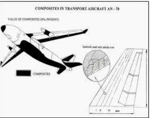
2.3 Value of Composite (Weight) 9
2.4 Boeing 787 Dreamliner Comercial Airplanes 50% Composite Structure 10
2.5 The Comparison Plot to Find Weight Saving with
Respect to Type of Aircraft 10
2.6 The Composite Material was Used in Fin Leading Edge and
Other Glass Fibre Fairing Panels. 11
2.7 Composite Used for Different Part of A-340 Aircraft 13
2.8 Composite Used for Different Part of B-777 Aircraft 15
2.9 Composite Materials Application on Airbus A320 16
2.10 Example of composite damage 17
2.11 Application of composite in airframe growing 18
2.12 Composite use since 1975 - 2010 18
2.13 Classification of Delamination 20
2.14 Drilling Induced Damage 20
2.15 Experimental setup for drilling of CFRP 22
2.16 a) twist drill, b) brad drill, c) dagger drill, d) step drill. 27
2.17 Other type of Drill Geometry (Brad and Spur Drill) 29
2.18 The Effect of Large Point Angle (top) and
Small Point Angle (bottom) On The Potential for
Creating Burrs at Drill Breakthrough 33
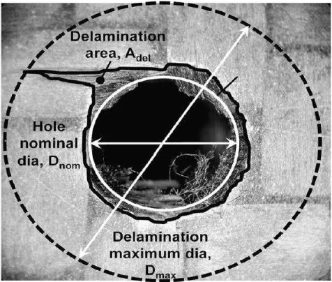
2.19 Quantification of Delamination 33
2.20 Trouble result after Making Hole 34
2.21 Others Result of Drilling CFRP 33
2.22 A poor Quality Hole 35
ix
2.23 A Good Quality Hole 35
2.24 Drills, Twist 120˚, Twist 85˚, Brad, Dagger, Step 37
2.25 Feed Rate Effect on Maximum Thrust Force 38
2.26 Last Ply Thrust Force Comparison 38
2.27 Feed Rate Influence On Hole Surface Roughness 39
2.28 Result Expectation CFRP Composite 40
3.1 Technical documentation of tool grinding machine 44
3.2 Side view of tool grinding machine 44
3.3 Front view of tool grinding machine 45
3.4 Operating elements of tool grinding machine 45
3.5 Adjusting index head to clamp tool 46
3.6 Tool that been fabricate by tool grinding machine 46
3.7 To synchronize the diamond cutter and tool diameter 47
3.8 Testing using diamond cutter 47
3.9 Plastic tool sample been test by using diamond cutter 48
3.10 Testing fabricate plastic tool diameter 10mm 48
3.11 Material solid carbide has been choosing as tool materials 49
3.12 Measuring and cut solid carbide using EDM Die Sinking. 49
3.13 Material solid carbide diameter 6mm 50
3.14 Enter tool diameter 6mm inside tool clamp 50
3.15 Clamping solid carbide tool 51
3.16 From index head adjusting angle of tool clamping at 5º 51
3.17 Vertical adjustment grinding head to move the cutter grinding 52
3.18 Using diamond cutter grinding 52
3.19 First facet of tool after grinding 53
3.20 First facet of tool with 5º angle grinding 53
3.21 Release clamp and rotate the tool for grinding second facet 54
3.22 The way to operate tool grinding machine 54
3.23 Flow chart of final year project 56
3.24 CNC drilling machine 3 – axis 57
x
3.26 Optical microstructure test 59
3.27 Quantification of delamination 59
3.28 Setup CFRP panel with dynamometer to measure cutting force 60
4.1 Normal plot of Residual surface roughness 64
4.2 Graph residual vs Predicted for surface roughness 64
4.3 Graph residual vs. run surface roughness 65
4.4 Model Graph 3D show for the point angle and facet surface roughness 65
4.5 Hole 1 delamination- in 0.70mm length 67
4.6 Hole 2 delamination – in 0.79mm length 67
4.27 Normal plot of Residual for delamination –out 80
xi 4.29 Residual vs. run for delamination – out 81
4.30 Model Graph 3D show for the point angle and facet delamination – out 81
4.31 Setup CFRP panel with Dynamometer 83
4.32 Cutting force measurement by using Dynamometer 84
4.33 Run 1, Tool 90º : 3 facet. 45.7764 N 85
4.34 Run 3, Tool 90º : 5 facet. 155.273 N 86
4.35 Run 4, Tool 100º : 3 facet. 188.995 N 86
4.36 Run 5, Tool 100º : 4 facet 227.173 N 87
4.37 Run 6, Tool 100º : 5 facet 194.244 N 87
4.38 Run 7, Tool 110º : 3 facet 212.738 N 88
4.39 Run 9, Tool 110º : 5 facet 199.768 N 88
4.40 Normal plot of Residual for cutting force 89
4.41 Residual vs. predicted for cutting force 90
4.42 Residual vs. run for cutting force 90
4.43 Model Graph 3D show for the point angle and facet for cutting force 91
4.44 Tool 9, 110º : 5 facet 93
4.45 Delamination – in hole 9. Average diameter 6.23mm 94
4.46 Delamination – out hole 9. Average diameter 5.935mm 95
1 This chapter provides the background of the research. The research will focus on the
improvement of new drill bit geometry for drilling CFRP composite with different fibre
orientation. The background of the research covers the development and current
achievement of drill geometry for drilling CFRP composite. Moreover, the problem
statements followed by the objectives and scope of the project are included.
1.1 Background
Carbon Fibre Reinforced Polymer (CFRP) have widely used in many of industries,
especially in aerospace industries due to the great in strength to weight ratio as well as
the ability to create large integrated structure.
The matrix for a CFRP composite is a plastic and the reinforcement is glass that has
been made into fine threads and often woven into a sort of cloth. The first modern
composite material was fibreglass. It is still widely used today for boat hulls, sports
equipment, building panels and many car bodies. On its own the glass is very strong but
brittle and it will break if bent sharply. The plastic matrix holds the glass fibres together
and also protects them from damage by sharing out the forces acting on them.
INTRODUCTION
2 Generally, CFRP composite are lighter and stronger than fibreglass but more expensive
to produce, some advanced composites are now made using carbon fibres instead of
glass. They are used in aircraft structures and expensive sports equipment such as golf
clubs.
More than 20% of the A380 is made of composite materials, mainly plastic reinforced
with carbon fibres. The new Airbus A380, the world‘s largest passenger airliner, makes
use of modern composites in its design. The design is the first large-scale use of
glass-fibre-reinforced aluminium, a new composite that is 25 % stronger than conventional
airframe aluminium but 20% lighter.
Generally, CFRP are joined and connected by joining elements into one composite
section. For this purpose, it is necessary to drill numerous holes which pose several
challenges due to its inhomogeneous materials that consist of fibre and matrix.
Drilling of CFRP can damage the hole in the form of delamination, fibre pull out, rough
surface, edge chipping, uncut fibre and rapid tool wear which associate with the drill
geometrical features. From literature, it shows that dagger drill with suitable design is
the most suitable drill type for drilling CFRP.
Thus, this project attempts to investigate and propose the optimal design of dagger drill
for effectively drilling CFRP composite. Two dagger drill geometric design will be
investigate namely point angle and tool facet on hole surface roughness, delamination
and drilling force.
1.2 Problem Statement
Drilling is one of the most important, frequently practiced and unavoidable machining
3 intricacy in structures necessitates creating holes to facilitate the process of assembly.
Composite materials pose additional difficulties while solving the problem of
controlling the drilling process. These difficulties arise from the anisotropic nature of
the material, as determined by the stacking sequence of the laminate. This prevents the
use of empirical models for control due to the difficulty in dealing with the large
number of parameters that determine the material characteristics, and of quantifying
them with any certainty.
There are several common problems associated with drilling carbon fibre composite
such as delamination, excessive tool wear, melting and softening of the matrix, fibre
pull-outs and scorching of the surface usually reported as the biggest concerns.
Delamination usually occurs when the last plies of the material do not withstand the
force exerted by the drill bit‘s chisel edge. In addition, the chip produced during drilling
of carbon fibre composites is in the form of abrasive dry dust. The ineffective extraction
of the chip is one of the major reasons for high tool wear rates. Tool wear is also related
to delamination, as the force necessary to cut the material increases with tool wear.
Figure 1 show the defects when drilling CFRP composite. Generally, the holes
performances are directly related with the drill geometry.
4 Therefore, a better understanding of the drilling of carbon composites with other shaped
of drill bits is necessary for further improvement and optimization leading to the quality
and productivity of the drilling process.
1.3 Aims and Objectives
1.3.1 Aims and Objectives
Based on the problem and difficulties on drilling CFRP composite, the aim and
objectives of this project are:-
a) To investigate the effects of dagger drill geometry design namely point
angle and tool facet on CFRP hole performances such as surface
roughness, delamination and drilling forces.
b) To propose on optimal dagger drill geometry design that can effectively
drilling CFRP composite.
c) To validate the effectiveness of the new propose drill geometry design.
1.4 Scopes
The scopes of this project are:-
a) Fabricate new dagger drill bit. Tool Parameter Point Angle: 90° - 110°. Facet:
3,4,&5.
b) Drilling CFRP and making hole process
c) Delamination and burr analysis.
5
1.5 Report structure
Generally, there are 5 chapters includes in this project. Chapter 1 represents the
introduction of the project. The contents included are background, problem statement,
objective, and scope and project background. The clear explanation regarding the
subtopics influence in this research covered in this chapter. Chapter 2 represents the
literature review on the background and basic information about project. Chapter 3
represents the methodology; this chapter included planning of the research and flow chart. This chapter included drawing product sketching and solid work, final design the
product to fabricate. Chapter 4 discuss on the detail and the implementation about
fabrication drill, by using Design Expert software to get parameter and drilling
experiment by using dynamometer method throughout the project. Chapter 5 will be
discussing the result and analyses obtain through the process and presentation of the
data that have been collected, the progression, experimental data and analysis stated in
this chapter and last will be the conclusion of the whole study and recommendation for
6 This chapter provides the definition of CFRP composite and a brief history of CFRP
composite technology for aircraft. In addition, the techniques and types of available drill
for CFRP drilling were also. Then, this chapter describes on the related work of drilling
CFRP composite. Finally, this chapter cover the damage and difficulties when drilling
CFRP composite.
2.1 CFRP composite
Composites CFRP are one of the most widely used materials because of their
adaptability to different situations and the relative ease of combination with other
materials to serve specific purposes and exhibit desirable properties.
The use of plastic resins has made possible the development of non-metallic materials
that are often superior to metals in strength or weight ratio, corrosion resistance, ease of
fabrication, and cost. Structural materials known as composites are made of many
different materials and in a variety of forms.
According to R.E. Horton and J.E. McCarty, 1987. (Damage Tolerance of Composites,
Engineered MaterialsHandbook, Vol 1). Continuous fibers have long aspect ratios,
while discontinuous fibers have short aspect ratios. Continuous-fiber composites
normally have a preferred orientation, while discontinuous fibers generally have a
LITERATURE REVIEW
7 random orientation. A fiber has a length that is much greater than its diameter. The
length-to-diameter (l/d) ratio is known as the aspect ratio and can vary greatly.
Figure2.1: Continuous reinforcements include unidirectional, woven cloth, and helical winding
Fibers produce high-strength composites because of their small diameter; they contain
far fewer defects (normally surface defects) compared to the material produced in bulk.
Continuous-fiber composites are often made into laminates by stacking single sheets of
continuous fibers in different orientations to obtain the desired strength and stiffness
properties with fiber volumes as high as 60 to 70 percent. As a general rule, the smaller
the diameter of the fiber, the higher its strength, but often the cost increases as the
diameter becomes smaller. Typical fibers include glass, aramid, and carbon, which may
be continuous or discontinuous. In addition, smaller-diameter high-strength fibers have
greater flexibility and are more amenable to fabrication processes such as weaving or
forming over radii. The advantages of composites CFRP are many, including lighter
weight, the ability to tailor the layup for optimum strength and stiffness, improved
fatigue life, corrosion resistance, and, with good design practice, reduced assembly
8
2.2. CFRP composite for Aircraft
According to Moorthy Chinnasamy, 2012. An important contribution to improve the
efficiency and performance can be achieved by decreasing the aircraft weight through
considerable usage of composite materials in primary aircraft structures. In the
competitive environment of aircraft industries it becomes absolutely necessary to
improve the efficiency, performance of the aircrafts to reduce the development and
operating costs considerably, in order to capitalize the market. A type of composite material called Carbon Fiber Reinforced Plastic (CFRP) is explored for the usage is
aircraft skin panels.
Currently, the use of composite materials has increased in various areas of science and
technology due to their special physical and mechanical properties. Composite materials
have attractive features, such as high ratios of strength-to-weight and
stiffness-to-weight, good corrosive resistance, and low thermal expansion. The high degree of
intricacy in composite structures necessitates special process to create holes in them for
the purpose of assembly. In surface transportation, reinforced plastics are the kind of
composites used because of their huge size. They provide ample scope and
receptiveness to design changes, materials and processes. The strength-weight ratio is
higher than other materials. Their stiffness and cost effectiveness offered, apart from
easy availability of raw materials, make them the obvious choice for applications in
surface transportation.
According to James R. Rardon, 1998. Newer aircraft use composite materials for many
structural parts, and the use of composite material for wingtips, cowling, fairing, flaps,
spoilers, and ailerons is common. Composite materials will be dividing into two
categories, laminated and cored, or sandwich, construction. Both types of construction
produce lightweight part and components with high tensile strength. The need for
adequate stiffness to handle compression and bending loads has resulted in a large
9 materials and design of composite material exceeds the scope of this text. The objective
of this section is to give you a basic knowledge of the common design principles and
materials used by aircraft industry.
Figure 2.2: composites in transport aircraft TU-204
Figure 2.3: value of composites (weight)
According to r.e. Horton and J.e.McCarty, 1987. Both small and large commercial
aircraft rely on composites to decrease weight and increase fuel performance, the most