UNIVERSITI
UNIVERSITI
UNIVERSITI
UNIVERSITI TEKNIKAL
TEKNIKAL
TEKNIKAL
TEKNIKAL MALAYSIA
MALAYSIA
MALAYSIA
MALAYSIA MELAKA
MELAKA
MELAKA
MELAKA
IMPROVEMENT
IMPROVEMENT
IMPROVEMENT
IMPROVEMENT OF
OF
OF
OF CUTTER
CUTTER
CUTTER
CUTTER GEOMETRY
GEOMETRY TO
GEOMETRY
GEOMETRY
TO
TO
TO ENHANCE
ENHANCE
ENHANCE
ENHANCE
MACHINING
MACHINING
MACHINING
MACHINING PERFORMANCE
PERFORMANCE
PERFORMANCE
PERFORMANCE FOR
FOR
FOR
FOR TRIMMING
TRIMMING
TRIMMING
TRIMMING CFRP
CFRP
CFRP
CFRP
COMPOSITES
COMPOSITES
COMPOSITES
COMPOSITES
This report submitted in accordance with requirement of the Universiti Teknikal Malaysia Melaka (UTeM) for the Bachelor Degree of Manufacturing
Engineering (Manufacturing Process)
by
FAZREENA FAZREENA FAZREENA
FAZREENA BINTIBINTIBINTIBINTI MOHAMADMOHAMADMOHAMADMOHAMAD NOORNOORNOORNOOR ADAMIADAMIADAMIADAMI B051110097
B051110097 B051110097 B051110097 890624-01-5620 890624-01-5620890624-01-5620890624-01-5620
IMPROVEMENT OF CUTTER GEOMETRY TO
ENHANCE MACHINING PERFORMANCE FOR
TRIMMING CFRP COMPOSITES
FAZREENA BINTI MOHAMAD NOOR ADAMI
B051110097
UNIVERSITI TEKNIKAL MALAYSIA MELAKA
UNIVERSITI
UNIVERSITI
UNIVERSITI
UNIVERSITI TEKNIKAL
TEKNIKAL
TEKNIKAL
TEKNIKAL MALAYSIA
MALAYSIA
MALAYSIA
MALAYSIA MELAKA
MELAKA
MELAKA
MELAKA
BORANG BORANG
BORANGBORANG PENGESAHANPENGESAHANPENGESAHANPENGESAHAN STATUSSTATUSSTATUSSTATUS LAPORANLAPORAN PROJEKLAPORANLAPORANPROJEKPROJEKPROJEK SARJANASARJANASARJANASARJANA MUDAMUDAMUDAMUDA
TAJUK: IMPROVEMENTIMPROVEMENTIMPROVEMENTIMPROVEMENT OFOFOFOF CUTTERCUTTERCUTTERCUTTER GEOMETRYGEOMETRYGEOMETRYGEOMETRY TOTOTOTO ENHANCEENHANCEENHANCEENHANCE MACHININGMACHININGMACHININGMACHINING PERFORMANCE
PERFORMANCE PERFORMANCE
PERFORMANCE FORFORFORFOR TRIMMINGTRIMMINGTRIMMINGTRIMMING CFRPCFRPCFRPCFRP COMPOSITESCOMPOSITESCOMPOSITESCOMPOSITES
SESI PENGAJIAN: 2012012012014444 SEMESTERSEMESTERSEMESTERSEMESTER 2222
Saya FAZREENAFAZREENAFAZREENAFAZREENA BINTIBINTIBINTIBINTI MOHAMADMOHAMADMOHAMADMOHAMAD NOORNOORNOORNOOR ADAMIADAMIADAMIADAMI
mengaku membenarkan Laporan PSM ini disimpan di Perpustakaan Universiti Teknikal Malaysia Melaka (UTeM) dengan syarat-syarat kegunaan seperti berikut: 1. Laporan PSM adalah hak milik Universiti Teknikal Malaysia Melaka dan penulis. 2. Perpustakaan Universiti Teknikal Malaysia Melaka dibenarkan membuat salinan
untuk tujuan pengajian sahaja dengan izin penulis.
3. Perpustakaan dibenarkan membuat salinan laporan PSM ini sebagai bahan pertukaran antara institusi pengajian tinggi.
4. **Sila tandakan (√)
SULIT
TERHAD
√ TIDAK TERHAD
(Mengandungi maklumat yang berdarjah keselamatan atau kepentingan Malaysiasebagaimana yang termaktub dalam AKTA RAHSIA RASMI 1972)
(Mengandungi maklumat TERHAD yang telah ditentukan oleh organisasi/badan di mana penyelidikan dijalankan)
Alamat Tetap:
NO 230, JALAN BINTANG 3, TAMAN BINTANG,
81400 SENAI, JOHOR
Tarikh: _________________________
Disahkan oleh:
Cop Rasmi:
Tarikh: _______________________
DECLARATION
DECLARATION
DECLARATION
DECLARATION
I hereby, declare this thesis entitled “IMPROVEMENT OF CUTTER GEOMETRY TO ENHANCE MACHINING PERFORMANCE FOR TRIMMING CFRP
COMPOSITES” is the results of my own research except as cited in the reference.
APPROVAL
APPROVAL
APPROVAL
APPROVAL
This report is submitted to the Faculty of Manufacturing Engineering of UTeM as a partial fulfillment of the requirements for the degree of Bachelor of Manufacturing Engineering (Process) (Hons.). The member of the supervisory is as follow:
………
ABSTRAK
Semasa proses pembuatan komponen dari bertetulang gentian karbon plastik (CFRP),
langkah selepas pemesinan dilakukan serta toleransi diperlukan untuk memenuhi dan
untuk membuang permukaan mounting dan penyatuan.Proses pengeluaran seperti
pengilangan kebanyakannya digunakan untuk proses ini. Semua jenis proses
pengeluaran yang melibatkan CFRP komposit, kerosakan dalam bentuk delamination
boleh berlaku. Kecacatan dalam pengeluaran komposit CFRP adalah lazim di lapisan
atas lamina itu kerana ia hanya disokong di satu pihak.Titans atas dan bawah pita
multiaxial CFRP adalah lebih kritikal berbanding kain tenun, di mana gentian disokong
sepanjang trek. Gentian dipotong oleh alat dengan cara yang undefined , memesongkan
bawah tindakan kelebihan dan seterusnya delamination berlaku dalam bentuk serat dan
serat pelarian overhangs tepi dipotong. Kerosakan itu harus dielakkan, kerana ini
memerlukan masa yang lama untuk proses pemesinan dan memerlukan kos yang tinggi
untuk membaiki serta dalam beberapa kes membawa kepada penolakan komponen.
Kebanyakan kajian yang sedia ada mengenai pemesinan komposit CFRP hanya
menumpukan semata-mata kepada perancangan proses dan sering mengabaikan kesan
pemotong geometri yang merupakan faktor penting dalam pemesinan. Sudut heliks yang
berbeza pada alat geometri mempengaruhi prestasi pemotongan dan perlu
dipertimbangkan secara serius dalam pemesinan CFRP komposit. Kajian ini bertujuan
untuk meningkatkan dan membina ciri geometri iaitu sudut heliks terhadap prestasi
pemotongan CFRP bahan komposit. Kesan yang ditubuhkan tidak akan digunakan untuk
menghasilkan alat berprestasi tinggi khususnya untuk pemangkasan bahan CFRP
ABSTRACT
The application of carbon fiber reinforced plastic (CFRP) in industry has increased
significantly over the last decade. It is necessary for carrying out post-machining step
after curing in order to meet the required tolerances and to manufacture fitting and
joining surfaces during machining CFRP composites. Production processes such as
milling are mainly use for this. Every process involving CFRP Composites, delamination
can occur. This characteristic production defect in CFRP composite is often occur in the
top layers of the laminate as these are only supported on one side. This is because top
and bottom plies of a multiaxial CFRP tape are even more critical than those of woven
fabric, where crossing fibers are mutually supported. Fiber will be cut using the tool in
an undefined way, deflect under the action of the cutting edge and consequently
delamination occurs in the form of fibres overhang and fibre breakout at the cut edges.
Damage to the sample should be minimized, because it takes a long his rehabilitation
process and involves high costs and may result in the rejection of components. Most of
the existing research in machining CFRP composite concentrates merely on process
planning and often neglects the effects of cutter geometric feature which is significantly
important. Tool geometric features such as number of teeth and helix angle have direct
influence on the cutting performance and should be seriously considered in machining of
CFRP composite. This research aims to improve the geometrical cutter feature namely
number of teeth and helix angle on the cutting performance of CFRP composite material.
The established effects will be used for the development of high performance cutting
DEDICATION
First and foremost, I would like to express my greatest appreciation to Universiti Teknikal Malaysia Melaka for giving me the opportunity to undergo my final year
“Projek Sarjana Muda”. Special thank you goes to my supervisor Dr. Raja Izamshah Bin Raja Abdullah for his dedication and guidance during the period of undergoing my project and also to technician En. Hanapiah for her guidance. Last but not least, I want to thank my mom and dad for their support as well as to all my friends Cik Nur Rashidah
Binti Mohmad Daud who never give up encouraging me to complete this report.
ACKNOWLEDGEMENT
First of all, I would like to thank Allah for HIS firm hands in guiding me in the course of
completing this thesis writing. Alhamdulilah.
I would like to show my highest gratitude to my supervisor, Dr Raja Izamshah B. Raja
Abdullah for his invaluable support, patient, assistance and especially his encouragement
to this project. I truly have learn a lot and all this would not be without his guidance.
I also like to thank all my fellow friends for their contribution in giving me a moral
support throughout my project development period. Last but not least, all my beloved
family members who were always, stand by my side to encourage, advise, comfort,
cherish, ans support me during this entire project.
Lastly, I really appreciate to have this responsibility to finish this project. This task has
TABLE OF CONTENT
Abstrak i
Abstract ii
Dedication iii
Acknowledgment iv
List of Content v
List of Table viii
List of Figure ix
List Abbreviations, Symbols and Nomenclatures xi
CHAPTER 1 : INTRODUCTION
1.1 Background 1
1.2 Problem statement 4
1.3 Objective 6
1.4 Scope of Project 7
CHAPTER 2 : LITERITURE REVIEW
2.1 Composite Material 8
2.1.1 Application of CFRP Composite 10 2.2 Machining of CFRP Composites 12
2.3 Cutting Tool 13
2.3.1 Tool Material 17
2.3.2 Tool Geometry 18
2.3.2.1 Variation of tool geometry 19
2.3.3 Rake Angle 21
2.3.4 Helix Angle 22
2.4 Surface Quality 22
2.6 Chip formation 24
2.7 Parameter 27
2.7.1 Effect of tool parameters on tool wear and tool life
analysis
28
2.8 Work holding 30
CHAPTER 3 : METHODOLOGY
3.1 Introduction 31
3.2 Flow Chart 32
3.3 Workpiece 33
3.4 Cutting Tool 34
3.5 Machine Setup 37
3.6 Surface Roughness Measurement 40
3.7 Delamination Measurement 41
3.8 Response Surface Methodology (RSM) 42
CHAPTER 4 : RESULT AND ANALYSIS
4.1 Introduction 44
4.2 Characteristic Defect of Surface Quality 44
4.3 Delamination of Machined CFRP 47
4.4 Surface Roughness of Machined CFRP 49
4.5 Statistical Analysis of Experimental Data 52
4.5.1 Statistical Design Matrix 52
4.5.2 ANOVA 53
4.5.2.1 Residual Analysis for Delamination 56
4.5.2.2 Response Surface of Delamination Depth 57
4.5.2.3 ANOVA Output for Surface Roughness 59
4.5.2.4 Residual Analysis for Surface Roughness. 61
4.5.2.5 Response Surface Roughness 62
4.5.4 Validation 65
CHAPTER 5 : CONCLUSION AND RECOMMENDATIONS
5.1 Conclusion 66
5.2 Recommendations 67
REFERENCE
68LIST OF TABLE
2.1 Type of End Mill 16
2.2 The features of trimming cutting tool 20
3.1 Mechanical Properties of CFRP 33
3.2 CFRP laminate composite manufactured by CTRM Composite 33
3.3 Characteristic of cutting tool. 35
3.4 Parameter of Cutter Geometry 35
3.5 Cutting parameter. 37
3.6 Statistical Design Matrix 39
4.1 Result for Delamination 48
4.2 Result for surface roughness (Ra) 50
4.3 Statistical Design Matrix 53
4.4 ANOVA Output for Delamination Depth 54
4.5 Optimization and validation results for delamination 55
4.6 ANOVA table for Surface Roughness 59
4.7 Optimization and validation results for surface roughness 60
4.8 Constraints of the factor and response 64
4.9 Optimization and suggested cutter geometry 64
LIST OF FIGURES
1.1 Composite Materials Applications in Commercial Aircraft 2
1.2 Process to manufacture CFRP (Auto-clave molding) 5
1.3 Defects of CFRP 6
2.1 Comparison of CFRP with metallic and other composite
alternatives
9
2.2 A typical aircraft made of CFRP 10
2.3 Lightweight composite materials used in the manufacturing of
cars
11
2.4 Straight Shank End Mill 13
2.5 Taper Shank End Mill 14
2.6 Cross Nick Router Tool 15
2.7 Example of end mills type 15
2.8 Effect of tool geometry on performance parameters 19
2.9 Tool geometry variation 20
2.10 Defects on CFRP machined surface 23
2.11 Characteristic of chip a) powderlike chip, b) ribbonlike chip 26
2.12 Different Chip Formation 27
2.13 Tool wear at different cutting parameters 29
2.14 Cutting tool under a) optical microscope and b) scanning
electron microscope
29
3.1 Flow chart of final year project. 32
3.2 Design of cutting Tool 3D planes. 36
3.3 Different type of cutting tool geometry 36
3.4 Cross-sectional view of mechanical clamping of workpiece. 37
3.6 Down (climb) milling.& Up (conventional) milling 39
3.7 Haas’ 3 axis CNC vertical milling machine 39
3.8 Surface roughness tester Mitutoyo SJ-301 40
3.9 Readings surface roughness at different locations 41
3.10 Optical Microscope 41
3.11 Quantification of Delamination 42
4.1 Defects of delamination 46
4.2 Defects of surface roughness 47
4.3 Delamination Results 48
4.4 Results of minimum and maximum delamination depth 49
4.5 Average Surface Roughness 51
4.6 Normal Probability Plot : Average Delamination 56
4.7 Residual vs Predicted plot: Average Delamination 57
4.8 Predicted vs Actual plot: Average Delamination 57
4.9 Contour Plot : Average Delamination Depth 58
4.10 3D Surface plot : Average Delamination Depth 58
4.11 Normal Probability Plot Surface Roughness 61
4.12 Residual vs Predicted plot Surface Roughness 62
4.13 Predicted vs Actual plot Surface Roughness 62
4.14 Contour Plot Surface Roughness 63
LIST OF ABBREVIATION, SYMBOLS AND
NOMENCLATURE
CFRP - Carbon Fiber Reinforced Plastic
CTRM - Composites Technology Research Malaysia
DOE - Design of Experiment
RSM - Response Surface Methodology
FRP - Fiber Reinforced Plastic
CBN - Cubic Boron Nitride
3D - 3 Dimension
MG - Micro Grain Carbide
CNC - Computer Numerical Control
Ra - Surface Roughness
kW - Kilowatt μm - Micro meter
Fd - Delamnination Factor
Wmax - Maximum width of the observed delamination
W - Width of the observed delamination
CHAPTER 1
INTRODUCTION
This chapter briefly describe the introduction of the project includes the application
and demand of CFRP composites, problem statement, objective and scope of the
study.
1.1 Background
Carbon Fiber-Reinforced Composites (CFRP) are widely used in todays industry
such as aerospace, shipping and automotive because of their high specific strength
and high specific stiffness.
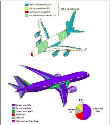
Composites offer a great advantages as a material for aircraft. It has a high strength
to weight ratio which significantly reduced the aircraft weight and thus are fuel save
(Aviation, 2005). Modern improved composite materials and matured processes have
encouraged commercial aircraft companies to increase the use of composites in
primary and secondary structures. Driven by the demand for fuel-efficient,
light-weight and high-stiffness structures that fatigue durable and corrosion
resistance, the Boeing 787 Dreamliner is designed with more than 50 percent
composite structure, marking a striking milestone in composite usage in commercial
Meanwhile, the Airbus A350 commercial airplane is being designed with a similar
percentage of composite materials in its structure. Figure 1 shows the use of
[image:18.595.136.504.151.565.2]composites in several commercial aircraft applications (Aniversario et al 1982).
Figure 1.1. Composite Materials Applications in Commercial Aircraft (Aniversario, et al. 1982)
Generally composite are produced to near net shape, however it still have to undergo
finishing operation to meet the dimensional requirements for assembly with other
The common finishing operation in industry is edge trimming in which to remove the
excess material. Edge trimming can be done with conventional router machine or
with non-conventional machining process such as ultrasonic machining, laser
machining and abrasive water jet machining. Since non-conventional machining
processes have disadvantages like heat-affected zone and low material removal rate,
the preferred choices for trimming CFRP are with conventional router and abrasive
water jet machining (R.Teti, 2009). But due to the inhomogeneous nature of CFRP,
machining of composite materials becomes a major cause of concern in the industry
(Neebu, 2001).
During CFRP machining the strong anisotropic effect of carbon fibre will produce
unstable surface finish. Consequently, the need to machine CFRP both efficiently and
1.2 Problem Statement / Challenge in Machining CFRP Composites
In general, all of the basic composite parts are obtained using different
manufacturing processes, such as hand layup or automatic lay-up followed by
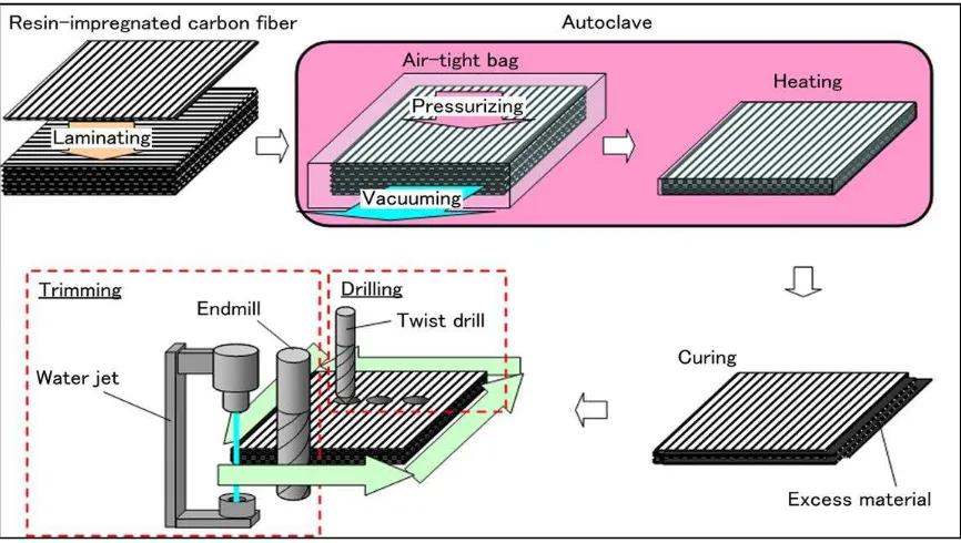
autoclave cure, RTM, or resin infusion. During the manufacture of the components
from carbon fibre reinforced plastic (CFRP), it is usually necessary to carry out a
post-machining step after curing in order to meet the required tolerances and to
manufacture fitting and joining surfaces. Classical production processes such as
milling and drilling are mainly used for this. Auto clave molding usually used to
manufactured CFRP part as shown in Figure 1.2 . Regardless of the production
process, damage in the form of delamination can occur during the processing of
CFRP. This characteristic production defect in CFRPs is particularly prevalent in the
top layers of the laminate as these are only supported on one side. Top and bottom
plies of a multiaxial CFRP tape are even more critical where crossing fibres are
mutually supported. The fibres are cut by the tool in an undefined way, deflect under
the action of the cutting edge and consequently delamination occurs in the form of
fibre overhang and fibre breakout at the cut edges. Such damage must be absolutely
avoided, because this requires time-consuming and costly post-machining to rectify
Figure 1.2 : Process to manufacture CFRP (Auto-clave molding)
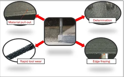
Despite the advances in near-net fabrication technologies, machining of CFRP
remains unavoidable to achieve the required dimensional tolerances and functional
surfaces for final assembly. Composite machining has been known to present a
myriad of issues such as rapid tool wear, fiber-pull outs, burrs, edge fraying, and
delaminations as shown in Figure 1.3. Due to the presence of highly abrasive fibers,
CFRPs are difficult to machine often resulting in damaged workpiece and high tool
wear rates. Most of the existing research in machining CFRP composite concentrates
merely on process planning and often neglects the effects of cutter geometric feature
which is significantly important. Tool geometric features such as helix angle have
direct influence on the cutting performance and should be seriously considered in
Figure 1.3 : Defects of CFRP
1.3 Objectives
Based on the problem encountered on machining CFRP composites, this project aim
to develop a new cutter geometry for effective machining of CFRP composites
material. The development of the new cutter consist of three steps:
a)Investigating the effect of cutter geometrical features which is right and left angle
for cross nick cutter on the surface roughness and delamination of CFRP
composites.
b)Optimizing the angle for right helix and left helix of the cutting tool in order to
obtain the minimum surface roughness and delamination when machining CFRP
composites.
c)To validate the effectiveness of the new propose cutter design on machining CFRP
1.4 Scope
Scope of the research :
i.Design improvement will focus on right and left helix angle.
ii.Using a statistical Response Surface Methodology to analyses the effect between
the factor (Right & Left helix angle) and the performance (surface roughness and
delamination).
CHAPTER 2
LITERATURE REVIEW
The study on machining CFRP composite involves many disciplinary areas such as
theories of machining, process and composite material. In this chapter, topics that
related to the development of the new cutter for trimming CFRP are reviewed. They
include the CFRP composite properties, machining, cutting tool, CFRP damage and
machining parameter. The purpose of reviewing these topics is to provide a
theoretical base for the remainder of the study.
2.1 CFRP Composites
Composite materials are made of two or more constituent materials that are different
in chemical structure and form. The main idea behind having two or more
constituents is to take the advantage of the favorable material properties of both,
without compensating for the weakness of either of the two materials (Ramakrishna
et al, 1999). The two phases of composite materials are matrix and reinforcement.
The matrix distributes load and forms a protective layer for the reinforcement.
However, the main advantage of composite materials over conventional metals and
alloys are their high specific strength and specific stiffness (Gordon et al, 2002).
The unique properties and applications of CFRP composites occupy a prominent
position of all FRP composite materials. It has useful functional and dimensional
properties that extend its applications to various domains. In the present research