UNIVERSITI TEKNIKAL MALAYSIA MELAKA
Robust Automated Guided Vehicle (AGV) Controller
Design Method For Uneven Terrains Application
This report is submitted in accordance with requirement of the Universiti Teknikal Malaysia Melaka (UTeM) for the Bachelor of Mechanical Engineering Technology
(Automotive Technology) with Honours
by
ADI KHAIRI BIN ABDUL LATIF B071210551
870330566189
UNIVERSITI TEKNIKAL MALAYSIA MELAKA
BORANG PENGESAHAN STATUS LAPORAN PROJEK SARJANA MUDA
TAJUK: Robust Automated Guided Vehicle (AGV) Controller Design Method For Uneven Terrain Application
SESI PENGAJIAN: 2014/2015 Semester 1
Saya ADI KHAIRI BIN ABDUL LATIF
mengaku membenarkan Laporan PSM ini disimpan di Universiti Teknikal Malaysia Melaka (UTeM) dengan syarat-syarat kegunaan sepert iberikut:
1. Laporan PSM adalah hak milik Universiti Teknikal Malaysia Melaka dan penulis. 2. Perpustakaan Universiti Teknikal Malaysia Melaka dibenarkan membuat salinan
untuk tujuan pengajian sahaja dengan izin penulis.
3. Perpustakaan dibenarkan membuat salinan laporan PSM ini sebagai bahan pertukaran antara institusi pengajian tinggi.
4. **Silatandakan ( ) sebagaimana yang termaktub dalam AKTA RAHSIA RASMI 1972)
(Mengandungi maklumat TERHAD yang telah ditentukan oleh organisasi/badan di mana penyelidikan dijalankan)
Alamat Tetap:
81 Jalan Wangsa 1 Wangsa Ukay,
Bukitantarabangsa 68000 Ampang,
Selangor Darul Ehsan.
Disahkan oleh:
Cop Rasmi:
**Jika laporan PSM ini SULIT atau TERHAD, sila lampirkan surat daripada pihak berkuasa/ organisasi berkenaan dengan menyatakan sekali sebab tempoh laporan PSM ini perlu dikelaskan sebahgai SULIT atau TERHAD
i
DECLARATION
I here by, declared this report entitled “Robust Automated Guided Vehicle (AGV) Controller Design Method For Uneven Terrains Application” is the results of my
own research except as cited in references
Signature :
ii
APPROVAL
This report is submitted to the Faculty of Engineering Technology of UTeM as a partial fulfillment of the requirements for the degree of Bachelor of Engineering Technology (JTKM) (Hons.). The member of the supervisory is as follow:
iii
ABSTRAK
iv
ABSTRACT
v
DEDICATION
vi
ACKNOWLEDGEMENT
vii
LIST OF ABBREVIATIONS, SYMBOLS AND NOMENCLATURE xiii
CHAPTER 1 1
1.1 Background of study 1
1.1.1 Wired AGV 2
1.1.2 Guide tape AGV 3
1.1.3 Laser target navigation AGV 3
1.1.4 Inertial (Gyroscopic) AGV 4
1.1.5 Vision guidance AGV 5
1.1.6 Natural features (natural targeting) AGV 5
1.1.7 Geo guidance AGV 6
1.2 Problem Statement 7
1.3 Objective 8
1.4 Scope 8
1.5 Structure of project 8
viii
2.1 Modelling 10
2.1.1 Kinematics Model of AGV 11
2.1.2 Camera Model of Image Processing 13
2.2 Controller 16
2.2.1 Feedback Controller 16
2.2.2 Feed-forward Controller 18
2.2.3 Linear Controller 19
Proportional Integral Derivative (PID) 21
Fuzzy Logic (FL) 23
2.2.4 Non-Linear Controller 24
Basic definitions of non-linear system 25
2.3 Techniques analysing non-linear feedback system based on project 27
2.3.1 Sontag’s Formula 28
2.3.2 Lyapunov Stability Analysis 30
Lyapunov’s Direct Method 33
Locally Positive Definite Function (LPDF) 33
Position Definite function (PDF) 33
Decrescent Functions (DF) 34
Lyapunov’s Indirect Method 34
2.3.3 Control Lyapunov Function (CLF) 37
2.3.4 Local Positioning System 39
ix
3.2.1 Flow Chart 46
3.3 Structure AGV development 47
3.3.1 CAE driven Conceptual Design 47
3.3.2 Structure Design 48
3.3.3 Structure Design Dimension 48
Basic Dimension 49
Pipe Rack General Dimension 49
Surface Dimension 50
Shaft, Base Model and Mounting Dimension 50
Bracket Dimension 51
3.4 AGV Electronic Component Specification 52
3.5 AGV Control System 55
3.6 Fabrication Process 56
3.7 Electronic Component Calibration 65
3.8 Interface of the Arduino software 67
3.9 Experiment on Automated Guided Vehicle (AGV) 69
3.9.1 Line following experiment on flat surface 69
3.92 Line following experiment on obstacle (outdoor) 70
CHAPTER 4 71
4.1 Flat surface result 71
4.2 Obstacle surface (outdoor) result 72
CHAPTER 5 73
5.1 Summary of conclusion 73
5.2 Futher Studies 73
x
LIST OF TABLES
3.1 Component specification 54
3.2 SOP Fabrication process 65
xi
LIST OF FIGURE
1.1 First AGV invented 1
1.2 Wired 2
1.3 Guide Tape 3
1.4 Laser targeting navigation 3
1.5 Inertial (Gyroscopic) 4
1.6 Vision guidance 5
1.7 Natural features (Natural targeting) 5
1.8 Geo guidance 6
2.1 AGV with two actuated wheel 11
2.2 Image plane in computer vision sensor 13
2.3 Block diagram feedback control 17
2.4 Block diagram feed forward control 18
2.5 PID controller 22
2.6 Precision and Significance decision making in real world 23
2.7 Equipment using Fuzzy Logic 23
2.8 Illustration of a pendulum 25
2.9 Linearization of a pendulum 27
2.10 Control signal magnitude using Sontag’s formula 29 2.11 Phase portrait Stable in the sense of Lyapunov 31
2.12 Phase portrait Asymptotically stable 32
2.13 Phase portrait Unstable 32
3.1 Flow chart 46
3.2 AGV conceptual design Hyperworks Optistruct 47 3.3 AGV structure design using Space Claim CAD 48
3.4 AGV basic dimension 49
3.5 Pipe rack general dimension 49
xii
3.7 Shaft, base model and mounting dimension 50
3.8 Bracket dimension 51
3.9 AGV control system 55
3.10 Arduino interface for motor testing 67
3.11 Flat surface experiment 68
3.12 Obstacle experiment 69
3.13 Flat surface graph 70
xiii
LIST OF ABBREVIATIONS, SYMBOLS AND
NOMENCLATURE
AGV - Automated Guided Vehicle
CLF - Control Lyapunov Function
IMU - Inertial Measurement Unit
LTI - Linear Time Invariant
PID - Proportional Integral Derivative
MV - Manipulated Variable
FL - Fuzzy Logic
DFM - Describing Function Method
SIDF - Sine Input Describing Function MIMO - Multiple Input Multiple Output
SPR - Strictly Positive Real
LPDF - Locally Positive Definite Function
PDF - Positive Definite Function
1
CHAPTER 1
INTRODUCTION
1.1 Background of study
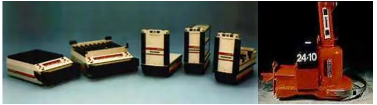
Automated Guided Vehicles (AGV) growth productivity and condense costs via assisting towards mechanise a manufacturing facility. AGV is Computer-controlled wheel-based cargo transporters that travel alongside the floor of a facility without a worker. They are typically battery powered. Their movement is engaged via arrangement of software and sensor-constructed control systems. Computer-based software uses wireless networks to gather information about each element’s present, formerly edges using software intended for end point and map-reading logic. The first inventor of Automated Guided Vehicle (AGV) are Barrett Electronics in 1953.
Figure 1.1 : First AGV invented
(http://www.egeminusa.com/pages/agv_education/education_agv_history.html)
2 programmed to interconnect with additional machines to guarantee the merchandise are been moved smoothly from end to end production line and the warehouse for storage or sent directly to shipping areas. There are many types of AGV navigation as well be discussed in this chapter.
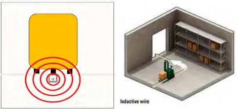
1.1.1 Wired AGV
Figure 1.2 : Wired (
http://www.transbotics.com/learning-center/guidance-navigation/)
3 1.1.2 Guide tape AGV
Figure 1.3 : Guide Tape (
http://www.transbotics.com/learning-center/guidance-navigation/ )
Some Automated Guided Vehicle (AGV) use duct tape for the direction. The duct tape can be magnetic or coloured. The Automated Guided Vehicle (AGV) is built-in with the suitable controller sensor to monitor the path of the duct tape. Main benefit of sticky tape over wired direction is that it can be simply detached and moved if the path changes. Coloured duct tape is primarily fewer expensive, but if the area of duct tape is always got moving the tape may become ruined or dirty. A flexible magnetic bar can also be implanted in the ground like wire but workings the same as magnetic tape. An additional benefit of magnetic conductor duct tape is the double polarity. Minor fragments of magnetic duct tape may be positioned to alteration conditions of the AGV based on polarization and arrangement.
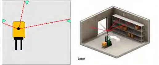
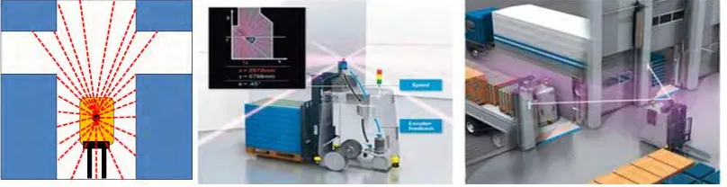
1.1.3 Laser target navigation AGV
Figure 1.4 : Laser target navigation (
4 The course plotting is completed by mounting tape on dividers, rods or machine. The AGV transmits a laser transmitter on a turning turret. The laser is transferred and received by the similar sensor. The angle and distance to any indicators that in reach are repeatedly calculated. This data is matched to the plot of the indicator plan kept in the AGV's memory. This lets the direction-finding system to triangulate the present location of the AGV. The present location is matched to the automated route in to the mirror design map. The navigation is attuned therefore to keep the AGV on track. It can then pilot to a wanted mark using the continuously renew position.
• Modulated lasers provides more noteworthy reach and precision over beat laser frameworks. By producing a non-stop modified laser, it can attain an uninterrupted image as soon as the scanner reaches line of range by a reflector. • Pulsed lasers produces beat laser light at a rate of 14,400 Hz which gives a
most extreme conceivable determination of ~ 3.5 mrad (0.2°) at 8 scanner cycles for each second. Towards attain a practical navigation, the evaluations must be exclaimed based on the concentration of the mirrored laser light, to recognize the core of the reflector.
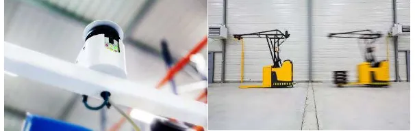
1.1.4 Inertial (Gyroscopic) AGV
Figure 1.5 : Inertial (Gyroscopic) (http://www.mhi.org/agvs)
5 measures vehicle’s and wheel encoder on the vehicle analyses the range travelled. Vehicle uses response from all manoeuvres to define location. Gyroscope is capable to sense the least alteration in the route of the vehicle and modifies it in order to retain the AGV on its route.
1.1.5 Vision guidance AGV
Figure 1.6 : Vision guidance (http://www.mhi.org/agvs)
Vision-Guided AGV mounted with no changes to the environment. It’s run via cameras to record geographies alongside the path, letting the AGV to repeat course by using the recorded geographies to steer. A conventional type of vision guided AGV is using processed image of colour marker as features on floor to navigate. This system can be implemented using sensor and open source microcontrollers which are generally cheap and easier to program.
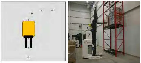
1.1.6 Natural features (natural targeting) AGV
6 Steering deprived of retrofitting of the working area is called Natural Features. The technique practices individual and additional range sensors. By Markov/Monte- Carlo localization methods to realize where it is as it vigorously strategize the direct pathway to destination. The benefit is that they are extremely flexible for on-time distribution at all places. It’s manage miscarriage deprived of shut down the whole engineering operation, since AGVs be able to design pathways everywhere the miscarried device. Fast to mount in a smaller amount of time for the factory.
1.1.7 Geo guidance AGV
Figure 1.8 : Geo guidance (http://www.balyo.com/en/Solution/Geoguidance )
7
1.2 Problem Statement
AGV are more efficient, consistent and productive than human operator but AGV are facing problem in maneuvering on slippery surface and cannot perform really well on uneven terrain or broken floors. This is due to AGV controller design that were using linear system, where in the real world the system is in non-linear (Hedrick & Girard, 2005). The problem faced by most AGV application in the industry are;
1. AGV design is sometime bigger and heavier than the product it is carry, which is not good in the term of energy efficiency and its moving speed.
2. Some AGV cannot perform well on rough terrain condition such as uneven terrain, slippery or broken floors.
3. Some AGV can only perform in controlled, indoor position while there are situation of using AGV at outdoor for transportation between plant.
8
1.3 Objective
1) To fabricate AGV body based on design given.
2) To design AGV controller for uneven terrain application. 3) To conduct experiment using the image based CLF controller.
1.4 Scope
Overall scope of this project are stated as below:
1) AGV design using Space Claim (CAD software). 2) AGV body fabrication using pipe joint system.
3) Camera and other components functions programming and calibration. 4) CLF controller implementation in AGV.
5) Experiment will be done on flat and obstacle surface, location area within the Kampus Teknologi, UTeM.
6) Gathering the experimental data of CLF controller with suitable gain parameter.
1.5 Structure of project
Chapter 1 will be the Introduction of Automated Guided Vehicle (AGV), the ongoing research to explain more deeply the meaning of AGV system and fragments found in AGV system. This chapter also states the problems of the AGV system and project objective that are clearly stated in this chapter to gain data the data from experiment at the end of the research. Other than that, project scope are described in detail in order to help the research on going in limited time.
9 Then chapter 3 will explain more about the methodology design of the AGV by showing the flow chart process and describe it in detail. The method flow from CAE generated conceptual design of AGV structure, CAD design of AGV, procedure of bodywork AGV fabrication, procedure of components and fabrication as well as programming CLF controller and experiment to be conducted.
Result and discussion of experiment findings are described in chapter 4. Discussion about the result analysis that are collected from the experiment are plotted in graph. The data that are collected during experiment need to be discussed and evaluated whether the objectives are achieved.