UNIVERSITI TEKNIKAL MALAYSIA MELAKA
OBSTACLE AVOIDANCE METHOD FOR AUTOMATED GUIDED
VEHICLE (AGV)
This report submitted in accordance with requirement of the Universiti Teknikal Malaysia Melaka (UTeM) for the Bachelor Degree of Manufacturing Engineering
(Robotics and Automation) with Honours.
by
NASHRUL ADZIM B. NASHRUDDIN
DECLARATION
I hereby, declared this report entitled “Obstacle Avoidance Method For Automated Guided Vehicle (AGV)” is the results of my own research except as cited in
references.
Signature : ………..
Author’s name : ………..
APPROVAL
This report is submitted to the Faculty of Manufacturing Engineering of UTeM as a partial fulfillment of the requirements for the degree of Bachelor of Manufacturing Engineering (Robotics and Automation) with Honours. The member of the supervisory committee is as follow:
(Signature of Supervisor)
………..
APPROVAL
This report is submitted to the Faculty of Manufacturing Engineering of UTeM as a partial fulfillment of the requirements for the degree of Bachelor of Manufacturing Engineering (Robotics and Automation) with Honours. The member of the supervisory committee is as follow:
(Signature of Principal Supervisor)
………..
(Official Stamp of Principal Supervisor)
(Signature of Co-Supervisor)
………..
ABSTRACT
ABSTRAK
ACKNOWLEDGEMENT
I would like to thank to ALLAH S.W.T because of His help author could finished this report. I also like to thank my supervisor, En. Mohd Hisham b. Nordin because of his supervision for the report writing and the PSM development progress. As for ISUZU HICOM Malaysia Sdn. Bhd. (IHMSB), the place where author learned about AGV, a great thank because allowing author to take AGV project as PSM project. Last but not least to all author family, especially author’s parent and sibling whose give a lot of support for this PSM project, IHMSB Engineering Department, Production Engineering (PE) section, Kaizen branch (Engineering Workshop) technician, ISUZU technician and anyone who is directly or indirectly involved in this PSM project.
TABLE OF CONTENT
2.3.2 Knowledge Engineering 13
2.3.3 The Inference Engine 15
2.3.4 How Expert Systems Explain Their Reasoning 16
2.3.5 Confidence Estimates 17
2.4 Obstacle Avoidance Method 17
3.0 METHODOLOGY 20
3.1 Introduction 20
3.2 Development planning 21
3.2.1 PSM 1 Gantt Chart 21
3.2.2 PSM 2 Gantt Chart 22
3.2.3 Development Process Flowchart 23
3.2.4 Development Process Flowchart Explanation 24
3.2.5 Programming Flowchart for Path Planning and Obstacle Avoidance 25 3.2.6 Programming Flowchart for Path Planning and Obstacle Avoidance
Explanation 26
3.3.1.3 Aluminium Square Tube 30
3.3.2 Electrical and Electronic Parts 31
3.3.2.1 Multimeter 31
3.3.2.7 Light Emitting Diode (LED) 37
3.3.2.8 Transistor 38
3.3.2.9 Resistor 39
3.3.2.10 Potentiometer 40
3.3.2.11 Capacitor 41
3.3.2.12 Wire 42
3.3.2.13 Printed Circuit Board (PCB) 43
3.3.2.14 Voltage Regulator 44
3.3.2.15 Diode 45
3.4 Method of Manufacturing 46
3.4.1.1 Laser Cutting Machine 46
3.4.1.2 Lathe Machine 48
3.4.1.3 Milling Machine 49
3.4.1.4 Horizontal Bandsaw Machine 50
3.4.2 Soldering Method 51
3.5.1.1 Programming a PIC using C language 56
3.5.1.2 Compiler for C language 56
3.6 Conclusion 57
4.0 RESEARCH AND DEVELOPMENT 58
4.1 AGV platform development 58
4.1.1 Tire coupling design 59
4.1.1.1 Tire coupling machining process 61
4.1.2 AGV chassis design 63
4.1.2.1 AGV chassis fabrication 64
4.1.2.2 AGV chassis assembly 65
4.2 AGV electronic circuit development 66
4.2.1 Line sensor circuit 66
4.2.1.1 Line sensor circuit development 68
4.2.2 Obstacle sensor circuit 70
4.2.3 Motor driver circuit 74
4.3 Programming development 76
4.3.1 Operational flowchart for AGV 76
4.3.2 Programming flowchart for AGV 76
4.3.3 Write program using MPLAB IDE 79
4.3.4 Programming using C language 83
4.3.4.1 AGV logic input for programming 85
4.3.5 PIC programmer 86
4.4 Conclusion 92
5.0 RESULT AND DISCUSSION 93
6.0 CONCLUSION AND FUTURE WORK 107
REFERENCES 108
APPENDICES
A AGV Development Costing 110
LIST OF TABLES
LIST OF FIGURES
2.1 Towing AGV. 6
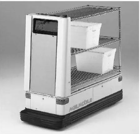
2.2 Packmobile® 4 and Carrier AGVs 6
2.3 ADAM (Autonomous Delivery and Manipulation) developed by
RMT Robotics. 7
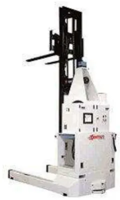
2.4 AGVs fork truck type. 7
2.5 Transcar Automated Guided Vehicle System (AGVs) used at Healthcare. 8
2.6 Automated tugger used for part delivery. 8
2.7 A basic schema for knowledge-based applications. 12
3.1 PSM 1 Gantt chart. 21
3.2 PSM 2 Gantt chart. 22
3.3 Flowchart for Development Process. 23
3.4 Flowchart for Path Planning and Obstacle Avoidance. 25
3.5 Drawing concept for AGV Platform. 27
3.6 Sponge tire. 28
3.7 Acrylic Glass for AGV Platform chassis. 29
3.8 Aluminium square tube. 30
3.9 Digital multimeter. 31
3.10 12 volt valve regulated lead-acid rechargeable battery. 32
3.11 12 volt geared dc motor. 33
3.12 PIC start up kit. 34
3.13 Both ultrasonic sensor transmitter and receiver. 35
3.14 A pair of IR detector and IR transmitter. 36
3.15 Variable colours and size of LED. 37
3.16 Typical transistor. 38
3.17 Variable value of resistor. 39
3.18 Typical potentiometer with variable resistive value. 40
3.19 Variable type and value of capacitor. 41
3.20 Variable hooked wire. 42
3.21 Parallel line PCB. 43
3.22 5 volt voltage regulator. 44
3.24 Laser cutting machine. 46
3.25 Lathe machine. 48
3.26 Milling machine. 49
3.27 Horizontal bandsaw machine. 50
3.28 Soldering iron. 51
3.29 Solder sucker. 52
3.30 Flux core solder inside a tube. 53
3.31 Automatic wire stripper. 54
4.1 Engineering drawing of tire coupling 60
4.2 Aluminium solid rod that have been cut to make tire coupling 61 4.3 Aluminium solid rod that has been done facing process 61 4.4 Turning process to the aluminium solid rod is done to form tire
coupling shape 61
4.5 Tire coupling with desire shape 61
4.6 Hole is drill to make the tire mounting hole screw 62
4.7 Hole is drill for motor shaft 62
4.8 Tire coupling 62
4.9 AGV chassis engineering drawing 63
4.10 Acrylic sheet is being cut using laser cutter machine 64
4.11 Parts of AGV chassis 64
4.12 Finished AGV frame 64
4.13 Assemble of motor to the AGV chassis 65
4.14 Half process of AGV chassis assembly 65
4.15 Complete AGV chassis 65
4.16 The basic voltage comparator 67
4.17 Line sensor circuit 67
4.18 Circuit that have been printed on OHP transparency paper 68
4.19 PCB is cut to the circuit size 68
4.20 Iron is used to transfer heat to the PCB for about 9 to 12 minutes 68
4.21 Ferric Chloride acid for etching process 69
4.22 Infrared transducer circuit is soldered with infrared
transmitter and receiver 69
4.23 Completed line sensor circuit 69
4.25 Ultrasonic transducer 71 4.26 Ultrasonic transducer circuit that have been attached to the AGV 71
4.27 Oscillator circuit design using Proteus 72
4.28 Ultrasonic transmitter circuit from protoboard 73
4.29 Ultrasonic receiver circuit 73
4.30 Ultrasonic receiver circuit from protoboard 74
4.31 Motor driver circuit designed from Proteus 75
4.32 Motor driver circuit is soldered on the independent board 75
4.33 Operational flowchart for AGV 77
4.34 Programming flowchart for AGV 78
4.35 MPLAB IDE 79
4.36 A programming from C language 80
4.37 Project Wizard to start a new project 80
4.38 Select type of PIC to use for the project 81
4.39 Select toolsuite language 81
4.40 Name of the project and file location 82
4.47 Build All the C source programming to get the hex file 88
4.48 Winpic800 version 3.55f 89
4.49 Open the hex file 89
4.50 PIC is detected from Winpic800 90
4.51 Setting configuration display 90
4.52 Setting to the configuration 91
4.53 Hex file have been burned inside the PIC16F877A 91
5.1 AGV fully function 93
5.2 Minimum distance of ultrasonic transducer to function properly 95
5.3 Maximum distance of ultrasonic detection 95
5.6 A paper have been place horizontally in front of ultrasonic transducer 96
5.7 Ultrasonic transducer can reflect a wave if the object is below the transducer 96
5.14 Two LEDs is light up indicates that line sensor sensing a straight aluminium line 99
5.15 Right LED is light up indicates that line sensor sensing right position of aluminium line 99
LIST OF ABBREVIATIONS
AC - Alternate Current
ADAM - Autonomous Delivery and Manipulation AGV - Automated Guided Vehicle
BORIS - Block Oriented Simulation System CPU - Central Processing Unit
D.C. - Direct Current DMM - Digital Multimeter
EEPROM - Electrical Erasable-programmable Read Only Memory FMS - Flexible Manufacturing System
HICOM - Heavy Industry Company of Malaysia I / O - Input / Output
Ga/As - Gallium Arsenide
GaAsP - Gallium Arsenide Phosphide
GaP - Gallium Phosphide
PIC - Peripheral Interfaces Controllers PID - Proportional Integral Differential
RAM - Random Access Memory
ROM - Read Only Memory
RPM - Revolution per Minute VOM - Volt / Ohm Meter
CHAPTER 1
INTRODUCTION
1.1 Project Introduction
1.2 Objective
Objectives of this project:
To learn and understand what is Automated Guided Vehicle (AGV).
To develop basic mobile robot platform represented as AGV.
To develop electronics circuit for AGV.
To develop AGV programming for obstacle avoidance method.
1.3 Scope
Scope that is covered for this project:
Mechanical design for AGV platform.
Mechatronics for AGV circuits.
Sensors for AGV.
Programming language for PIC.
1.4 Problem statement
From the industrial training experienced, author has been involved in a kit delivery project for chassis A and B assembly line at Isuzu HICOM Malaysia Sdn. Bhd. The project is mainly involved in constructing a guide tape made for two automated guided vehicle (AGV) which the company bought from Japan. These two AGVs were modified at Engineering Workshop so that it becomes a towing AGV. The main task of the AGV is to deliver a kit dolly rack that is filled with assembly components for HICOM Perkasa truck and ISUZU D-MAX pickup. However, there are a few problems and shortage encounter by both AGV such as being hitting by a transverser,
can’t move backward, do not move automatically after an operator from the assembly line pick the rack, non path planning programming, non obstacle avoidance programming, non sequence programming and missing guide tape on the floor. All of these problems sometimes delay the delivery routine. Operators have to replace the delivery task if any of the problems occurred to the AGV. Since the company reduces the workman power, the used of AGV is really necessary and reliable for delivery task. AGV is a costing mobile robot where a basic AGV can cost for almost RM5000 for industrial applications. Thus to reduce the cost, the company is planning to build its own AGV from scratch (refer Appendix A for project cost).
1.5 Conclusion
CHAPTER 2
LITERATURE REVIEW
2.1 What is AGV?
Automated guided vehicle, or AGV, are intended to be the most flexible conveyer
system possibleμ a conveyer which doesn’t need a continuous belt or roller table.
Ideally an AGV would be able to pick up a bin of parts or manufactured items and deliver them as needed. For example, an AGV might receive a bin containing an assembled engine. It could then deliver it automatically across the shop floor to the car assembly area which needed an engine. As it returned, it might be diverted by the central computer and instructed
However, navigation is complex. The AGV has to know where it is, plan a path from its current location to its goal destination, and avoid colliding with people, other AGVs, and maintenance workers and tools cluttering the factory floor. This proved too difficult to do, especially for factories with uneven lighting (which interferes with vision) and lots of metal (which interferers with radio controllers and on-board radar and sonar). Various solutions converged on creating a trail for the AGV to follow. One method is to bury a magnetic wire in the floor for the AGV to sense. Unfortunately, changing the path of an AGV required ripping up the concrete floor.
This didn’t help with the flexibility needs of modern manufacturing. Another method
be unable to detect an expensive piece of equipment or a person put deliberately in
its path. A few costly collisions would usually lead to the AGV’s removal. If the
AGV did have range sensors, it would stop for anything. A well placed lunch box could hold the AGV for hours until a manager happened to notice what was going on.
Even better from disgruntled worker’s perspective, many AGVs would make a loud
noise to indicate the path was blocked. Imagine having to constantly remove lunch boxes from the path of a dumb machine making unpleasant siren noises.
From the first, robots in the workplace triggered a backlash. Many of the human workers felt threatened by a potential loss of jobs, even though the jobs being mechanized were often menial or dangerous. This was particularly true of manufacturing facilities which were unionized. One engineer reported that on the first day it was used in a hospital, a HelpMate Robotics cart was discovered pushed down the stairs. Future models were modified to have some mechanisms to prevent malicious acts (Murphy 2000).
2.2 Types of AGV
AGVS Towing Vehicles were the first type introduced and are still a very
popular type today. Towing vehicles can pull a multitude of trailer types and have capacities ranging from 3628 kilogram to 27215 kilogram.
AGVS Unit Load Vehicles are equipped with decks, which permit unit load
transportation and often automatic load transfer. The decks can either be lift and lower type, powered or non-powered roller, chain or belt decks or custom decks with multiple compartments.
AGVS Pallet Trucks are designed to transport palletized loads to and form
floor level; eliminating the need for fixed load stands.
AGVS Fork Truck has the ability to service loads both at floor level and on
Light Load AGVS are vehicles which have capacities in the neighbourhood of
226 kilogram or less and are used to transport small parts, baskets, or light loads though a light manufacturing environment. They are designed to operate in areas with limited space.
AGVS Assembly Line Vehicles are an adaptation of the light load AGVS for
applications involving serial assembly processes (Transbotic 2008).
Figure 2.1: Towing AGV (ISUZU HICOM Malaysia Sdn. Bhd. 2008).
Figure 2.3: ADAM (Autonomous Delivery and Manipulation) developed by RMT Robotics (RMT Robotics Ltd. 2008).