PERFORMANCE COMPARISON BETWEEN CNG AND PETROL FUEL IN INTERNAL COMBUSTION ENGINE
NADHIRA FATHIAH BINTI KAMARULZAMAN
UNIVERSITI TEKNIKAL MALAYSIA MELAKA
SUPERVISOR DECLARATION
“I hereby declare that I have read this thesis and in my opinion this thesis is sufficient in terms of scopes and quality for the award of the degree of Bachelor of Mechanical
Engineering (Automotive) (Honours.)”
Signature: ………...
Supervisor: DR MUSTHAFAH BIN MOHD TAHIR
PERFORMANCE COMPARISON BETWEEN CNG AND PETROL FUEL IN INTERNAL COMBUSTION ENGINE
NADHIRA FATHIAH BINTI KAMARULZAMAN
This report submitted in partial
fulfillment of the requirements for the award
Bachelor's Degree in Mechanical Engineering (Automotive) with honours
Faculty of Mechanical Engineering Universiti Teknikal Malaysia Melaka
DECLARATION
"I hereby declare that the work in this thesis is my own except for summaries and quotations which is have been duly acknowledged.”
Signature: ...
Author: NADHIRA FATHIAH BINTI KAMARULZAMAN
DEDICATION
ACKNOWLEDGEMENT
Alhamdulillah, praise to Allah S.W.T who gave me strength and ideas to commit with this research and thesis report. Next, billion thanks to my supervisor, Dr. Musthafah bin Mohd Tahir for the guide and support through my PSM 1 and 2, especially during report writing, experiment and when I have problems in understanding the research.
Moreover, I would like to record my gratitude to Master Student, Mr. Muhammad Syahir bin Ali and Mr. Muhammad Muhaimin bin Mohd Syafi’e for helping me conduct my experiment and taught me about how to run the simulation and how to analyse the data. They also helped me to understand the engine works, know all the parts on the engine and much more.
ABSTRAK
ABSTRACT
TABLE OF CONTENTS
CHAPTER CONTENT PAGE
DECLARATION i.
DEDICATION ii.
ACKNOWLEDGEMENT iii.
ABSTRAK iv.
ABSTRACT v.
TABLE OF CONTENTS vi.
LIST OF TABLES viii.
LIST OF FIGURES ix.
LIST OF APPENDICES xii.
CHAPTER I INTRODUCTION
1.0 Problem Statement 1
1.1 Objectives 2
1.2 Scopes Of Study 3
CHAPTER II LITERATURE REVIEW
2.0 Introduction 4
2.1 Internal Combustion Engine 5
2.2 Valve Timing 9
2.3 Transportation 14
2.4 Energy Consumption And Emission 15
2.5 Natural Gas Vehicle 16
2.6 Pre-Combustion Chamber 18
CHAPTER III METHODOLOGY
3.0 Introduction 22
3.1 PSM Project Flow 23
3.2 EY20D Engine 24
3.3 Valve Timing And Ignition Point 29
3.4 Gasoline Experiment 31
3.5 CNG Experiment 33
3.6 CNG With PCC Experiment 34
3.7 Brake Specific Fuel Consumption For Gasoline 35
3.8 Brake Specific Fuel Consumption For CNG 36
3.9 Brake Specific Fuel Consumption For CNG With PCC
37
CHAPTER IV RESULTS AND ANALYSIS
4.0 Valve Timing 38
4.1 Power And Torque 40
4.2 Pressure Inside Cylinder 43
4.3 Heat Release Inside Cylinder 47
4.4 Temperature Inside Cylinder 50
4.5 Cylinder Pressure Derivatives 54
4.6 Brake Specific Fuel Consumption 57
CHAPTER V CONCLUSION
5.0 Introduction 60
5.1 Conclusion 60
5.2 Recommendation 61
REFERENCES 62
LIST OF TABLES
TABLE NO CONTENT PAGE
2.0 Global Final Energy Consumption By Sector (IEA
.
2010) 152.1 Combustion Properties Of CNG Fuel And Gasoline Fuel 17
2.2 Common Sensor 21
3.0 Detail Specification Of Robin EY20D Engine
.
(Robin Industrial, 2000)25
3.1 Specification Of Water Sprayer Wuli W-45B Pump (Wuli Agriculture Machine Co, Ltd
.
, 2009)27
4.0 Gasoline Experimental Data 40
4.1 CNG Experimental Data 40
LIST OF FIGURES
FIGURE NO. CONTENT PAGE
2.0 The Two Stroke Cycle Engine (Harikrishnan, P
.
R.
2014) 62.1 The Four Stroke Cycle Engine (Halderman, J
.
D.
2012) 72.2 The Simplification Of The Engine Based On Type And
Operation
.
(Ganesan, V.
2010)8
2.3 Typical Valve Timing Diagram (SweetHaven, 1985) 9
2.4 Opening And Closing Point Of The Valve (SweetHaven,
1985)
10
2.5 Valve Opening Duration (SweetHaven, 1985) 10
2.6 Valve Timing Diagram With Valve Overlap In 4stroke
Engine (SweetHaven, 1985)
11
2.7 Valve Timing Diagram Showing Scavenging Period In
The 2Stroke Engine (Mathur And Sharma, 2000)
12
2.8 Rock Position (SweetHaven, 1985) 13
2.9 Cylinder Pressure In The Combustion Chamber Of An
SI Engine As Function Of Crank Angle.
13
2.10 Road Transport Vehicle Versus Years (Ong, H
.
C.
et al.
2012)14
2.11 Pre-Combustion Chamber 18
2.12 Data Acquisition 20
3.0 Flow Chart For CNG And Petrol Fuel Performance
Comparison PSM
23
3.1 EY20D Air Cooled Engine (Robin Industrial Engine
2000)
3.4 Overhaul Engine 28
3.5 Valve Timing Experiment Setup 29
3.6 Crank Rotation 29
3.7 Sensor Installation At The Engine Head 31
3.8 Sensor Installation At Crank Shaft 31
3.9 DAQ Analyser Connected To Computer 32
3.10 Gasoline Is Closed And CNG Are Opened 33
3.11 PCC Position 34
3.12 Fuel Are Inserted In The Burette 35
3.13 CNG Tank On The Weighing Scales 36
4.0 Graph Of Valve Timing With Respect To Crank
Rotation
38
4.1 Power Produces At Different Speed Of Gasoline, CNG
And CNG With PCC
41
4.2 Torque Produces At Different Speed Of Gasoline, CNG
And CNG With PCC
42
4.3 Pressure Inside Cylinder For 1500 rpm 43
4.4 Pressure Inside Cylinder For 2000 rpm 43
4.5 Pressure Inside Cylinder For 2500 rpm 44
4.6 Pressure Inside Cylinder For 3000 rpm 44
4.7 Pressure Inside Cylinder For 3500 rpm 45
4.8 Pressure Inside Cylinder For 4000 rpm 45
4.9 Heat Release Inside Cylinder For 1500 rpm 47
4.10 Heat Release Inside Cylinder For 2000 rpm 47
4.11 Heat Release Inside Cylinder For 2500 rpm 48
4.12 Heat Release Inside Cylinder For 3000 rpm 48
4.13 Heat Release Inside Cylinder For 3500 rpm 49
4.14 Heat Release Inside Cylinder For 4000 rpm 49
4.15 Temperature Inside Cylinder For 1500 rpm 50
4.16 Temperature Inside Cylinder For 2000 rpm 51
4.18 Temperature Inside Cylinder For 3000 rpm 52
4.19 Temperature Inside Cylinder For 3500 rpm 52
4.20 Temperature Inside Cylinder For 4000 rpm 53
4.21 Cylinder Pressure Derivatives For 1500 rpm 54
4.22 Cylinder Pressure Derivatives For 2000 rpm 54
4.23 Cylinder Pressure Derivatives For 2500 rpm 55
4.24 Cylinder Pressure Derivatives For 3000 rpm 55
4.25 Cylinder Pressure Derivatives For 3500 rpm 56
4.26 Cylinder Pressure Derivatives For 4000 rpm 56
4.27 Comparison Of Bsfc For Gasoline, CNG And CNG
With PCC
58
LIST OF APPENDICES
APPENDIX CONTENT
A Gantt Chart PSM 1
B Gantt Chart PSM 2
C Detail Drawing Of Robin EY20D Engine
D Gasoline Experiment Data
E CNG Experiment Data
F Detailed Drawing Of PCC Used In Experiment
CHAPTER I
INTRODUCTION
This chapter will roughly elaborate about the advantage of the Compress Natural Gas (CNG), why this kind of fuel is chosen and the problem in the combustion that needs to be studied and improve so that the CNG can be better compared to gasoline and diesel. The scope of this project is generated based the objective given.
1.0 PROBLEM STATEMENT
A regulation requiring clear burning in engine combustion, the Compressed Natural Gas (CNG) was introduced which is lower greenhouse gas emission compared to the gasoline (Petrol)
.
natural gas engine is the poor ignitibility of methane, a long and variable ignition delay is undesirable as it leads to sharp heat release and the CNG engine has high mechanical load due to an increased combustion in the premixed part (Zheng, Zhang, & Zhang, 2005)
.
Thus, the application of CNG systems into current vehicle nowadays needs a lot of improvement due to the performance of CNG engine compared to the gasoline fuel engine is lower with 20% difference
.
This power dropped might due to several factors needed to be studied in the combustion.
1.1 OBJECTIVES
The objectives needed to be done in order to complete this project are listed as follows:
1. To compare engine performance between two different types of fuel which is gasoline and Compressed Natural Gas
.
2. To study CNG combustion in the 4 stroke, single cylinder engine
.
3. To find the method to increase the CNG performance.1.2 SCOPES OF STUDY
CHAPTER II
LITERATURE REVIEW
2.0 OVERVIEW
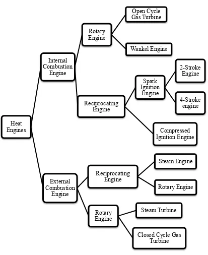
2.1 INTERNAL COMBUSTION ENGINE (ICE)
The Internal combustion engine is a heat engine that converts chemical energy in a fuel into mechanical energy, usually made available on a rotating output shaft
.
Due to the upward and downward movement of the piston and valve in it, internal combustion engine (ICE) also known as reciprocating engine.
The chemical energy of the fuel is first converted to thermal energy by means of combustion or oxidation with air inside the engine.
This thermal energy raises the temperature and pressure of the gases within the engine, and the high-pressure gas then expands against the mechanical mechanisms of the engine.
This expansion is converted by the mechanical linkages of the engine to a rotating crankshaft, which is the output of the engine.
The crankshaft, in turn, is connected to a transmission or power train to transmit the rotating mechanical energy to the desired final use.
Before modern engine is developed, heat engine has served human kind over two centuries by use steam energy as its power source.
two types, which is Spark ignition (SI) engine and compressed ignition (CI) engine
.
Spark ignition engine starts the combustion process in each cycle by use of a spark plug.
The spark plug gives a high-voltage electrical discharge between two electrodes which ignites the air-fuel mixture in the combustion chamber surrounding the plug.
Compressed ignition engine starts the combustion process when the air-fuel mixture self-ignites due to high temperature in the combustion caused by high compression.
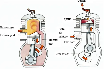
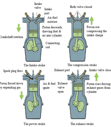
Combustion engine working principle can be divided into two types that are four stroke engine and two stroke engines.
(Heywood, JB.
1988) Four-stroke cycle has four piston movements over two engine revolution for each cycle meanwhile, two-stroke cycle has two piston movements over one revolution for each cycle.
Figure 2.1 : The four stroke cycle engine (Halderman, J
.
D.
2012)Piston descends, Drawing fuel and air into cylinder
Piston forced down by expanding gas
The power stroke The exhaust stroke
Spark plug fires Exhaust port
Piston forced down
by expending gas Exhaust valve
open
valve Both valve closed
Piston rise compressing the intake charge Crankshaft rotation
The compression stroke
The power stroke The exhaust stroke
2.2 VALVE TIMING
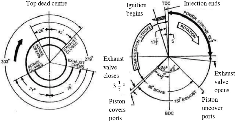
Figure 2.3 : Typical valve timing diagram (SweetHaven, 1985)
The valve timing is a system developed for measuring valve operation in relation to crankshaft position (in degrees), particularly the points when the valves open, how long they remain open, and when they close
.
Valve timing of 4stroke and 2stroke engine can be visualized as shown in Figure 2.
3.
Valve timing is one of the most important factors in tailoring an engine for special needs
.
An engine can be made to produce its maximum power in various speed ranges by altering the valve timing (SweetHaven, 1985).
Piston
4-stroke valve timing diagram 2-stroke valve timing diagram