ANALYSIS OF PNEUMATIC VALVE CONTROL
SYSTEM
NOR SURIYANTI BINTI OSMAN
B051110084
UNIVERSITI TEKNIKAL MALAYSIA MELAKA
ANALYSIS OF PNEUMATIC VALVE CONTROL SYSTEM
This report submitted in accordance with requirement of the Universiti Teknikal Malaysia Melaka (UTeM) for the Bachelor Degree of Manufacturing Engineering
(Robotics and Automation) (Hons).
by
NOR SURIYANTI BINTI OSMAN B051110084
920101-04-5518
DECLARATION
I hereby, declared this report entitled Analysis of Pneumatic Valve Control System is the results of my own research except as cited in references.
Signature : ……….
Author’s Name : ………
Date : ………
APPROVAL
This report is submitted to the Faculty of Manufacturing Engineering of UTeM as a partial fulfillment of the requirements for the degree of Bachelor of Manufacturing Engineering (Robotic and Automation) (Hons.). The member of the supervisory is as follow:
UNIVERSITI TEKNIKAL MALAYSIA MELAKA
1. Laporan PSM adalah hak milik Universiti Teknikal Malaysia Melaka dan penulis. 2. Perpustakaan Universiti Teknikal Malaysia Melaka dibenarkan membuat salinanuntuk tujuan pengajian sahaja dengan izin penulis.
3. Perpustakaan dibenarkan membuat salinan laporan PSM ini sebagai bahan pertukaran antara institusi pengajian tinggi.
i
ABSTRAK
ii
ABSTRACT
iii
DEDICATION
iv
ACKNOWLEDGEMENT
First of all, I am grateful to The Almighty God for establishing me to complete this final year project.
I would like to express the deepest appreciation to all coordinators who give me the opportunity to do my final year project in Universiti Teknikal Malaysia Melaka (UTeM), Melaka, Malaysia.
I place on record, my sincere gratitude to my principle supervisor, Dr. Ahmad Yusairi bin Bani Hashim, my project supervisor from Manufacturing Engineering (Robotic and Automation) Department for his constant encouragement. I am extremely grateful and indebted to him for his expertise, sincere and valuable guidance.
In addition, I would like to take this opportunity to record my sincere thanks to all lectures from UTeM, Melaka, Malaysia especially in Manufacturing Engineering (Robotic and Automation) Department, my senior; Miss Sufiah Akmala binti Ramdan, and all technician in UTeM for their help and encouragement.
vii
2.5.1.8 Lumped Parameter and Distributed Parameter Control Systems 25 2.5.1.9 Single Input Single Output (SISO) and Multiple Input Multiple Output (MIMO) 26 2.5.1.10 Open Loop and Closed Loop System 26
2.5.2 Basic Steps to Design a Control System 26 2.5.3 Mathematical Model of Control System 27 3.4 Phase 1: Identification of the DCV Basics 35 3.4.1 Step 1: The Type of Pneumatic DCV Used 36
3.4.2 Step 2: The Working Principle of Pneumatic DCV 36
3.4.3 Step 3: The Pneumatic DCV Construction 36
3.4.4 Step 4: The Parameter for both Electromagnetic and Mechanical Subsystem 37 3.5 Phase 2: Modelling the Control System of the DCV 37
3.5.1 Step 1: The Block Diagrams of Pneumatic DCV 37
viii
ix
APPENDICES 66
A.Pneumatic Symbols 67
B. Common Command Matrix Operators
Relational and Logical Operators Special Characters
73
C. Experiment 1- Identification the DCV Basics
Experiment 2 - Modelling the Control System of DCV Experiment 3 - Evaluation of DCV Control System Experiment 4 - Pneuamtic Test Procedure
76
D. MATLAB Program
Air Flow Rate Calculation
84
E. 5/2 Way Double Solenoid Valve Drawing 94
x
LIST OF TABLES
1.1 Developments on pneumatic valve 2
1.2 Pneumatic valve issues 3
1.3 Input and output signal parameter 3
2.1 Power and signal element components
4.1 Specification of Pneumatic Valve 4.2 List of Pneumatic Valve Part
4.3 Electromagnetic Subsystem Parameter of 5/2-Way Double Solenoid Valve
4.4 Mechanical Subsystem Parameter of 5/2-Way Double Solenoid Valve 4.5 Specification of Pneumatic Valve
A.2 Symbol of Air Preparation Units, Pneumatic Valves 68
A.3 Actuation Variation with Symbols 70
A.4 Symbol of Lines and Functions 71
B.1 MATLAB Commands and Predefined Functions 74
B.2 MATLAB Matrix Operators with Predefined Operations 75 B.3 Relational and Logical Operators that Used in MATLAB 75 B.4 Special Characters that Used in MATLAB
C.4 Pneumatic Valve Performance
76
xi
2.6 Two directional control valve with extend condition 15 2.7 Two directional control valve with retract condition 16
2.8 Poppet type valve 17
2.14 Five ported, 4-way directional valve 19
2.15 Position approaches 20
2.16 Spring offset symbol 21
2.17 Detent symbol 21
2.18 Schematic installation of the pneumatic system 23
2.19 Basic steps in designing of control system 27
2.20 Schematic diagram of the spool valve structure 29
3.1 Flow chart of overall report methodology 35
3.2 Main working principle of pneumatic 36
xii
4.1 Double Solenoid, Spool-Sliding Type Valve 4.2 Working Principle of DCV
4.3 Block Diagram of Electromagnetic Subsystem with Voltage (V) as Input and Magnetic Force (F) as its Output
4.4 Block Diagram of Mechanical Subsystem with Magnetic Force, (F) as Input and Spool Movement, (X) as its Output
4.5 Free Body Diagram of Electromagnetic Subsystem 4.6 Free Body Diagram of Electrical System
4.7 Free Body Diagram of Magnetic System 4.8 Free Body Diagram of Mechanical Subsystem 4.9 Free Body Diagram of Mechanical Subsystem
4.10 Step Response of 5/2-Way Pneumatic Valve using Transfer Function in Electromagnetic Subsystem
4.11 Step Response of 5/2-Way Pneumatic Valve using Transfer Function in Mechanical Subsystem
4.12 Nyquist of 5/2 Way Pneumatic Valve using Transfer Function in Mechanical Subsystem
4.13 Air flow rate of 5/2 Way Double Solenoid Valve with Three Different Pressure: 29.01, 43.51 and 58.02 PSIA
4.14 Response Rate of 5/2 Way Double Solenoid Valve with Three Different Pressure: 29.01, 43.51 and 58.02 PSIA
xiii
LIST OF ABBREVIATIONS, SYMBOLS AND
NOMENCLATURE
DCV - Directional Control Valve
FYP
-
Final Year ProjectFBD
-
Free Body DiagramFRL
-
Filter, Regulator and LubricatorMax
-
MaximumMIMO
-
Multiple Input Multiple OutputSISO
-
Single Input Single OutputSCFM
-
Standard Cubic Feet Per MinutePSIA
-
Pounds Per Square Inch Absolute1
CHAPTER 1
INTRODUCTION
This chapter describes the introduction of the project of pneumatic valve control system. Begin with the introduction to current issues, followed by translation of the problem statement from the questions and identification of project objectives. Next, project scope and report organization will be discussed. Lastly, Gantt chart will be covered in this chapter.
1.1Background
Pneumatic is one of the power sources that is widely used in automated machine equipment in performing various automation projects. Most of the industries prefer to use pneumatic because it is simple, cheap, easy to handle and maintenance and possesses a high level of controllability. In addition, pneumatic medium; the air are widely available and compressible (Majumdar, 1996).
In pneumatic system, pneumatic valve is a vital mechanical component. The Romans first founded the valve concept. They used bronze plug as cock in their aqueducts (Borden, 1998). In general, valve consists of a body and a moving part which control air passages within the body. The moving part is essential in controlling system pressure, direction of flow and rate of flow in the system.
2
The evolution of complex processes in industries and necessity to reduce production cost, a study approach is required to monitor the valve operating condition. Thus, it is important for engineers to analyze significant issues of the pneumatic valve to prevent the pneumatic valve from the damaged working condition. Several new methods have been implemented to maintain the pneumatic valve in good condition.
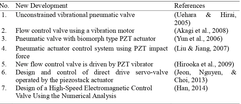
Table 1.1: Developments on pneumatic valve
No. New Development References
1. Unconstrained vibrational pneumatic valve (Uehara & Hirai, 2005)
2. Flow control valve using a vibration motor (Akagi et al., 2008) 3. Pneumatic valve with biomorph type PZT actuator (Yun et al., 2006) 4. Pneumatic actuator control system using PZT impact
force (Liu & Jiang, 2007)
5. New flow control valve is driven by PZT vibrator (Hirooka et al., 2009) 6. Design and control of direct drive servo-valve
operated by the piezostack actuator (Jeon, Nguyen, & Choi, 2013) 7. Design of a High-Speed Electromagnetic Control
Valve Using the Numerical Analysis (Han, 2014)
3
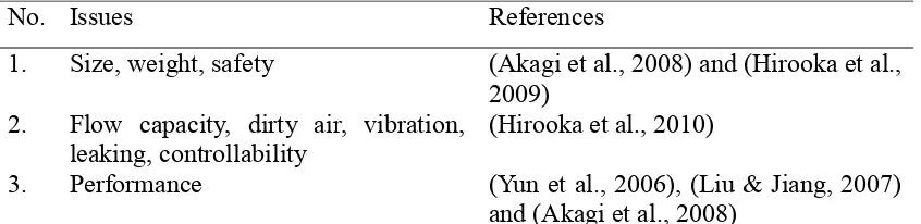
Table 1.2: Pneumatic valve issues
However, there is problem on size, weight, safety (Akagi et al., 2008) and (Hirooka et al., 2009), flow capacity, dirty air, vibration, leaking, controllability (Hirooka, Suzumori, & Kanda, 2010) and performance in pneumatic valve system (Yun et al., 2006), (Liu & Jiang, 2007) and (Akagi et al., 2008) as stated in Table 1.2.
Analyzing pneumatic valve control system has attracted considerable work to enhance its responsiveness based on the design of pneumatic valve and input signal parameter in this project. The pneumatic valve control system will be studied by utilizing basic information and control system of pneumatic valve and evaluation using both MATLAB and experiment.
4
1.2Problem Statement
Directional control valve (DCV) has been widely used in industry in various applications. The increasing of the complex process and the necessity to scale down production cost has increased the demand on the good quality valve. Hence, it is important for engineers or designers to develop new methods of managing pneumatic valve issues. Size, weight, current capacity, dirty air, vibration, leaking, controllability and performance are the most frequently recorded issue on the pneumatic valve. This project intends to analyze the pneumatic valve control system to get an advance understanding in several typical valve issues that may cut system setup time and attain more precise motion.
1.3Objectives
The objectives of this project are to: a) Identify the DCV,
b) Model the control system of the DCV, and c) Evaluate the DCV control system.
1.4Scope
5
1.5Organization of Report
The beginning chapter of this report describes the introduction of the pneumatic valve control system. It is followed by the description of the literature review. Next, this report proceeds with the explanation of the methodology used. Subsequently, the next chapter elaborates the results and discussion. In the end, the last chapter discusses the conclusions and recommendations of this report.
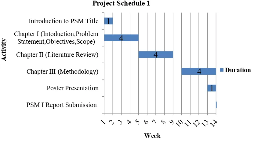
1.6Gantt Chart
6
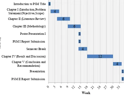
1.6.2 Project Schedule 2
Figure 1.2: Project Schedule 2
1.6.3 Project Schedule for Entire Project (Project 1 and 2)
Figure 1.3: Project Schedule For Entire Project (Project 1 and 2)