UNIVERSITI TEKNIKAL MALAYSIA MELAKA
DESIGN AND DEVELOPMENT OF SUSTAINABLE FILAMENT
EXTRUDER FOR 3D PRINTER
This report submitted in accordance with requirement of the Universiti Teknikal Malaysia Melaka (UTeM) for the Bachelor Degree of Manufacturing Engineering
Technology (Product Design) With Honors
by
LEONG YONG LIM B071210402 911227-14-5165
UNIVERSITI TEKNIKAL MALAYSIA MELAKA
BORANG PENGESAHAN STATUS LAPORAN PROJEK SARJANA MUDA
TAJUK: Design and Development of Sustainable Filament Extruder for 3D Printer
SESI PENGAJIAN: 2015/16 Semester 1
Saya LEONG YONG LIM
mengaku membenarkan Laporan PSM ini disimpan di Perpustakaan Universiti Teknikal Malaysia Melaka (UTeM) dengan syarat-syarat kegunaan seperti berikut:
1. Laporan PSM adalah hak milik Universiti Teknikal Malaysia Melaka dan penulis. 2. Perpustakaan Universiti Teknikal Malaysia Melaka dibenarkan membuat salinan
untuk tujuan pengajian sahaja dengan izin penulis.
3. Perpustakaan dibenarkan membuat salinan laporan PSM ini sebagai bahan pertukaran antara institusi pengajian tinggi.
4. **Sila tandakan ( )
SULIT
TERHAD
TIDAK TERHAD
(Mengandungi maklumat yang berdarjah keselamatan atau kepentingan Malaysia sebagaimana yang termaktub dalam AKTA RAHSIA RASMI 1972)
(Mengandungi maklumat TERHAD yang telah ditentukan oleh organisasi/badan di mana penyelidikan dijalankan)
(TANDATANGAN PENULIS)
Alamat Tetap:
NO. 16, Jalan 1/140A,aaaaaaaaaaaa
Perkasa Tmn Salak Selatan aaaaaa
57100 Kuala Lumpur. aaaaaaaaaaaa
Tarikh: ________________________
Disahkan oleh:
(TANDATANGAN PENYELIA)
Cop Rasmi:
iii
DECLARATION
I hereby, declared this report entitled “Design and Development of Sustainable Filament Extruder For 3D Printer” is the results of my own research except as
cited in references.
Signature :………
Name : ………
iv
APPROVAL
This report is submitted to the Faculty of Engineering Technology of UTeM as a partial fulfillment of the requirements for the degree of Bachelor of Manufacturing Engineering Technology (Product Design) With Honors. The member of the supervisory is as follow:
v
ABSTRACT
vi
ABSTRAK
vii
DEDICATIONS
viii
ACKNOWLEDGMENTS
ix
TABLE OF CONTENTS
DECLARATION ... iii
APPROVAL ... iv
ABSTRACT ... v
ABSTRAK ... vi
DEDICATIONS ... vii
ACKNOWLEDGMENTS ... viii
TABLE OF CONTENTS ... ix
LIST OF FIGURES ... xiii
LIST OF TABLE ... xv
LIST OF SYMBOLS AND ABBREVIATIONS ... xvi
CHAPTER 1 ... 1
1.1 Background ... 1
1.2 Problem Statement ... 2
1.3 Objective ... 2
1.4 Scope of Work ... 3
CHAPTER 2 ... 4
2.1 Sustainability ... 4
2.1.1 Achievement of Sustainability ... 5
2.1.2 Open-loop Material Cycle ... 5
x
2.1.4.1 Design Optimization ... 7
2.1.5 Design for Sustainable Disposal ... 7
2.1.5.1 Recycling ... 8
2.2 3D Printing ... 10
2.2.1 Fused Deposition Modelling ... 10
2.2.2 Operation of FDM ... 11
2.2.3 Mechanisms of FDM printer ... 13
2.2.3.1 Inductive Heating of FDM Extruder ... 14
2.2.4 3D Printing Filament Materials ... 14
2.3 Rapid Prototyping ... 16
2.3.1 Application of Rapid Prototyping in Industry ... 16
2.3.2 Advantages and Limitations ... 18
2.4 Filament Extruder ... 18
2.4.1 Working Principles of Filament Extruder ... 18
2.4.1.1 Lyman Filament Extruder ... 19
2.4.1.2 STRUdittle Extruder ... 21
2.4.1.3 ProtoCycler Desktop Filament Extruder... 22
2.4.1.4 Design Comparison... 24
2.4.2 Creative Commons (CC) License ... 25
2.4.3 Patent ... 26
CHAPTER 3 ... 27
xi
3.2 Project Planning Process ... 27
3.3 Flow Chart of Process ... 28
3.3.1 Project Proposal and Research For Project ... 29
3.3.2 Design Approach ... 29
3.3.2.1 Conceptual Design ... 30
3.3.2.2 Design Selections ... 33
3.3.2.3 Part Design and Assembly ... 33
3.3.2.4 Bill of Materials (B.O.M) ... 35
3.4 Filament Extruder Prototype Machining ... 36
3.4.1 Sheet Metal Fabrication ... 36
3.4.1.1 Water Jet Cutting ... 36
3.4.1.2 Shear Cutting ... 37
3.4.1.3 Sheet Metal Bending ... 38
3.4.2 Metal Cutting ... 38
3.4.3 Lathe ... 39
3.4.4 Drilling ... 39
3.4.5 Threading ... 40
3.4.6 3D Printing ... 41
3.4.7 Painting ... 41
3.4.8 Summary ... 42
3.5 Filament Extruder Electronic Component Wiring ... 43
3.5.1 Motor Wiring System ... 43
xii
4.1 Design Results ... 45
4.1.1 Filament Extruder Part Design ... 45
4.1.2 Filament Extruder Final Assembly ... 49
4.2 Final Results ... 50
4.2.1 Part Fabrication and Purchased Items ... 50
4.2.2 Final Prototype of Filament Extruder ... 54
4.2.3 Discissions ... 55
4.2.4 Material Selections ... 55
4.2.5 Electronic Components Selections ... 57
4.2.5.1 DC Components ... 57
4.2.5.2 AC Components ... 57
CHAPTER 5 ... 59
5.1 Conclusions ... 59
5.2 Future Works Recommendation ... 60
5.2.1 Summary of Research ... 60
APPENDIX A ... 62
APPENDIX B……….. 64
xiii
LIST OF FIGURES
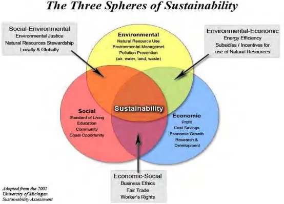
Figure 2.1: The triple bottom line of sustainability... 4
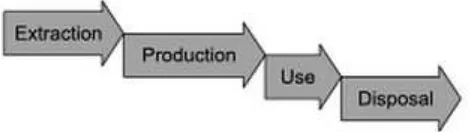
Figure 2.2: Open-Loop Material Cycle ... 5
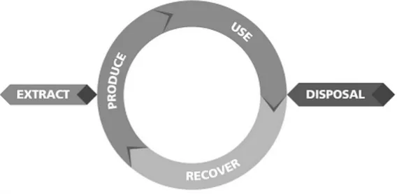
Figure 2.3: Closed-loop material cycle ... 6
Figure 2.4: Model for End-of-Life Decision Action ... 8
Figure 2.5: 3D Touch 3D printer ... 10
Figure 2.6: Fused deposition modelling ... 11
Figure 2.7: Operation of FDM ... 12
Figure 2.8: Mechanisms of filament extrusion ... 13
Figure 2.9: Mechanisms of filament extrusion head of 3D printer ... 13
Figure 2.10: Mechanisms of filament heater... 14
Figure 2.11: 3D printer Filaments ... 15
Figure 2.12: Exterior view of Mark Prototype Inc. ... 16
Figure 2.13: FDM machine Figure 2.14: Prototyping parts ... 17
Figure 2.15: Rapid Prototyping Process Chain ... 17
Figure 2.16: Working principle of filament extruder ... 19
Figure 2.17: Hugh Lyman Extruder ... 19
Figure 2.18: Mechanism of STRUdittle Extruder ... 21
Figure 2.19: Exploded view of STRUdittle Extruder ... 22
Figure 2.20: ProtoCycler ... 22
Figure 3.1: Flow chart of process ... 28
Figure 3.2: Design 1 ... 30
Figure 3.3: Design 2 ... 31
Figure 3.4: Design 3 ... 32
Figure 3.5: The design overview of filament extruder ... 33
Figure 3.6: Exploded view of designed filament extruder ... 34
Figure 3.7: Detail drawing of sheet metal for cover and chamber support ... 36
Figure 3.8: Water jet machine ... 37
Figure 3.9: Shear cutting of sheet metal... 37
Figure 3.10: Bending machine ... 38
Figure 3.11: Bandsaw machine Figure 3.12: Hacksaw ... 38
Figure 3.13: Applying electrical mini hand grinder ... 39
Figure 3.14: Lathe machine and turning process ... 39
Figure 3.15: Milling machine Figure 3.16: Drilling machine ... 40
Figure 3.17: Treading process by using taps ... 40
Figure 3.18: Painting of the cover part and hopper ... 41
Figure 3.19: DC Motor wiring diagram ... 44
Figure 3.20: AC Heater wiring diagram ... 44
Figure 4.1: Chamber (3D Modelling) ... 45
xiv
Figure 4.4: Basement (3D Modelling) ... 45
Figure 4.5: Gear Motor (3D Modelling) ... 46
Figure 4.6: Motor Coupler (3D Modelling) ... 46
Figure 4.7: Motor Holder (3D Modelling) ... 46
Figure 4.8: Cover (3D Modelling) ... 46
Figure 4.9: Hopper (3D Modelling) ... 46
Figure 4.10: Nozzle (3D Modelling) ... 46
Figure 4.11: Bolt Screw (3D Modelling) ... 47
Figure 4.12: Bolt Nut (3D Modelling) ... 47
Figure 4.13: Allen Screw (3D Modelling) ... 47
Figure 4.14: Feed Screw (3D Modelling) ... 47
Figure 4.15: H608LL Bearing (3D Modelling)... 47
Figure 4.16: Digital Thermometer (3D Modelling) ... 47
Figure 4.17: Adapter (3D Modelling) ... 48
Figure 4.18: Heater Band (3D Modelling) ... 48
Figure 4.19: Thermostat (3D Modelling) ... 48
Figure 4.20: 3 Pin Plug (3D Modelling) ... 48
Figure 4.21: Filament extruder final assembly ... 49
Figure 4.22: Chamber... 50
Figure 4.23: Heater Holder ... 50
Figure 4.24: Chamber Support ... 50
Figure 4.25: Basement ... 50
Figure 4.26: Gear Motor ... 51
Figure 4.27: Motor Coupler ... 51
Figure 4.28: Motor Holder ... 51
Figure 4.29:Cover ... 51
Figure 4.30: Hopper ... 51
Figure 4.31: Nozzle ... 51
Figure 4.32: Bolt Screw ... 52
Figure 4.33: Bolt Nut ... 52
Figure 4.34: Allen Screw ... 52
Figure 4.35: Feed Screw... 52
Figure 4.36: H608LL Bearing ... 52
Figure 4.37: Digital Thermometer ... 52
Figure 4.38: Adapter ... 53
Figure 4.39: Heater Band ... 53
Figure 4.40: Thermostat ... 53
Figure 4.41: 3 Pin Plug ... 53
xv
LIST OF TABLE
Table 2.1: Recycling codes of plastic materials ... 9
Table 2.2: Comparison of 3D printer materials ... 15
Table 2.3: Comparisons of extruders ... 24
Table 2.4: The type of CC license ... 25
Table 2.5: Patents for filament extrusion device ... 26
Table 3.1: Design specification of filament extruder ... 29
Table 3.2: Bill of Material ... 35
Table 3.3: Summary of machining part and machining process ... 42
Table 3.4: Specifications of electronic components ... 43
Table 4.1: Physical properties of metal ... 55
xvi
ABS = Acrylonitrile Butadiene Styrene
PLA = Poly-Lactic Acid
HDPE = High Density Polyethylene
PPSU = Poly-Phenyl-Sulfone
HIPS = High Impact Polystyrene
PC = Polycarbonate
˚C = Degree Celsius
3D = Three Dimensions
2D = Two Dimensions
RP = Rapid Prototyping
FDM = Fused Deposition Modelling
STL = Standard Triangulation Language
CAD = Computer-Aided Design
CAM = Computer-Aided Manufacturing
CNC = Computer Numerical Control
SLS = Selective Laser Sintering
SUV = Sustainable Use Value
DLP = Digital Light Processing
LOM = Laminated Object Manufacturing
LS = Laser Sintering
xvii AC = Alternating Current
DC = Direct Current
CC = Creative Commons
UTeM = Universiti Teknikal Malaysia Melaka
BOM = Bill of Material
US$ = United State Dollar
RM = Ringgit Malaysia
kg = Kilogram
rpm = Rate per Minutes
mm = Millimeter
V = Volt
W = Watt
Hz = Hertz
1
CHAPTER 1
INTRODUCTION
1.1 Background
3D printing technology has becoming a new fashion way to create and fabricate almost anything in various kind of fields including industry, engineering, biomedical, food tech, buildings, archaeology and many more. The flexibility of this technology has lent their arm to regular people by providing a great and powerful tool on design and production in short period of time with convenient way.
3D printing is also known as additive manufacturing which is a process of fabricating 3D objects from digital file that are created from CAD software. In industry field, the additive process is operated by laying down successive layers of thermoplastic materials until the whole object is formed and it results the thin sliced horizontal layers on the surfaces of the object. Moreover, the material used for the 3D printer appears to be in the filament form that coiled by a spool and the making of the plastic filament is done by a sustainable filament extruder.
2
1.2 Problem Statement
The 3D printing technology of today’s world is so advanced that almost anything can be easily made by printing process compared to the pass. However, when it comes to environment friendly and the issue of production cost, there still a gap is waiting to be improved.
A digital file of 3D modelling is created at the early stage by a designer. By regarding the fancy design of the object, several supporting parts that are going to be removed at the last stage will be generated according to their shapes and geometries, therefore, some portion of the thermoplastic filament will be wasted when the printed object contains large amount of supporting structures. Moreover, some designers may make mistake during the early stage and the fault object is being printed out which causing a great waste of the costly thermoplastic materials.
According to Amazon.com, 1kg spool of ABS plastic material costing a range between US$20 to US$50 which is so expensive to use. Furthermore, 1kg of spool can print out 1kg of objects, which means that it is easy to be rapidly consumed if designer tend to print out a bunch of solid objects instead of just leaving the prototypes with hollow features and bringing the result of increasing of the production cost due to replace and refill the new spools of ABS filament.
1.3 Objective
In this project, several objectives will be implemented such as:
1) To understand the process in developing a sustainable filament extruder. 2) To study the mechanisms of the filament extruder.
3
4
CHAPTER 2
LITERATURE REVIEW
2.1 Sustainability
Sustainability is defined as a process development or system that managed to solve the issues of serious deterioration of the environment and the natural resources that peoples are used to relied on. According to the definition from Brundtland Commission, sustainable development is development that meets the needs of the present without compromising the ability of future generations to meet their own needs (Anthony Johnson, Andy Gibson, 2014). This shows that a high quality of life and a vibrant economy will be created which results from a commitment to “triple bottom line” which is environment, social and health of economy as shown in Figure 2.1 below.
5
According to the words from an unknown industrialist, “Everything costs money; everything has an environmental impact.” (Anthony Johnson, Andy Gibson, 2014). This shows that the resources in terms of materials and the manipulating energy are needed for every product development. Hence, the sustainability can be enhanced by 4Rs which are recycles, reuse, refurbish and reduce. By applying the 4Rs approach, the life cycle of a component or product can be hugely addressed and enabling the reuse of the materials.
Open-loop Material Cycle
2.1.2
When taking the perspective from the open-loop material cycle shown in Figure 2.2, energy is always being consumed from raw materials extraction to the process of manufacturing production, and then comes to the usage in the form of a product by the users and finally will be disposed when the product have reached their life cycle limit. This clearly shows that it is not sustainable over long-term and fail to consider the issues that are associated with the resources of material or the energy consume to transport those materials.
6
Closed-loop Material Cycle
2.1.3
When comes to the closed-loop material cycle shown in Figure 2.3, raw materials can be used for the next generation of product from the previous form of a product which means that the material and energy of a product can be reproduced, reused, and recovered before comes to disposal at the end of their life cycle limit. Hence, leading a great reduction in materials disposal, extending the reserve life of key materials, lowering required energy to remanufacture a product, and reduce the usage of energy in transport that served as restoration and reparation upon local activities.
Figure 2.3: Closed-loop material cycle
Design for Sustainable Use
2.1.4
7
years to minimize the size of the machine and improve their life cycles that pose the key challenge to the industry field.
2.1.4.1 Design Optimization
Design optimization is a technical approach that used to improve the methods to solve the problems of design that are integrating with several disciplines. For example, in the aspect of filament extruder design, simplicity is the key of the
improvement to reduce the energy consumption by optimize the motor and heaters to smaller size, reduce the size of machine, and remove the unwanted features that cause complexity upon the machine. Besides that, design optimization can be applied in several modes for specific functions and conditions of design, for example, the mechanisms of FDM printer is used to print a 3D object layer-by-layer from plastic filament that is being melted by heater compare to Selective Laser Sintering (SLS) printer where their mechanisms are using laser as power source and uses powder material although both are posing similar function as to printing a 3D object. Furthermore, the sustainable use value (SUV) can be improved by applying this approach by selecting suitable power system and their way of use in order to reduce energy emissions to the environment.
Design for Sustainable Disposal
2.1.5