Novel Thick-Film Piezoceramic Micro-Generator Based on Free-Standing Structures
Neil Maurice White, Nicholas Robert Harris, Swee Leong Kok, Michael John TudorSchool of Electronics and Computer Science, University of Southampton, UK {nmw, nrh, slk05r, mjt}@ecs.soton.ac.uk
Abstract
Thick-film piezoelectric free-standing structures fabricated with a combination of conventional thick-film technology and a sacrificial layer technique are presented. The structures were fabricated in the form of composite cantilevers, consisting of lead zirconate titanate (PZT) as the functional element and silver/palladium (Ag/Pd) as the electrodes. The cantilevers are free standing above a substrate and are able to operate at low levels of vibration suitable for harvesting energy from the environment. An open circuit output voltage of 130 mV was measured from a sample of length 18 mm, width 9 mm and PZT thickness of 80 μm. The sample was found to produce a maximum output electrical power of 10 nW at its resonant frequency of 237.5 Hz and acceleration level of 0.981 m/s2 when driving a 60 kΩ resistive load. The output power was found to increase exponentially with acceleration. At an acceleration of 9.81 ms-2, 270 nW of power was produced. The output power can be improved by attaching a proof mass at the tip of the cantilever beam. A beam having a proof mass of 1.14 g, resulted in an eight-fold improvement of output power compared to a device with no added proof mass at the same acceleration level of 0.98 ms-2.
Introduction
Traditionally, thick-films are printed in layers onto a suitable substrate material, and the subsequent device is considered as a single entity [1]. With some materials such as piezoelectrics, optimum electromechanical characteristics can be only obtained when a thick-film piezoelectric material (piezoceramic) is unconstrained in its direction of displacement when a force (or voltage) is applied [2]. To achieve this, the piezoceramic needs to be free standing (or free supporting) from the surface of a substrate. In this paper, such a structure is proposed.
Micro-scale free-standing structures have been fabricated with a combination of thin-film and silicon micromachining technologies [3]. Thick-film technology, however, has not received significant attention compared with its competitor technologies, for fabricating free-standing structures. One of the main reasons for this is because piezoceramics are considered too fragile to form free-standing structures. Circular membranes (a form of free-standing structure), fabricated with thick-film technology for use as pressure sensor, were possibly the first of this kind to be reported [4].
The emergence of lead zirconate titanate (PZT) paste with high piezoelectric activity has enabled another level of development of thick-film technology. It is now
possible to fabricate micro-generators for embedded and remote systems [1].
Thick-film piezoelectric materials typically have electromechanical properties that lie between bulk and their thin-film counterparts. The piezoelectric activity in thick-film piezoceramics is not as high as the bulk material, but they are simpler to process and are able to be integrated with silicon technology. Typical thin-film piezoelectric materials are processed into micro-scale structures. The electrical output from such devices is relatively low, and they usually operate at higher levels of vibration, which are not suitable for harvesting energy from the ambient environment.
Free-standing structures fabricated with thin-film and silicon technologies require the use of chemicals in the etching processes. Thick-film technology, on the other hand, uses a firing process of sacrificial layers in air to release the free-standing structures. In this paper, a combination of thick-film technology and a sacrificial layer for fabricating the free-standing structure is discussed.
Generalised Micro-Generator Model
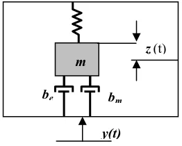
A resonant micro-generator can be modelled as a spring-mass-damper system [5] as shown in Figure 1.
z (t) m
be bm
y(t)
Fig. 1: Generic vibration energy conversion model
When the system with mass, m is excited with a displacement of y(t) relatives to the system housing, a net displacement z(t) is produced and the generic equation derived from the Newton’s second law can be written as,
(
)
() () ())
(t b b zt z t myt z
m&& + e+ m & +
κ
=− && (1)The system is designed to be operated at its resonant frequency, where the maximum output power equation can be simplified as,
(
)
22
max
4 n e m
in eA m P
ζ ζ
ω ζ +
= (2)
The mechanical damping factor is a property of the system which is difficult to control. However, the electrical damping factor can simply be varied by using different resistive load. Once the resistive load is matched with the mechanical damping, maximum energy is transferred from the mechanical to electrical domain.
Fabrication Technique
Lead zirconate titanate (PZT) was used as the functional element of the micro-generator. The PZT was made into piezoceramic (cermet) paste, by mixing with lead borosilicate powder as the permanent binder together with an organic vehicle to make a printable paste [6]. Carbon paste, similar to that described by Birol et al [7] for the purpose of low temperature co-fired ceramic (LTCC) technology, was used as the sacrificial layer and silver/palladium (Ag/Pd) paste was used as the lower and upper electrodes for the composite thick-film cantilever.
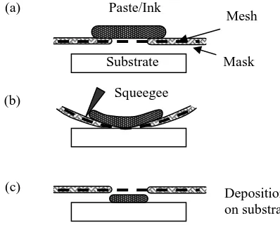
The pastes were printed layer by layer, starting with carbon sacrificial layer on an alumina substrate using thick-film printing screen. The screen was made from a finely woven mesh of stainless steel for optimum accuracy of registration and high resolution printing. The minimum feature is about 100 μm and each layer thickness after co-firing is around 30 μm (depends on mesh of the screen and the viscosity of the paste). The screen printing steps are shown in Fig.2.
Fig. 2: Thick-film screen printing steps
Firstly, the paste is smeared across the pattern on the screen. The screen is adjusted to a gap of between 0.5 mm to 1 mm from the substrate. A squeegee is then
brought into contact with the screen which deflects the screen and the paste is drawn through by surface tension between the ink and substrate. The print is then dried in an infrared dryer before the next layer of film is deposited.
The steps are repeated for printing Ag/Pd paste over the carbon sacrificial layer, as the lower electrode, followed by a few layers of PZT to obtain the desired thickness and finally Ag/Pd paste is again printed on PZT as the upper electrode. The composite films were then co-fired together at a peak temperature of 850 °C, holding for 10 minutes, in a multi-zones furnace. In the co-firing process, the carbon sacrificial layer was burnt off in air and releasing a composite free-standing structure, as shown in Fig. 3b.
Two cantilevers of the same width, 10 mm, but different lengths, 15 mm and 20 mm, were designed (Fig. 3b). Four printed-dried layers of PZT were measured to have a total thickness of 80 μm after co-firing. After fabrication, the free-standing cantilevers were found to have shrunk 10 % from their original dimensions.
Fig. 3: Free-standing cantilever: a) Design layout and b) the prototype
Experimental Procedure
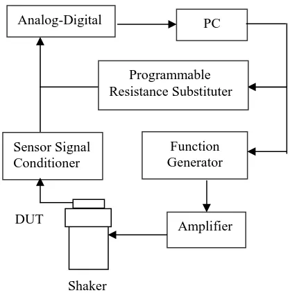
The samples were characterised on a shaker table operated in sinusoidal vibration in a range of different frequencies near to the resonant frequency of the beam. The acceleration level was maintained at a constant level by using a feedback system as shown in Fig. 4. The accelerometer in the shaker measures the actual value of frequency and acceleration level and is fedback into the control processor. A processed signal is then generated and amplified to drive the shaker to produce the desired acceleration level at a given frequency.
The output voltage power from the device is driven into a programmable resistance load and subsequently Paste/Ink
Mesh
Mask Substrate
Squeegee (a)
(b)
(c) Deposition
on substrate
Potential Free-Standing Structure
L0
W0
Solder Pad Sacrificial
Layer
(a)
converted to a digital signal and is measured with National Instrument Sequence Test programme.
Fig. 4: Diagram of sequence test system.
Results and Discussion
A sample of length 18 mm, width 9 mm and piezoelectric thickness of 80 μm was used for the performance evaluation at different acceleration levels. An open circuit output voltage of 130 mV was measured at acceleration level of 0.98 ms-2, but the voltage dropped to about 25 mV when connected to external resistive load of 60 kΩ. A maximum electrical power of 10 nW was produced.
The output power increases with the acceleration level, but the fundamental resonant frequency was found to be shifting to lower frequency as the acceleration increases, as shown in Fig. 5. The power increases by a factor of more than 25 when accelerated at 9.81 ms-2. Non-linearity in the frequency response at different acceleration levels is an undesirable effect for a micro-generator.
When designing a micro-generator to harvest energy from the ambient environment, the acceleration level and the frequency of the vibration source have to be taken into account. Typically, the acceleration levels from environment sources can vary in the range of 0.5 – 10 ms
-2
. Owing to the effect of non-linearity, the generator may not be excited at its exact resonant frequency at different acceleration levels as shown in Fig. 5. Therefore micro-generators have to be designed to operate across a range of frequencies. Fig. 6 shows the performance of micro-generator at different acceleration levels. Micro-generators designed to operate at a resonant frequency of 235 Hz are able to cover a wider range of acceleration levels from as low as 0.1 g (0.981 ms-2). If the vibration
frequency for the source changed to 230 Hz, the micro-generator will not be responded until an acceleration level of 0.5 g is achieved and produce maximum power when an acceleration of 0.8 g is reached.
PC
220 225 230 235 240 245 250
fr (Hz)
Fig. 5: Maximum output power for a cantilever micro-generator with length 18 mm, width 9 mm and piezoceramic thickness of 80 μm, at different acceleration level (1 g = 9.81 ms-2).
Fig. 6: Maximum output power for the micro-generator at different acceleration level and frequency range from 230 Hz to 240 Hz.
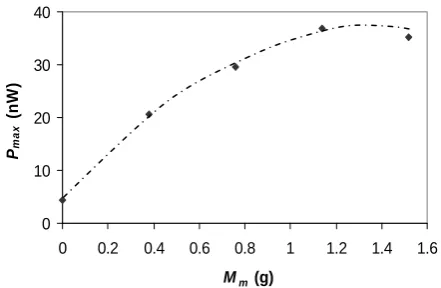
In another experiment, a sample with dimensions of length 13.5 mm, width 9 mm, and thickness 80 μm, was attached to a proof mass with different weights. It was tested with an acceleration level of 0.98 ms-2. The fundamental resonant frequency of the sample with no proof mass attached was measured at 505.5 Hz.
The fundamental resonant frequency of the cantilever was able to be adjusted by adding proof mass. The natural frequency of the samples was able to be reduced below 100 Hz with a proof mass of weight 1.14 g as shown in Fig. 7.
g, resulted in an eight-fold improvement of output power compared to a device with no added proof mass. A further increment of proof mass, however, decreased the output power as shown in Fig.8. This is because, the mechanical damping increases as the mass at the tip of the beam increases dissipating the produced energy and the kinetic energy of the beam is higher.
Fig. 7: Low frequency micro-generator with proof mass attached
Fig. 8: Maximum output power at different additional proof mass when driving resistive load of 60 kΩ, at acceleration level of 0.1 g.
Conclusions
Piezoelectric thick-film free-standing structures in the form of a cantilever, were fabricated with combination of conventional thick-film technology and sacrificial layer techniques. They have been shown to be capable of producing useful amounts of electrical power when driving an optimal value of external resistive load. The power was found to increase at high levels of acceleration, but also suffer from a non-linear effect, which needs to be considered when designing micro-generators for use in environments having random
vibrations. The addition of a poof mass to the cantilever increases the output power and also enables the device to function at reduced levels of vibration.
References
1. White, N.M., Glynne-Jones, P., Beeby, S.P., “A Novel Thick-Film Piezoelectric Micro-Generator,” Smart Mater. Struct., Vol. 10, (2001), pp. 850-852. 2. Torah, R.N., Beeby, S.P., White, N.M., “Experimental
Investigation into The Effect of Substrate Clamping on The Piezoelectric Behaviour of Thick-Film PZT Elements,” J. Phys D, Vol 37, (2004), pp. 1-5.
0 100 200 300 400 500 600
0 0.2 0.4 0.6 0.8 1 1.2 1.4 1.6
Mm(g)
fr
(H
z
) 3. Yalcinkaya, F., Powner, E.T., “Intelligent Structure,”
Sensor Review, Vol. 16, (1996), pp. 32-37.
4. Stecher, G., “Free Supporting Structures in Thick-Film Technology: A Substrate Integrated Pressure Sensor,” Proc 6th European Microelectronics Conf, Bournemouth, 1987, pp. 421-427.
5. Williams, C.B., Yates, R.B., “Analysis of A Micro-electric Generator for Microsystems,” Proc Transducers 95/Eurosensors IX, 1995, pp. 369-372. 6. Torah, R., Beeby, S.P., White, N.M., “An Improved
Thick-Film Piezoelectric Material by Powder blending and Enhanced Processing Parameters,” IEEE Trans. Ultrason., Ferroelectr., and Freq. Control, Vol. 52, No. 1 (2005), pp. 10-16.
7. Birol, H., Maeder, T., Ryser, P., “Fabrication of LTCC Micro-Fluidic Devices Using Sacrificial Carbon Layers,” J. Appl. Ceram. Technol., Vol. 2 (2005), pp. 345-354.
0 10 20 30 40
0 0.2 0.4 0.6 0.8 1 1.2 1.4 1.6
Mm (g)
Pma
x
(n
W