BORANG PENGESAHAN STATUS TESIS*
JUDUL :
SESI PENGAJIAN : _ _ _ _
Saya
mengaku membenarkan tesis Projek Sarjana Muda ini disimpan di Perpustakaan Fakulti Teknologi Maklumat dan Komunikasi dengan syarat-syarat kegunaan seperti berikut:
Tesis dan projekadalah hakmilik Universiti Teknikal Malaysia Melaka.
Perpustakaan Fakulti Teknologi Maklumat dan Komunikasi dibenarkan membuat salinan untuk tujuan pengajian sahaja.
Perpustakaan Fakulti Teknologi Maklumat dan Komunikasi dibenarkan membuat salinan tesis ini sebagai bahan pertukaran antara institusi pengajian tinggi.
** Sila tandakan (/)
SULIT (Mengandungi maklumat yang berdarjah
keselamatan atau kepentingan Malaysiaseperti yang termaktub di dalam AKTA RAHSIA RASMI 1972)
TERHAD (Mengandungi maklumat TERHAD yang telah ditentukan oleh organisasi/badan di mana penyelidikan dijalankan)
TIDAK TERHAD
(TANDATANGAN PENULIS) (TANDATANGAN PENYELIA)
Alamat tetap:
Nama Penyelia
Tarikh: Tarikh:
CATATAN: * Tesis dimaksudkan sebagai Laporan Projek Sarjana Muda (PSM).
** Jika tesis ini SULIT atau atau TERHAD, sila lampirkan surat daripada pihak berkuasa.
2012/2013
MAILBOX NOTIFICATION VIA SMS
MAILBOX NOTIFICATION VIA SMS
MOHD NOR IFTIKHAR BIN MAKHTAR
This report is submitted in partial fulfilment of the requirements for the Bachelor of Computer Science (Computer Networking)
FACULTY OF INFORMATION AND COMMUNICATION TECHNOLOGY UNIVERSITI TEKNIKAL MALAYSIA MELAKA
i
DECLARATION
I hereby declare that this project report entitled
MAILBOX NOTIFICATION VIA SMS
is written by me and is my own effort and that no part has been plagiarized
without citations.
STUDENT : _________________________ Date: _______________
(MOHD NOR IFTIKHAR
BIN MAKHTAR )
SUPERVISOR : _________________________ Date: _______________
(DR NURUL AZMA
DEDICATION
Specially dedicated to my beloved parents, siblings,
friends who have encouraged, guided and inspired me throughout
my journey of education. Besides that, I would like to dedicated
to my supervisor who always have passionate and guided me
iii
ACKNOWLEDGEMENT
First and foremost, I would like to thank to my supervisor of this project,
Dr Nurul Azma Binti Zakaria for the valuable guidance and advice. She inspired
me greatly to work in this project. Her willingness to motivate me contributed
tremendously to my project. I also would like to thank her for showing me some example that related to the topic of my project. Besides, I would like to thank the
authority of Technical Malaysia University (UTeM) for providing me with a
good environment and facilities to complete this project.
Finally, an honourable mention goes to my families and friends for their
understandings and supports on me in completing this project. Without helps of
the particular that mentioned above, I would face many difficulties while doing
this project. Last but not least, thank you once again and may Allah SWT bless
ABSTRACT
Global System for Mobile Communication (GSM) is one of the cellular network
technology that been widely used around the world. GSM includes the short messaging
service (SMS) that enables users to send 160-character text messages to each other.
Short Message Service (SMS) is a text messaging service component of phone, web, or
mobile communication systems, using standardized communications protocols that
allow the exchange of short text messages between fixed line or mobile phone devices.
SMS is been used as a medium for communication in this project because SMS is one of
the fastest and reliable way in transfering information. By integrating the GSM with the
Programmable Interface Controller (PIC), SMS will be generate to inform the user when
there is new mail been delivered. When a new mail is place inside the mailbox, the
system will generate an alert system for the user that is SMS and it is a real-time
notification. This system will ease the user in the aspect of energy and time because of
v
ABSTRAK
Global System for Mobile Communication (GSM) adalah salah satu teknologi
rangkaian yang di pakai secara meluas di seluruh dunia. Short Message Service (SMS)
merupakan antara perkhidmatan yang di tawarkan GSM membolehkan para pengguna
untuk menghantar 160 patah perkataan kepada satu sama lain. SMS adalah komponen
perkhidmatan untuk telefon bimbit, laman sesawang atau sistem telekomunikasi
menggunakan piawaian tetap protocol telekomunikasi yang membenarkan pertukaran
pesanan ringkas antara talian tetap atau peranti telefon bimbit. SMS digunakan sebagai
medium telekomunikasi di dalam projek ini kerana SMS merupakan salah satu cara yang
cepat dan boleh di harapkan dalam menyampaikan maklumat. Dengan penggunaan GSM
dan Programmable Interface Controller (PIC) di gabungkan, SMS akan dihasilkan untuk
memberitahu pengguna apabila surat baru di hantar kepada mereka. SMS yang dihantar
juga merupakan notifikasi masa sebenar. Sistem ini akan memudahkan para pengguna
dari segi aspek tenaga dan masa kerana SMS pemberitahuan yang telah dihantar kepada
LIST OF DIAGRAM
DIAGRAM / FIGURES
TITTLE PAGE
Figure 2.1 Centralized mailbox 7
Figure 2.2 GSM modem 8
Figure 2.3 3GPP Family Technology Evolution 9
Figure 2.4 Limit switch 9
Figure 2.5 PIC16F877A microcontroller 11
Figure 2.6 PIC16F877A microcontroller logical design 12
Figure 3.1 The Waterfall Cycle 16
Figure 4.1 MikroC PRO 22
Figure 4.2 Proteus 7 Professional 23
Figure 4.3 PIC16F877A Microcontroller 23
Figure 4.4 Limit Switch 24
Figure 4.5 GSM Modem 25
Figure 4.6 Voltage regulator 25
Figure 4.7 Breadboard 26
Figure 4.8 Jump wire 27
Figure 4.9 Capacitor 27
Figure 4.10 Resistor 28
Figure 4.11 Diode 29
Figure 4.12 Toggle switch 29
Figure 4.13 Cable RS232 30
Figure 4.14 PCB Board 30
Figure 4.15 Soldering Equipment 31
Figure 4.16 USB ICSP PIC Programmer 31
Figure 4.17 ICSP Programmer Socket 32
Figure 4.19 The overall project planning 34
vii
Figure 4.21 Software Work Flow 37
Figure 4.22 Circuit Design 38
Figure 4.23 Declare Port 38
Figure 4.24 Create Function 38
Figure 4.25 Hold Value 39
Figure 4.26 Information Stored 39
Figure 4.27 AT command program 39
Figure 5.1 Circuit Board 44
Figure 5.2 The LED of Limit Switch 44
Figure 5.3 GSM Modem 45
Figure 5.4 Putty Software 46
Figure 5.5 Change speed value 46
Figure 5.6 Check the condition 47
Figure 5.7 Set SMS text mode 47
Figure 5.8 Send the text message 47
Figure 5.9 Message sent 48
Figure 5.10 Circuit Design 49
Figure 5.11 Selecting the PIC 49
Figure 5.12 Selecting file path 50
Figure 5.13 Selecting the file path 50
Figure 5.14 Insert the coding 51
Figure 5.15 Play button for simulation 51
Figure 5.16 The board switch is on 52
Figure 5.17 Limit switch LED light up 52
Figure 5.18 Limit switch is on 52
Figure 5.19 AT command 53
Figure 5.20 AT command 53
Figure 5.21 Limit switch LED light up 53
Figure 5.22 Limit switch is on 54
Figure 5.23 AT command 54
Figure 5.25 Message sent 1 55
ix
LIST OF TABLES
TABLE TITLE PAGES
TABLE OF CONTENTS
CHAPTER SUBJECT PAGE
DECLARATION i
DEDICATION ii
ACKNOWLEDGEMENTS iii
ABSTRACT iv
ABSTRAK v
LIST OF FIGURES vi
LIST OF TABLES ix
CHAPTER I INTRODUCTION
1.1 Project Background 1
1.2 Problem Statements 2
1.3 Objective 2
1.4 Scope 2
1.5 Expected Output 3
1.6 Report Organization 3
CHAPTER II LITERATURE REVIEW
2.1 Introduction 6
2.2 Fact and Findings 6
2.2.1 Mailing System 6
2.2.2 Global System For Mobile Communication (GSM)
7
2.2.3 Limit Switch Sensor 9
2.2.4 Programmable Interface
Controllers (PIC)
10
2.3 Related Work/Previous Work 12
2.3.1 A remote Home Security System
Based on Wireless Sensor
Network and GSM Technology
12
2.3.2 Low Cost Flood Alert via SMS 13
2.3.3 Security System Alert via SMS 13
2.4 Analysis Of Current Problem 14
2.5 Conclusion 14
CHAPTER III METHODOLOGY
3.1 Introduction 15
3.2 Categories analysis 15
3.2.1 Test Bed 15
3.3 Steps or Stages Involved 16
3.3.1 PHASE 1: Requirements 17
3.3.2 PHASE 2: Design
3.3.2 PHASE 3: Implementation
3.3.2 PHASE 4: Testing
3.3.2 PHASE 5: Documentation
17
17
17
18
3.4 Milestones For PSM
3.6 Conclusion 19
CHAPTER IV DESIGN AND IMPLEMENTATION
4.1 Introduction 21
4.2 Project Requirement 22
4.2.1 Software Requirement 22
4.2.2 Hardware Requirement 23
4.3 Project Planning
4.4 Project Block Diagram
4.5 Project Description
4.5.1 Hardware Development
4.5.2 Software Development
4.5.1 Circuit Design
33 35 35 36 37 37
4.6 Coding Algorithm
4.7 Conclusion
38
40
CHAPTER V TESTING
5.1 Introduction 41
5.2 Test Plan 41
5.3 Test Organization 42
5.4 Test Strategy 42
5.5 Classes of Test
5.5.1 Simulation Testing
5.5.2 Hardware Testing
5.6 Project Hardware
5.6.1 Project Circuit Board
5.6.2 GSM Modem
5.7 Test Result
5.7.1 GSM Modem
5.7.2 System testing
CHAPTER VI CONCLUSION
6.1 Introduction 57
6.2 Limitations 57
6.3 Project Strengths 58
6.4 Project Weaknesses 58
6.5 Contribution 59
6.6 Prepositions for Improvement 59
CHAPTER I
INTRODUCTION
1.1 Project Background
Nowadays, the technologies grown very fast and rapidly in this world.
Eventhoughthe technologies era are growing rapidly, one of the system that
still been used in this era is mailing system. Mailing system still been used
because it is still convenient and one of the effective way to give information
to the user. The problem is the user need to check their mailbox periodically
to check either they receive the letter or not. Most of the users are very
slothful to check their mailbox especially those who live in multi-story
building such as the apartment, condominium and office. It is because of their
mailing system is centralized to one location of the building.
This will lead to overlooked if any important or confidential letter are
been delivered that need to be view as soon as possible by the user. The user
are expecting if there any way or solution that will overcome this problem.
Due to modern technologies, there is a way to connect Global System for
Mobile Communication (GSM) modem with a programmable interface
controllers equip with limit switch sensor that will notify the user for the
incoming letter. The system will give an alert to the user that is Short
Message System (SMS). This system will help the user to notify them with a
2
1.2 Problem Statement
The problem is the user need to check their mailbox periodically to
check either they receive the letter or not. Most of the users are very slothful
to check their mailbox especially those who live in multi-story building such
as the apartment, condominium and office. This will lead to overlooked if any
important or confidential letter are been delivered that need to be view as
soon as possible by the user. The user also will waste their time and enrgy to
check for the mail if there is no new mail delivered to their mailbox. The user
are expecting if there any way or solution that will overcome this problem.
1.3 Objective
The objective of this project are :
1. To conduct in-depth study of system involves limit switch sensor and
GSM modem with Programmable Interface Controller (PIC)
2. To design a prototype that will detect the incoming letter and notify
the user
3. To improve the mechanism for incoming letter notification
1.4 Scope
The scope of this project is to design a system that using limit switch
sensor and a GSM modem that can be integrate to notify the user when a
letter sent to the mailbox. This project will introduce a system that will
replace the method of checking the user mailbox by giving notification to the
user with a Short Message Service (SMS). The project also will make us
sensor, GSM modem and the programmable interface controllers with the
application that will be study and used during this project.
This system is develop to ease daily life of the user especially for the
users that live in multi-story building such as at the apartment or
condominium. This system will give benefit to them in term of saving their
energy and time. It will also help them from overlooked any important or
confidential letter.
1.5 Expected Output
The expected output of this project is the mailbox alert system will
help the user from overlooked if any important or confidential letter are been
delivered to them. The SMS that will be sent from the system as the alert for
the user will ensure that they will get notify within the real-time they receive
the letter. This system will also benefit the user in the aspect of energy and
time because of the alert that they received sent to their mobile phone.
1.6 Report Organization
Upon completing this project, there will be six chapter for the purpose
of documentation that will briefly explain all the process and the flow for completing this project. The purpose of dividing the report into several
chapter is to ease the person that want to review this project for future review.
Chapter 1 discuss about the general view for the project including the
project background and the objective/goals that need to be achieved. The
problem statement is also stated in this chapter to show the purpose of
developing the project. Report organization is to define what will be defined
4
Chapter 2 consist of the research for literature review of the project
and related/previous work that have the same scope or similarities with this
project. Analysis of current problems are also included to identify what is the
drawbacks that the developer faced and proposed further solution for the
project. Last but not least, the conclusion of this chapter will be included to
complete this chapter.
Chapter 3 consist of the project methodology model that has been
choose for the project that System Development Life Cycle (SDLC). The
milestones for the subject are also included to ensure that the developer have
a schedule or good time management to complete the project. This project
uses the test bed concept for the system development process. Last but not
least, the conclusion of this chapter will be included to complete this chapter.
Chapter 4 consist of the design and implementation that will be use for
this project. The hardware and software requirements also included to make
sure the component or hardware that been used are defined correctly.
Implementation describes the details on how it works or carried out and
samples of result or output. Last but not least, the conclusion of this chapter
will be included to complete this chapter.
Chapter 5 consist of testing and analysis describing where it includes
the method or step how to test and analyze the system or product that has
been developed. To complete this chapter, conclusion will also included.
After gone through all the process and successfully achieved all the
objectives as stated in the earlier chapter, the overall project can be conclude
as explain inChapter 6. Chapter 6 consist of limitations, contribution and
1.7 Conclusion
At the end of this project, this project will help the user to check their
mailbox without taking so much time and conserve their energy too. This
project is design especially for the user that live in a multi-story building but
for a conventional home also still can use the system. This project will be
helpful for them and changing their method to check their mailbox because
they will receive a notification via SMS if there any letter detected in their
mailbox. This project also help us in learning the concept of the system that
use the electronic parts such as limit switch sensor and a PIC with help by the
GSM modem to generate the notification for the user. In the next chapter, the
literature review about the project are discussed and collecting information of
6
CHAPTER II
LITERATURE REVIEW
2.1 Introduction
In this chapter, the developer will doing some research about the
method or application to gain the information regarding the project. Any
journals or documents that are related to this project are being review to make
as the references for the project.
2.2 Fact And Findings
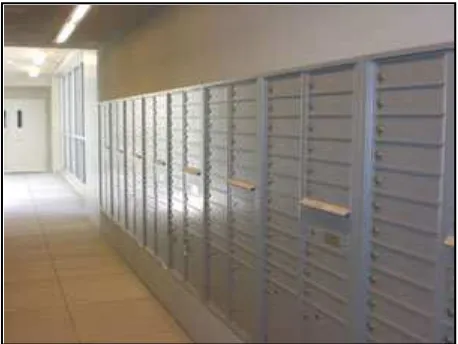
2.2.1 Mailing System
Mailing system is used to transport letters and objects for examples
written documents, typically enclosed in envelopes, and also small packages.
The transportation path originating from sender to the recipient has become a
sophisticated network of carriers ranging from people, to airplanes, to tractor
trailers, to smaller vehicles [1]. Objects sent through the postal system is
called mail or post. This system is being used until the latest system which is
an electronic mailing system takeover. But, mail is still being used as a
medium to send an important information or document. Usually mailing
information consists of a destination address and a postage stamp. The figure
Figure 2.1 Centralized mailbox
2.2.2 Global System For Mobile Communication (GSM)
A technology that starts from Europe and then spread out in every
nook and cranny of the world. GSM is a digital cellular phone technology
based on TDMA. It was developed to replace the first generation (1G) of
analog cellular networks. The GSM was build using digital technology and
uses narrowband Time Division Multiple Access (TDMA) technique to
transmit signals which originally described a digital, circuit switched network
optimized for full duplex voice telephony. It has an ability to carry 64 kbps to
120 Mbps of data rates. Over 200 GSM networks (including DCS1800 and PCS1900) are operational in 110 countries around the world. In the beginning
of 1994, there were 1.3 million subscribers worldwide [2].
Other than that, the GSM provides Roaming service which is used to
advanced voice and data services. Roaming is where you can use your GSM
phone number in another GSM network that will operates at either 900 MHz
or 1,800 MHz frequency band. GSM phones use a Subscriber Identity
Module (SIM) smart card which contains all of the user account information.
8
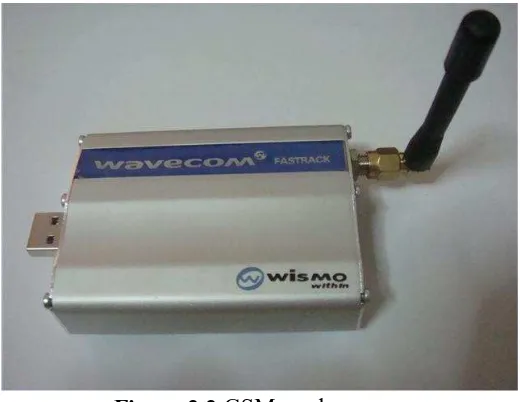
send text messages to each other. Figure 2.2 below show one of the GSM
modem type that been used nowadays.
Figure 2.2 GSM modem
A GSM modem works just like a mobile phone. It is a modem which accepts
a SIM card, and subscribe to a mobile operator. Thus, from the mobile
operator’s point of view, a GSM modem looks just like a mobile phone.
Besides, there is certain mobile phone that provides GSM modem
capabilities. Figure 2.3 shows the evolution of 3GPP family.There are several
reasons why GSM is so popular among operators and their customers:
1. Clear voice quality, as an alternative to wire line telephony for users.
2. Spectral flexibility, numerous spectrum bands is available for user devices and has an infrastructure network.
3. Tight security, prevention from eavesdropping and hacking.
Figure 2.3 GPP Family Technology Evolution
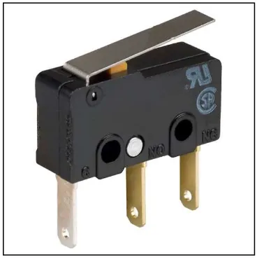
2.2.3 Limit Switch Sensor
A limit switch is a switch works by the movement of a machine part
and existence or presence of an object. It is usually used for controlling
machine, to count objects passing a point, or as safety interlocks. It is an
electromechanical device which consists of an actuator that was linked to a
set of contacts. When an object touches the actuator, the device will operates
the contacts to start or stop an electrical connection. Figure 2.4 below show a
limit switch hardware.