KINEMATIC SYNTHESIS OF PLANAR, SHAPE-CHANGING RIGID
BODY MECHANISMS FOR DESIGN PROFILES WITH SIGNIFICANT
DIFFERENCES IN ARC LENGTH
Dissertation
Submitted to
The School of Engineering of the
UNIVERSITY OF DAYTON
In Partial Fulfillment of the Requirements for
The Degree of
Doctor of Philosophy in Mechanical Engineering
By
Shamsul Anuar Shamsudin
Dayton, Ohio
KINEMATIC SYNTHESIS OF PLANAR, SHAPE-CHANGING RIGID BODY MECHANISMS
FOR DESIGN PROFILES WITH SIGNIFICANT DIFFERENCES IN ARC LENGTH
Name: Shamsudin, Shamsul Anuar
APPROVED BY:
Andrew P. Murray, Ph.D. Advisor Committee Chairman Professor, Dept. of Mechanical and Aerospace Engineering
Vinod K. Jain, Ph.D. Committee Member
Professor, Dept. of Mechanical and Aerospace Engineering
David H. Myszka, Ph.D., P.E. Committee Member
Associate Professor, Dept. of
Mechanical and Aerospace Engineering
James P. Schmiedeler, Ph.D. Committee Member
Associate Professor, Dept. of Aerospace and Mechanical Engineering, University of Notre Dame
John G. Weber, Ph.D. Associate Dean School of Engineering
c
Copyright by Shamsul Anuar Shamsudin
All rights reserved
ABSTRACT
KINEMATIC SYNTHESIS OF PLANAR, SHAPE-CHANGING RIGID BODY MECHANISMS
FOR DESIGN PROFILES WITH SIGNIFICANT DIFFERENCES IN ARC LENGTH
Name: Shamsudin, Shamsul Anuar University of Dayton
Advisor: Dr. Andrew P. Murray
Design of shape-changing machinery is an area of growing significance. Shape-change may be
employed in the near future to vary the cross section of a wing, create flow-field control by altering
shapes to locally affect downstream fluid behavior, or vary the size of a car seat to meet a wider
array of ergonomic needs. Rigid body shape-change mechanisms offer many advantages including
the high capacity to endure substantial loads while achieving large displacements. Their design
techniques are also well-established. The goal of this research project is to develop the synthesis
theory to address planar rigid-body shape-change where significant differences in arc length define
the problem.
This dissertation presents a process to approximate several design profiles of significantly
differ-ent arc lengths with rigid bodies connected by revolute and prismatic joints. This process is referred
to as segmentation, and the initial step is the conversion of the design profiles into piecewise linear
This is followed by segmentation which serves to identify the contiguous sets of pieces that
are best approximated by either a rigid bodyM-segment or a constant curvature C-segment that contains a prismatic joint.
To facilitate segmentation, the concept of segment matrix is introduced. A segment matrix
identifies the lengths of the bodies in the sequence of M- andC-segments along a profile. The segmentation process is applied to open, closed, and fixed-end design profiles. A
M
ATLAB-basedtool was developed to facilitate visual assessment of the process and results. Finally, this dissertation
illustrates five mechanization examples that apply the segmentation process, and the fundamental
mechanism synthesis to guide the motion of the chain of rigid bodies to progress to the subsequent
To my parents, Halimah and Shamsudin,
ACKNOWLEDGMENTS
Graduate studies at the University of Dayton have been both fun and challenging. The classes
have broadened my perspective as a mechanical engineering graduate, and provided me with the
skills and knowledge needed to become an accomplished engineering instructor, advisor, and
re-searcher. I also found the research group meetings where we shared updates, carried out small
projects, and learned from each other, very beneficial. This interaction has contributed in many
ways to the successful completion of this dissertation which represents the most important
mile-stone on my road to graduation.
I would like to thank Professor Andrew Murray for his guidance, and also his patience during
the extended period that I took to complete this journey. When obstacles came my way, he was
always available with solutions to see me through. Many of my friends are of the opinion that I am
fortunate to have him as my advisor, and I could not agree more.
I am also grateful to the other committee members for their invaluable contribution towards
this research. Professor Vinod Jain guided me in his class and encouraged me to complete my
studies. I thank Professor David Myszka for being supportive in the group meetings and for being
instrumental in the writing of the technical papers we worked on. I also wish to thank Professor
James Schmiedeler for his involvement in my doctoral research work and publications.
I would like to express my appreciation for the ever so generous financial support I received from
I look forward to serving the country as an educator and sharing the knowledge of machine theory
with the future generations of mechanical engineers.
I am grateful to fellow researchers at the Design of Innovative Machines Laboratory (DIMLab):
Jonathan Lauden, Ali AlMandeel, ‘Chef’ Lin Li, Tong YuXuan, Jo Binjue Li, Dr. Dave A. Perkins,
Andrew Hazlett, Brandon Leedy, Joshua Nieman, Sarotham Reddy and Linda Leben for keeping
me company at the lab and sharing their ideas. I thank Kai Zhao of the University of Notre Dame
for his help in the mechanization issues. I am also indebted to Dr. Aaron Altman and Dr. Markus
P. Rumpfkeil for their insights on aircraft wings. I am grateful to Rise’ Kreitzer, Capt. Edward
Seaman, Constance Norman, Dr. Nicoletta Hary, and all the staff at the Roesch and Marian Library
where I was engaged on a part-time basis.
My family has played a major role in this endeavor and I would like to thank my wife Asmida
and my children Nurul Adlina, Khairul Amri, and Ahmad Syakir for their love, support, and
un-derstanding. I am forever indebted to them all. I am also aware that my parents, Halimah and
Shamsudin, constantly include me in their prayers, and it is my hope that this achievement brings
them much joy.
Lastly, but most importantly, I thank The Almighty God for His countless blessings, and for
pro-viding me with the determination to complete my studies and achieve my goal. With this
achieve-ment I pray for the ability to harness my expertise in this field for the education of future
TABLE OF CONTENTS
Page
ABSTRACT . . . iii
DEDICATION . . . v
ACKNOWLEDGMENTS . . . vi
TABLE OF CONTENTS . . . viii
LIST OF FIGURES . . . xi
LIST OF TABLES . . . xviii
NOMENCLATURE . . . xx
CHAPTERS: I. INTRODUCTION . . . 1
1.1 State of the Art in Shape-Change . . . 1
1.1.1 Airfoils and Blades . . . 1
1.1.2 Ship and Boat Hulls . . . 5
1.1.3 Antenna and Mirror . . . 5
1.1.4 Convertible Structures . . . 6
1.1.5 Robotic Gripper and Prosthetics . . . 8
1.1.6 Artwork . . . 8
1.2 Various Shape-Changing Methods . . . 9
1.2.1 Rigid-Body Shape-Change . . . 9
1.2.2 Compliant Mechanisms . . . 12
1.2.3 Membranes and Smart Materials . . . 13
1.2.4 Combinations Involving Membranes and Rigid Bodies . . . 14
1.3 Rigid-Body, Shape-Changing, Mechanism Design Methodology . . . 14
1.3.1 Profiles and Segmentation . . . 15
1.3.2 Mechanization Methods . . . 16
1.4 Shape-Changing for Different Arc-Length Profiles . . . 19
1.4.1 Different Arc Length Examples . . . 19
1.4.2 New Profile Generation . . . 23
1.4.3 New Segmentation Method . . . 24
1.5 Organization . . . 25
II. OPERATIONS ON TARGET PROFILES . . . 26
2.1 Target Profile Generation . . . 26
2.2 Metrics on Target Profiles . . . 31
2.2.1 The Closed-Form Similarity Transformation Solution . . . 36
2.2.2 Example . . . 39
2.3 Curvature Calculations . . . 41
2.3.1 Calculating the Curvature of Target Profiles . . . 41
2.3.2 Curvature Smoothing . . . 42
2.3.3 Regenerating the Target Profile . . . 43
III. THE SEGMENTATION PROCESS . . . 48
3.1 A New Segmentation Process for Target Profiles of Different Arc Lengths . . . . 48
3.1.1 The Segment Matrix . . . 50
3.1.2 M-Segments . . . . 51
3.1.3 C-Segments . . . . 52
3.2 Evaluating and Adjusting the Segment Matrix . . . 54
3.3 Joining the Chain . . . 58
3.4 Compound Segment Types . . . 61
3.5 Other Profile Examples . . . 63
3.5.1 Closed-Profile Example . . . 63
3.5.2 Fixed-End Profile Examples . . . 63
3.6 Comparing the Number of Joints . . . 65
3.7 Versatility of the Segmentation Method . . . 66
3.8 Automating the Segmentation Process . . . 68
IV. SOFTWARE IMPLEMENTATION . . . 72
4.1 Design Profiles . . . 72
4.2 Target Profiles . . . 73
4.3 Segmentation . . . 75
4.4 Visualization of Segmentation Results . . . 77
4.5 Compound Segments . . . 77
5.1.1 Car Seat . . . 80
5.1.2 U-to-D Transformation . . . 85
5.2 Fixed-End Example . . . 89
5.3 Closed-Loop Example . . . 96
5.3.1 Morphing Wing . . . 96
5.3.2 Flow-Field Control . . . 96
VI. CONCLUSIONS AND FUTURE WORK . . . 106
6.1 Contributions . . . 106
6.2 Future Work . . . 109
BIBLIOGRAPHY . . . 114
APPENDICES: A.
M
ATLAB IMPLEMENTATION OF THE SEGMENTATION PROCESS . . . 123A-1 Generating Design Profiles . . . 123
A-1.1 Editing Design Profiles . . . 127
A-2 Generating Target Profiles . . . 136
LIST OF FIGURES
Figure Page
1 An early concept of a compliant mechanism for a morphing wing slat and flap de-signed for the F-111 fighter aircraft [5]. . . 2
2 A morphing wing provides only the amount of lift necessary, reducing the fuel use of the aircraft [3]. . . 3
3 A shape-changing spoiler can be used to improve vehicle stability by providing additional downward force when navigating corners. . . 3
4 The control surfaces in a submarine include (a) the starboard (tail) and (b) aft (front) hydroplanes of (c) the HMS Astute [28]. . . 4
5 An underwater stabilizer uses two SMA actuators to move its flap. (a) The trailing edge is in a neutral position. (b) Joule heating causes the trailing edge to deflect up-ward. (c) Cooling of the top actuator returns the trailing edge to its neutral position [29]. . . 5
6 The shape-changing antenna can alter its shape during the scanning and focusing of a wave [33]. . . 6
7 A soft-top convertible roof [40]. . . 7
8 A mobile stage and roof system in (a) stowed and (b), (c), and (d) are alternate deployed configurations [14, 41]. . . 7
9 A compliant mechanism holding a round object [45]. . . 8
11 The mechanism is capable of moving the chain from approximating the “U” to the
“D” as it progresses from (a) through (d) based on work in [46]. . . 10
12 The “skin” or outer layer of the shape-changing machine does not have to be rigid. The GINA has the skeleton mechanism underneath made of rigid members [73]. . . 15
13 A cable extends the length of the prosthetic finger and acts as an actuator [83]. . . . 17
14 (a) A mean segment generated for points 1-2-3 of the two different length profiles. (b) Mapping the mean segments on the profiles does not show good results. . . 18
15 A conventional theoretical pressure distributionCpplot of a four-element wing. The leading-edge and trailing-edge flaps are in deployed positions. . . 19
16 The various types of hulls for ships and boats. . . 20
17 Different cross-sectional shapes along a modern ship’s hull [26]. . . 20
18 The Ti-Ni wires return to its original antenna shape by heating [66]. . . 21
19 (a) Schematic diagram of the multiple dies extrusion system. (b) The frame is axi-ally twisted, and the width of the cross section varies steadily [87]. . . 22
20 (a) Schematic diagram of the multiple dies pultrusion system. (b) The cross-sectional shapes vary gradually [88]. . . 22
21 (a) Various cross-section shapes for the two extruded products. (b) The shape-changing die concept [89]. . . 23
22 Profile types include (a) open profiles, (b) closed profiles, and (c) fixed-end profiles. 27 23 Computation time decreases exponentially assdincreases in size. . . 29
24 Design profile (solid) with an approximating target profile (dashed) where points are positioned to give a constant arc length along the design profile. . . 30
26 (a) Three target profiles, with one deemed the reference profile. (b) Two profiles are transformed to the reference by a similarity transformation (with b = 1). (c) The mean profile. (d) The mean profile transformed back to the original profile locations [46]. . . 33
27 (a) Rigid bodies connected with revolute joints form a chain to closely approximate the profiles. (b) A mechanism design that moves the chain of rigid bodies between the three profiles. . . 34
28 (a) The reference pointsZ1i. (b) The pointszji to undergo the similarity
transfor-mation. (c) The scaled, rotated and translated z2i that align with the Z1i for the optimalb= 0.72,θ =−33.69◦, anddj = [−0.80,0.40]T. (d) The scaled, rotated and translatedz2i that align withZ1iforb= 1. . . 40
29 Target profiles (a) with calculated curvature (b) and smoothed curvature (c). The dashed curves in (a) are regenerated profiles and are nearly identical to the original profiles. . . 44
30 The location of˜zji+1is reconstructed from˜zji−1,˜zji,
˜
αji,βj˜i
andrj˜i. . . 46
31 (a) The first segment from three target profiles to be represented by one mean seg-ment. (b) Segments 2 and 3 shifted to reference segment 1 in a distance minimizing transformation. (c) The mean segment is generated as the average of the correspond-ing segment points. (d) The mean segment is shifted back to the original segments in another distance minimizing transformation. . . 52
32 AC-segment is built and then transformed to its location in a distance minimizing configuration. . . 53
33 (a) The second segment from three target profiles approximated with aC-segment. (b) An arc of the same radius, but varying length, approximates the segment on all profiles. . . 54
34 A rigid-body chain that approximates the target profiles. The chain after the ini-tial segmentation matrix is shown in (a) with Emax = 1.50. The chain after the error-reducing iterations is shown (b) withEmax = 0.38. The inset illustrates that segmentation points are not coincident. . . 57
36 The joining process unites segmentation points, yet changes the error fromEmax = 0.38toEmax = 0.39. . . 60
37 (a) The original chain consisted of 4 segments resulting inEmax = 0.39, yet one revolute joint exhibited limited motion. (b) The2nd and3rdsegments were fused into a compound segment, resulting in a three-segment chain withEmax= 0.45. . 62
38 (a) The E420 and E850 profiles of airfoils. (b) The chain of ten segments with Emax = 0.015. (c) Fusing segments raises the error toEmax= 0.017while reduc-ing the number of joints. . . 64
39 Fixed-end profiles shown in (a). The final, rigid-body, shape-approximating chain is shown in (b) havingEmax= 0.18. . . 65
40 (a) The [M C M M M] chain is selected with an after-assembly error ofEmax =
0.26. (b) A compound segment increases maximum error toEmax = 0.28, which is still lower than the [M C M M] design withEmax= 0.37in (c). . . . 67
41 (a) The design profiles. (b) The [C C M C C M M C C C M C C M C] segmentation withEmax = 0.24. . . 69
42 The range from 0 to 0.2 is an acceptable range to be approximated by an arc of constant curvature. . . 70
43 In order to identify a potential region in which to insert another prismatic joint, the curvature distribution (from Fig. 42) is replotted starting with the end of the previously selected curvature band. . . 71
44 (a) A design profile and its corresponding target profile created with 10 points. (b) The plot of the target profile’s arc length as a function of its number of points. . . 74
45 (a) The silhouettes of a small, an average and a large driver [112]. (b) Seat design profiles that ideally suit the small, average and large drivers from (a). . . 81
46 The three seat profiles can be approximated by the five segment shape-approximating chain in (a). The creation of a compound segment reduces the chain to three seg-ments in (b) with only a visually-acceptable increase in error. . . 82
47 (a) The seat accommodates the1st percentile group, (b) the50th percentile group, and (c) the99thpercentile group. . . 83
49 (a) The same arc length design profiles for U and D. (b) The new profiles include an enlarged “D” so that its overall size is comparable to that of “U.” . . . 86
50 Segmentation shows good approximations with a maximum point-to-point error Emax = 0.27. . . 87
51 (a) The mechanism aligned with the “U.” (b) An interim position close to the “U.” (c) An interim position close to the “D.” (d) The mechanism aligned with the “D.” . 87
52 Labels for the dyads and revolute joints for the UD example. . . 88
53 (a) The NASA 30P30N wing is shown with its slat in the stowed configuration. (b) The slat in the deployed configuration. (c) The slat locations have been used to identify a fixed-end design challenge. . . 90
54 The two rack and pinion systems drive the slat out of the main wing [114]. . . 91
55 (a) Fluctuating instantaneous sound pressure field [115]. (b) Many early types of slats are hinged to the main wing element [116]. . . 92
56 (a) The target profiles generated withsd= 0.1. (b) The four-segment design has an Emax = 0.14. (c) The error minimizing segmentation result with a [C M C] chain andEmax= 0.16. . . 92
57 (a) A fully stowed slat. (b) The slat starts to deploy. (c) An interim position as it approaches the deployed position. (d) The fully deployed (extended) slat. . . 94
58 Labels for the dyads and revolute joints for the wing slat example. . . 95
59 (a) Thin E850 high-speed airfoil and thick E420 high-lift airfoil. (b)-(f) Progression of the morphing wing between E420 and E850 airfoils. The two straight blue lines at the tail are paths for two sliders that guide theC-segment. The curved sliders in red follow a curved path as it guides the other end of theC-segment. . . . 98
60 Labels for the dyads and revolute joints for the morphing airfoil example. . . 98
61 (a) The three profiles of the original flow field example. (b) The new profiles have significant differences in arc lengths. . . 100
63 (a) The mechanism aligned with the ellipse. (b) An interim position between the ellipse and the tear-drop. (c) The mechanism aligned with the tear-drop. (d) An interim position between the tear-drop and the circle. (e) The mechanism aligned with the circle. . . 103
64 (a) A slider and a slot that can be entrenched in the floor or frame. (b) A telescoping element that can operate from inside the device for flow-field control [118]. . . 104
65 Labels for the dyads and revolute joints for the flow-field example. . . 105
66 (a) The mechanization challenges posed by (a) and (b) are significantly different. Associating the identified point as being at the same location in the segmentation in (c) may be an accurate way of approximating bodies, but poses a significant mechanization challenge. . . 110
67 Initial results for a compliant mechanism with living hinges, approximating three profiles. . . 113
A-1 The first two windows in ShapeChanger. . . 124
A-2 (a) The first design profile is sketched. (b) Identifying that another profile is to be added. (c) The second design profile is sketched. (d) Proceed to the editing of the design profiles. . . 126
A-3 (a) A closed design profile is generated in the workspace with left mouse clicks. (b) A right click closes and finishes the profile. . . 127
A-4 (a) A fixed-end design profile is generated in the workspace with left mouse clicks. The second control point of the next profile is clicked. (b) The second profile adopts the same initial point as the first profile, and the connection to it is automatic. (c) The second profile adopts the same final point as the first profile, and the connection to it is automatic with the right click indicating completion of the profile. . . 128
A-5 Editing operations on the design profiles. . . 129
A-6 (a) A click selects and highlights that profile. A second click indicates that point is to be moved. (b) The curve after a new location is selected for the point. . . 130
A-8 (a) A click selects and highlights the profile. A second click indicates the range marked by two magenta squares. (b) If the range is right, select the exact location of the new point. Then the new point appears on the profile after the selection. . . . 132
A-9 (a) Select the curve and then the reference point (b) Click on the new location for the selected reference point on the profile to move the entire profile. . . 133
A-10 (a) The top profile is selected, and a second click indicates the control point about which to rotate. A dialog box opens to input the angle of rotation. (b) The curve after a rotation about the selected control point. . . 135
A-11 (a) A pair of profiles is (b) rescaled to have the same arc length. . . 135
A-12 The workspace presents the two target profiles matching well the design profiles beneath them. . . 136
A-13 The relevant information about target profiles influence the next phase, the segmen-tation. . . 137
A-14 A selection of desired piece length,sd = 4, that leads to a poor match between the design and target profiles. . . 138
A-15 Segmentation process takes the input from this window. . . 141
A-16 (a) Reset starting points dialog box. (b) Original starting points of the design pro-files. (c) New starting points for the target propro-files. . . 142
A-17 (a) A user can set whether to see the optimization process changing the segments’ lengths, or (b) to see the result of each chain design, or just see the final result. . . . 143
A-18 A result from the segment synthesis that is selected due to it having the lowest maximum point-to-point error,Emax= 0.09. . . 144
LIST OF TABLES
Table Page
1 Design vector errors for all five-jointed chains. . . 66
2 Target profile data for the “UDAYTON” example shown in Fig. 41 . . . 68
3 Control points used in constructing the car seat profiles. . . 81
4 The mechanism’s revolute joints for the car seat example in the configuration shown in Fig. 48. . . 84
5 The revolute joints in the segmented chain for the car seat example in the configu-ration shown in Fig. 48. . . 84
6 Control points used in constructing the U and D profiles. . . 85
7 The mechanism’s revolute joints for the UD example in the configuration shown in Fig. 52. . . 88
8 The revolute joints in the segmented chain for the UD example in the configuration shown in Fig. 52. . . 89
9 Control points that define the stowed and deployed profiles of the wing slat. . . 93
10 The revolute joints in the segmented chain for the wing slat example in the config-uration shown in Fig. 58. . . 95
12 The mechanism’s revolute joints for the morphing wing example in the configura-tion shown in Fig. 60. . . 97
13 Mechanism points for the morphing airfoil example in the configuration shown in Fig. 60. . . 99
14 Revolute joints for the morphing airfoil example in the configuration shown in Fig. 60. 99
15 Points used in constructing the circle, ellipse, and tear drop profiles. . . 101
16 The mechanism’s revolute joints for the flow-field example in the configuration shown in Fig. 65. . . 105
NOMENCLATURE
M Mean segment type
C Constant curvature segment type cji Length of pieceion design profilej
Cj Arc length of design profilej sji Length of pieceion target profilej
sd Desired piece length for target profiles N Number of points for a segment
n Number of points for a profile in general mj Number of pieces on target profilej nj Number of points on target profilej
mej Number of pieces forethsegment on profilej nej Number of points forethsegment on profilej
ǫsj Error representing the difference between the average segment length
and the desired piece length
m∗j Number of pieces on target profilejthat minimizesǫsj
n∗j Number of points on target profilejthat minimizesǫsj
Sj Arc length of target profilej
¯
Z1i A set ofipoints on a reference profile
zji A set ofipoints on profilejthat will be transformed Z1t A vector composed ofZ1xt=
X
Z1xi andZ1yt=
X
Z1yifori= 1, . . . , N
zjt A vector composed ofzj xt= X
zj xiandzj yt=Xzj yifori= 1, . . . , N b Scale factor in the similarity transformation
θ Angle of rotation in the similarity transformation
Aj Rotation matrix in the similarity transformation
dj Translation vector in the similarity transformation
D The average squared point deviation between a profile or
a segment with its reference
κji Curvature of pointion target profilej
{αji, βji}
T
The center of a circle passing throughzji−1,
zji andzji+1
rji Radius of curvature of pointion target profilej
φ Angle∠zji−1zjizji+1
MAV A micro unmanned aerial vehicle
SMA Shape-memory alloy
SME Shape-memory effect
DOF Degree(s) of freedom for a mechanism
V A design vector that shows the sequence ofM- andC-segments
SM A segment matrix
Pji−1 A direction vector that extends fromzji−1 tozji ˜
zji A regenerated profile point based on radius of smoothed curvature
and uniform pieces
˜
rji Radius of smoothed curvature of pointion target profilej ˜
κji Smoothed curvature of pointion target profilej n
˜
αji,βj˜i oT
The circle center for finding˜zji+1
p Number of design profiles
q Number of segments in a chain of rigid bodies α Minimum number of pieces per segment
¯
re Mean radius for theethC-segments δ Step angle in constructing aC-segment Eje Error calculated forethsegment on profilej
¯
CHAPTER I
INTRODUCTION
1.1 State of the Art in Shape-Change
Machines can benefit from the capacity to vary between specific shapes in a controlled manner.
Although there are numerous examples of conventional machines that exhibit shape-change, novel
approaches are currently being developed to solve increasingly sophisticated problems and address
a variety of new applications. This chapter presents an overview of this research work and places
the new research generated in this dissertation in its context.
1.1.1 Airfoils and Blades
The focus of much study has been on shape morphing aircraft wings that increase performance
over a range of flight conditions [1, 2]. Most of the design work has centered on changes between
wing profiles of similar arc length [3, 4, 5]. The fundamentals of aerodynamics dictate, however,
that lift and drag can be significantly altered with a change in camber and chord [6]. That is, for
high lift situations (e.g., approach, landing, and climb), a higher camber and longer absolute chord
are desirable, whereas for efficient cruising, a lower camber and shorter chord are desirable. Kota
et al. [5] discovered an early shape-changing mechanism design using rigid-links and fiberglass
superior aerodynamic benefits, as shown in Fig. 1. However, in that work, no significant change in
arc length of the airfoil was considered.
Figure 1: An early concept of a compliant mechanism for a morphing wing slat and flap designed for the F-111 fighter aircraft [5].
Abdulrahim et al. [7] studied a membrane wing for a micro unmanned aerial vehicle (MAV).
The under cambered membrane wing has a wingspan of 24 inches. Such a wing changes its shape by
morphing its entire profile by wire control rods connected to small motors in the fuselage. Limaye et
al. [8] incorporated compliant kits of beams and connectors to model the trailing edge of a morphing
aircraft wing. The compliant beams are deformed to alter the shape of the wing. Strelec and
Lagoudas [9] used smart materials to control the shape of a reconfigurable wing to match a set
of desired airfoil profiles. Weisshaar et al. [10, 11] underscored the importance of searching for new
technologies to gain improved control surfaces for military aircrafts. They used smart materials to
actuate the shape change in the trailing-edge flap of an aircraft wing. Kota et al. [5, 12] and Santer
et al. [13] used compliant mechanisms to change the shape of a control surface that approximates
an airfoil. Kota et al. [12] reported an increase in lift while maintaining a nearly constant drag
coefficient. Another shape-changing wing design is illustrated in Fig. 2 in which the wing morphs
shape as the aircraft burns fuel and less lift is required [3]. In addition to aircraft, airfoils may be
of rigid-body segments. The spoiler can actively change shape as the need for traction varies. On
straight stretches of highways, lower traction caused by a low pitch angle in the spoiler results in
better fuel efficiency, whereas in curves, a high pitch angle in the spoiler produces higher downward
force for better grip on the road [15].
Figure 2: A morphing wing provides only the amount of lift necessary, reducing the fuel use of the aircraft [3].
Figure 3: A shape-changing spoiler can be used to improve vehicle stability by providing additional downward force when navigating corners.
Cesnik et al. [16], Wong [17], and Grohmann et al. [18] investigated the use of smart materials
like active fiber composites and piezoceramics to morph the shapes of helicopter blades. The US
military, Sikorsky Helicopters, and DARPA are among organizations interested in developing
and trailing edges of the airfoil to change blade shapes according to the speed of the wind. The
anticipated optimized performance achieved by integrating active flow control in the wind turbine
rotors is presented in [23, 24].
Hydroplanes (sometimes called “underwater wings”) and rudders can benefit from shape-changing
[25]. In surface ships, active fin stabilizers or gyrofins, play a major role in preventing capsizing
due to pitching and rolling moments [26]. Molland [27] explained that as a submarine operates
underwater at a speed above ten knots, its stability and control depend predominantly on the
hy-drodynamic forces and moments on the hull and control surfaces. To remedy these problems, two
sets of hydroplanes are needed. Figure 4 illustrates their locations. Gillmer mentions that some
un-(a) (b) (c)
Figure 4: The control surfaces in a submarine include (a) the starboard (tail) and (b) aft (front) hydroplanes of (c) the HMS Astute [28].
derwater stabilizers can have trailing-edge flaps that produce the most effective vertical force [26].
To control such flaps on underwater stabilizers, Garner et al. [29] presented the development of a
biomimetic active hydrofoil that utilized shape-memory alloy (SMA) actuator technology. They
investigated the use of 0.58 mm diameter wires made of nickel-titanium with 10% copper on the
(a) (b)
(c)
Figure 5: An underwater stabilizer uses two SMA actuators to move its flap. (a) The trailing edge is in a neutral position. (b) Joule heating causes the trailing edge to deflect upward. (c) Cooling of the top actuator returns the trailing edge to its neutral position [29].
1.1.2 Ship and Boat Hulls
Gernez et al. [30] developedProtei, which is an autonomous, shape-shifting, sailing vessel for
ocean exploration and conservation. The flexible and segmented vessel resembles an airfoil when
viewed from the top. The large rudder underneath is merged with the hull and changes shape to
curl right or left as the boat captures the forces from the wind and sea currents. In these marine
applications, different arc length shape-change may be practical to achieve the desired shapes.
1.1.3 Antenna and Mirror
Advances in electro-optics resulting from shape change include active aperture antennas [31]
and deformable mirrors [32]. A compliant shape-changing antenna designed by Lu et al. [33, 34] is
shown in Fig. 6. Furthermore, Plecnik [35] proposed a chain of rigid-bodies with reflective surfaces
that can be adjusted to increase or decrease light intensity. Gupta [36] studied the application of
piezoelectric actuators to steer a satellite antenna. The study used a Genetic Algorithm to optimally
Figure 6: The shape-changing antenna can alter its shape during the scanning and focusing of a wave [33].
Satellites rely on the shapes of mirrors to capture clear images of the universe. Maji et al. [37]
highlighted methods by which mirror pieces can be situated in the right position and orientation
using smart material alloys that can be actuated to change shape via electrical signals. Stamper et
al. [38] used membrane mirrors like electroformed nickel that are tensioned at discrete attachment
points. Fern´andez and Artal [39] used a membrane deformable mirror with 37 electrodes to study
its use as an adaptive optics element.
1.1.4 Convertible Structures
Automotive convertible roofs [40] and portable performance stages [14] involve shape changes
in structural applications. Figure 7 shows a side view of a fully deployed convertible roof of a car.
A shape-change problem may be defined by the deployed and stowed configurations of such a roof.
Erdman et al. [14] included the analysis problem of a portable performance stage that is shown
in Fig. 8. The stage was designed to be large enough for live performances with an integrated
Figure 7: A soft-top convertible roof [40].
(a) (b)
(c) (d)
1.1.5 Robotic Gripper and Prosthetics
In manufacturing, robotic grippers are designed to move between prescribed shapes. Mohd
Zu-bir et al. [42] used a compliant mechanism for a microgripper. Hirose and Umetani [43] developed
an active shape-conforming gripper that could wrap around objects with round and concave shapes.
A variable arc length gripper would be desirable to grasp objects of different sizes. Moon [44]
used compliant mechanisms to approximate the shape of a human finger during a gripping motion.
Petkovic et al. [45] used carbon-black filled silicon material that is able to morph the gripper to
accommodate different objects, as shown in Fig. 9.
Figure 9: A compliant mechanism holding a round object [45].
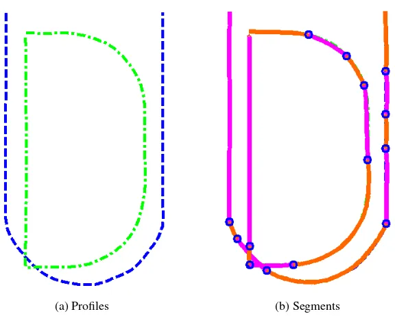
1.1.6 Artwork
For entertainment purposes, a mechanism that morphs between the letters “U” and “D” has been
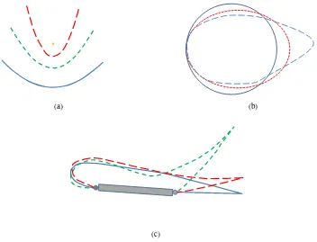
proposed [46]. The profiles and the set of rigid bodies that morph between the two letters are shown
(a) Profiles (b) Segments
Figure 10: (a) Design profiles define the shapes of the letters. (b) A chain of rigid-bodies connected by R joints approximates the two letters.
1.2 Various Shape-Changing Methods
There have been many emerging technologies developed for various applications. The main
ones include rigid-body mechanisms, compliant mechanisms, shape-memory effect materials and
membranes, as well as combinations of these with rigid-bodies.
1.2.1 Rigid-Body Shape-Change
Rigid body mechanisms are typically composed of familiar machine elements like linkages,
gears, cams, axles, etc. The theories governing their analysis are well established, explaining
accu-rately their kinematics and the forces encountered [47]. The design of systems composed of these
elements also has many well established methodologies, with many of the components
[image:32.612.180.468.79.310.2](a) (b)
[image:33.612.168.478.98.616.2](c) (d)
and design theories, rigid-body mechanisms readily produce large displacements while delivering
high load-carrying capacities. Potential drawbacks include backlash, wear, increase in part-count,
weight, assembly cost and time, and routine maintenance [48]. As rigid-body mechanisms are
com-mon and encounter significant use, these drawbacks are well addressed in most machine designs
[49, 50].
In this work, the rigid-body shape-changing mechanisms are composed of bodies connected by
revolute (R) and prismatic (P) joints. Examples of rigid-body shape-changing designs from Section
1.1 include the morphing wing in Fig. 2 and morphing car spoiler in Fig. 3, the convertible car
roof in Fig. 7, the mobile performance stage in Fig. 8, and the artwork example in Fig. 11. As the
complexity of some of these devices may indicate, an additional design challenge in several of these
examples is the identification of layering of the links in order to avoid interference [51, 52].
Generally, rigid-body mechanisms can be driven with a single actuator [14]. The input force or
torque can be applied to one of the links of the mechanism [53]. Actuation of rigid-body
mecha-nisms is typically achieved with various kinds of electric motors, ball screws, hydraulic and
pneu-matic cylinders, springs and elastic bands, and occasionally, human-power [14]. Electric motors like
AC motors, DC motors, geared motors, stepper motors, and servomotors provide rotary motion that
can be attached to a driving axle. Some motors are integrated with ball screw mechanisms to provide
linear motion. Hydraulic and pneumatic systems use hydraulic oil and air respectively to initiate
lin-ear motion in cylinders. Manual actuation by cranking and levering also see common use in many
mechanisms. Nonetheless, output motions can also be achieved by having multiple actuators such
as in many industrial robots. Kota and Erdman [54] argued that this is usually not an efficient use
of energy and should be considered primarily if flexibility in motion is required. In addition to the
widely-used actuators mentioned previously, mechanisms can be actuated by shape-memory alloys
Due to their well established principles and components, rigid-body mechanisms offer a
solu-tion worthy of considerasolu-tion in solving shape-change problems. Rigid-body shape-changing
mech-anisms have the potential to benefit from qualities such as high stiffness and large load carrying and
displacement capabilities.
1.2.2 Compliant Mechanisms
Shape-change may be accomplished by using compliant mechanisms, which can be designed in
a manner similar to rigid-body mechanisms [58]. Without hinges, though, compliant mechanisms
have the advantage of providing a smooth morphing boundary without discontinuities. Compliant
mechanisms usually have qualities of both a mechanism and a structure [34]. Howell introduced the
concept of the pseudo-rigid-body model to aid the design of compliant mechanisms [47]. Another
method used in their synthesis is topology optimization, which attempts to solve a design problem
by iteratively removing material from regions in a structure that are less sensitive to reducing the
overall structural stiffness and thus change its final shape [33, 34].
Section 1.1 lists many compliant shape-changing devices including a prosthetic hand, morphing
aircraft wing in Fig.1, and robotic gripper as in Fig. 9. Shuib et al. [48] show other applications
including compliant staplers and knee-joints. Additionally, there are also many biologically inspired
technologies including those for flapping wings [59] and artificial biomimetic robotic swimming fish
[60].
Goldfarb and Speich [61] mention that a benefit of compliant mechanisms is the absence of
revolute joints and bearings, thus eliminating mechanical backlash (from clearance) and Coulomb
friction (which causes wear). Parlaktas [62] added other potential advantages of compliant
and less noise. Mankame and Ananthasuresh [63] note that compliant mechanisms have the
advan-tages of being a single-piece and utilizing elastic deformation of the mechanism bodies instead of
kinematic joints, which is very useful at the micro level since they do not require assembly.
Com-pliant mechanisms also store elastic energy as they deform, so there is no need for springs to return
the mechanism to its original position. Consequently, this also means they require a holding force
in a deformed position.
Other disadvantages of compliant mechanisms include the relatively small range of motion,
imprecise axis-drift motion, off-axis stiffness, and high stress-concentration at the joints [61, 64].
Converting reciprocating translation to rotational motion is also a problem that requires alternative
approaches such as a contact-aided compliant mechanism [63]. The displacement achievable with
a compliant mechanism is limited by the elastic properties of its composing material, so it is quite
difficult to accommodate shape changes involving significant differences in arc length.
1.2.3 Membranes and Smart Materials
In space, a very large, deployable telescope can be made of segments of stretched reflective
membranes [37, 38]. Being lightweight and flexible, they can be transported in a compact
configura-tion. Section 1.1.3 included a coated deformable membrane mirror that changes shape significantly
when deployed [17, 32, 39]. Typically, after a mirror is deployed, the flatness of its flexible surfaces
requires correction. This may be accomplished via the use of electrostatic, electromagnetic, electron
gun or boundary actuation techniques in a closed-loop system [38, 65].
In another space application, Otsuka et al. [66] showcased a nickel-titanium alloy for a space
antenna as shown in Fig. 18. Smart materials typically change shape via an applied voltage, when
heated, or due to changes in magnetic force, humidity, or pH value [67, 68, 69, 70]. They can
is the shape-memory alloy (SMA), which may be classified as “way” or “two-way”. The
one-way materials may be deformed to change shape at low temperature. When heated above a certain
temperature, they start to revert to their original shape in the austenitic phase. A two-way SMA
material can assume two pre-trained shapes by certain thermomechanical treatments that depend on
heating or cooling at certain temperatures. This represents a limitation should there be more shapes
to be approximated. Research in wings and helicopter blades that utilize smart materials typically
incorporate piezoceramics or active fiber composites such as in Weisshaar et al. [10, 11], Cesnik et
al. [16], Wong [17], and Grohmann et al. [18].
1.2.4 Combinations Involving Membranes and Rigid Bodies
Many systems considered for shape change require smooth design profiles. However, rigid-body
rotation about discrete revolute joints will result in a profile with abrupt continuity changes that
may hinder the approximation of a smooth curve. Recent advancements in membrane technology
for mirrors, aeronautics, and automotives could be coupled with rigid-body mechanisms to address
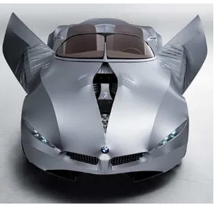
this issue [72, 57]. For instance, BMW is investigating shape-changing cars that are covered with
plastic-coated lycra fabric that is stretched over a metal frame with moving components. This
concept car, GINA [73], is shown in Fig. 12.
1.3 Rigid-Body, Shape-Changing, Mechanism Design Methodology
This section overviews the established design process for planar rigid-body shape-changing
mechanisms that includes design profile specification, target profile generation, segmentation, and
Figure 12: The “skin” or outer layer of the shape-changing machine does not have to be rigid. The GINA has the skeleton mechanism underneath made of rigid members [73].
1.3.1 Profiles and Segmentation
Planar rigid-body shape-changing mechanism design begins with a set of design profiles, such as
airfoil profiles for loiter and attack modes. The synthesis process proceeds by representing each of
the design profiles in a standardized manner, such that comparisons can be made among them. This
standardized representation is a coordinated set of points on the design profiles defining a
piecewise-linear curve that is termed the target profile. The design process continues with a segmentation phase
that creates segments, which are generated in shape and length so that they form a jointed chain
of rigid bodies that approximate corresponding segments on each target profile. To complete the
synthesis, a mechanization phase typically adds binary links to each segment in order to achieve the
lowest degree-of-freedom (DOF) linkage possible. Although this established process of designing
a rigid-body shape-changing mechanism remains true for this work, substantial changes are needed
1.3.2 Mechanization Methods
A system with a low DOF is commonly preferred for simplicity in control [74, 75]. The
mechanization phase involves adding rigid constraining links and joints, forming a mechanism that
smoothly transitions the shape approximating chain between the target profiles with a limited
num-ber of actuators. In many applications, the reduced cost and control requirements of fewer actuators
outweighs the kinematic complexity. When a single-DOF system is desired and the number of
tar-get profiles is less than or equal to five, it is theoretically possible to add binary links without further
increasing the profile matching error. The dimensional synthesis task for rigid body guidance
iden-tifies appropriate circle points on the rigid links of the shape approximating chain and center points
on the frame. Machine theory texts, such as McCarthy [76], provide methods for dimensional
synthesis for rigid body guidance. However, it was revealed through experience that eliminating
circuit, branch and order defects becomes problematic when more than three profiles are involved.
Balli and Chand [77] provided a thorough discussion on solution rectification. Consequently, for
two and three profiles, the mechanization of shape-changing linkages has been accomplished by
adapting dimensional synthesis techniques to Geometric Constraint Programming (GCP) with a
computer-aided design package as in Kinzel et al. [78].
For greater than three profiles, mechanization of rigid-body shape-changers is performed as
outlined in Murray et al. [46, 79]. Least-squares approximations such as those developed by Yao
and Angeles [80] can be used to locate circle and center points for each segment. The structural
error associated with such approximate motion synthesis methods will further increase the shape
approximating error. A search algorithm is implemented to examine many circle and center point
pairs, designating candidate designs as those that produce an acceptable level of structural error.
The candidate designs are then evaluated to determine whether they can be actuated monotonically
can be ranked by a quality factor of the designer’s choosing. This search approach does not yield
optimal designs in any formal sense, but produces a number of viable designs that can be evaluated
according to various metrics. Expanding on the search process, Zhao et al. [81] illustrate how
genetic algorithms can be used to synthesize planar rigid-body shape-changing mechanisms. Once
a successful mechanism has been formed, it may benefit from the addition of a coupler driver to
reduce actuator effort and avoid mechanism defects [82].
The mobility of a final design is not necessarily restricted to a single DOF or being driven by
linkages formed from rigid bodies. There are many other possibilities of actuating a chain of
rigid-bodies from one position to another. Cable and spring mechanisms [83, 84], smart-material
actu-ators like piezoceramics [71], and multiple-motor actuation [54] can all be considered. Figure 13
shows a segmented prosthetic finger that can bend into a curled shape by tensioning its cable [83].
Alternately, robotic systems are typically serial links actuated at every joint. This dissertation does
not focus on the mechanization stage of the work and an ad-hoc method is used to complete
sev-eral examples in Chapter V. Regardless of the fact that a mechanization is shown, the chain may
be controlled in a variety of ways with additional consideration given to the appropriate degrees of
freedom.
1.3.3 Limitations of This Method
When two profiles are not similar in arc length, the resulting mean profile does not approximate
either of the two profiles well. This, however, depends on the significance of the difference in arc
lengths. Figure 14a illustrates the mean segment generated for points 1 through 3 of the profiles,
whereas Fig. 14b shows two copies of the mean segments being placed on top of the two original
segments. Obviously, the mean segments do not approximate any portion accurately. Another
problem is that the method is not capable of assigning a segment type that can change length.
Hence, there is a need for another method to solve different arc-length problems.
(a)
(b)
1.4 Shape-Changing for Different Arc-Length Profiles
Some examples of shape-changing mechanisms that have different arc-length profiles include
wings, boat hulls, satellite antenna, and forming dies. This dissertation proposes new methodologies
for the design of rigid-body shape-changing mechanisms that approximate design profiles with
sig-nificant differences in arc length. This affects both the profile generation and segmentation phases.
1.4.1 Different Arc Length Examples
Many large aircraft wings have multiple elements to achieve the required lift and drag for
dif-ferent flight modes. When in operation, some of these elements are deployed to effectively extend
the profile of the wings. Figure 15 shows a pressure distribution plot for a four-element wing [85],
which is an example of different arc length profile for a shape-changing mechanism.
Wong [17] highlights the idea of a shape-changing boat hull that can affect maximum speed,
ride comfort, and fuel consumption. Several basic foil shapes used by naval designers are shown
in Fig. 16. These also show the need for different arc-length shape-changing mechanisms since
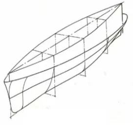
the profiles’ perimeter are significantly dissimilar. Gillmer [26] explained that modern ship designs
employ modifications of these throughout sections of the hull as illustrated in Fig. 17. While overly
ambitious for large sea-going ships, a shape-changing hull is an attractive concept that would enable
much smaller boats to make adjustments for the navigation of seas, rivers, lakes, swamps etc.
[image:43.612.255.391.443.572.2](a) Planing (b) Deep hull (c) Multi hull (d) Round hull (e) Deep vee
Figure 16: The various types of hulls for ships and boats.
Figure 17: Different cross-sectional shapes along a modern ship’s hull [26].
Goodyear Aerospace Corporation studied the use of Ti-Ni shape-memory effect (SME) wires
spatial environment. Figure 18 shows the progression as the deformed wires revert back to the
original shape of the antenna through solar heating.
(a) Deformed shape (b) Interim shape 1
(c) Interim shape 2 (d) Fully deployed shape
Figure 18: The Ti-Ni wires return to its original antenna shape by heating [66].
Altering an extruded plastic profile by sliding segments of the die orifice in a controlled manner
[86] may also be considered a shape change. Choi et al. [87] investigated the forming of aluminum
frames for automotive applications through the use of a CNC variable section extruder. Figure 19
shows the schematic diagram of their experimental setup and the finished product that has different
cross-sections at opposite ends. Note that the perimeters of the sections exhibit drastically different
arc lengths. O’Connor proposes a method to produce a pultruded thermoplastic composite body
having at least two integral sections of different cross-sectional shapes [88]. The system arranges
different sets of dies in series as illustrated in Fig. 20a. Potential varying cross-section pultrusions
(a) (b)
Figure 19: (a) Schematic diagram of the multiple dies extrusion system. (b) The frame is axially twisted, and the width of the cross section varies steadily [87].
(a)
(b)
[image:45.612.207.445.327.627.2]Murray et al. studied the design of a shape-changing extrusion or pultrusion die [89]. Different
arc-length profiles can be seen in Fig. 21a and the extrusion machine that is designed to produce
such shapes is shown in Fig. 21b.
(a) (b)
Figure 21: (a) Various cross-section shapes for the two extruded products. (b) The shape-changing die concept [89].
1.4.2 New Profile Generation
The curves that are specified as the desired shapes to be matched by the edge geometry of rigid
links are called design profiles. Points are generated along each design profile that when connected
by line segments, approximate the design profiles. These new curves are called the target profiles.
The line segment connecting two adjacent points is called a piece. Correspondingly, the number
of pieces will be one less than the number of points on each target profile. Since profiles can have
different arc lengths, the number of points used may not be identical from one design profile to
another. Murray et al. [46] assign the same number of points to each target profile. With significant
differences in arc length, this work assigns a different number of points to each profile, distributed
allow for the inclusion of rigid bodies connected with prismatic joints, which can vary the length.
As the desired piece length is made smaller, the generated profiles better approximate the shapes of
the design profiles.
1.4.3 New Segmentation Method
Segmentation is the second phase of the design process. The goal of this phase is to create
segments that are generated in shape and length so as to form rigid links that approximate
corre-sponding segments on each target profile. Connecting these segments with revolute joints yields
a chain of bodies that approximates the target profiles and hence, the design profiles. There are
two basic types of segments, the mean segment (M-segment) and the constant curvature segment (C-segment).
When a segment contains the same number of points on each target profile, an M-segment is generated. The segments are transformed to the corresponding segment on a reference profile
in distance minimizing configurations. The M-segment is generated as the geometric center of each set of corresponding points before being transformed back to approximate the corresponding
segments. A poor match may be improved by reducing the number of points being matched or
changing start and end points.
When a different number of points on each target profile are to be approximated, aC-segment is generated. By calculating an average radius of constant curvature and an average piece length, a
segment of constant curvature is generated. As with theM-segment, a poor match may be improved by reducing the number of points being matched or changing start and end points.
M- andC-segments that approximate all pieces on all target profiles are assembled by joining their end points with revolute joints. These assembled chains are repositioned to best match each
-andC-segments may be changed, the length of each segment may be changed, or the number of segments may be increased.
In addition to the two basic types of segments, a third type of segment may be formed by fusing
anM- and aC-segment or twoC-segments. Segments are fused after they are joined as a chain and aligned with the profiles. Should the relative rotation about an R joint be small, fusing of the
segments is considered. Note thatM-segments are not fused with otherM-segments.
1.5 Organization
With the goal of segmentation of a set of design profiles of significantly different arc length
into a chain of rigid-bodies connected by R and P joints, this dissertation is organized as follows.
Chapter II discusses the creation of target profiles when the arc lengths of the design profiles are
significantly different. Having created the target profiles, Chapter III explains the generation of
M- andC-segments. The
M
ATLAB software implementation that enables the design of segments to be carried out is explained in Chapter IV. Chapter V discusses several mechanization examplesin which different profiles serve to show the utility of the methods developed in this work. Lastly,
conclusions and suggestions for future work are furnished in Chapter VI. A user’s guide in Appendix
A provides examples of how to use the software to create a chain of jointed segments from a set of
CHAPTER II
OPERATIONS ON TARGET PROFILES
The first goal of this chapter is to showcase the process for creating target profiles from a set
of design profiles. Design profiles specify the design challenge in that they are the set of curves
used to describe the shapes that the shape-changing mechanism should approximate. Target profiles
are the set of curves generated from the design profiles but defined by points spaced to facilitate
approximation by a connected chain of rigid links. Once generated, target profiles replace the
design profiles and are used in all following processes to create the chain of links. The second goal
of this chapter is to establish the metrics by which distance between target profiles or their segments
can be determined.
2.1 Target Profile Generation
The challenge posed by shape-change is the specification of a set ofpdesign profiles that rep-resent the different shapes to be attained by the mechanism. Murray et al. [46] define a design
profilejas an ordered set ofnjpoints for which the arc length between any two can be determined. Figure 22 exhibits the three types of design profiles considered: open, closed, and fixed-end
pro-files. While the illustrative examples shown in this work are for the open profile case, this research
(a) (b)
[image:50.612.151.503.81.350.2](c)
Figure 22: Profile types include (a) open profiles, (b) closed profiles, and (c) fixed-end profiles.
Given the definition of design profiles, they may be viewed as being piecewise linear. A piece
is the line segment connecting two contiguous points on a profile. Theithpoint on thejthdesign profile is designated{aji, bji}
T
. The length of theithpiece on thejthdesign profile is
cji = q
aji+1−aji 2
+ bji+1−bji 2
, (1)
and the arc length of the entirejthdesign profile is
Cj = nj−1
X
i=1
cji. (2)
The design profiles may be defined by any number of points spaced at various intervals, producing
As previously defined, target profiles are a set of curves that represent the set of design profiles.
They have common features so that groups of contiguous points can be compared to all profiles in
order to form a suitable chain of rigid bodies that when repositioned will approximate all design
profiles. In earlier work [46, 79], the design profiles were assumed to be of roughly equal arc
lengths, C1 ≈ C2 ≈ . . . ≈ Cp, and each target profile can be formed by distributing the same n number of defining points equally along the corresponding design profile. The target profile
becomes a piecewise linear curve composed of pieces with roughly the same length, cji ≈ ckl,
∀i, j, k, l. Constant piece lengths allow for identification of corresponding points on each target profile.
The general profiles discussed in this work may possess substantial differences in arc length.
Using the same number of points on different length profiles would result in different piece lengths
and contaminate the shape comparisons among groupings of contiguous points. In order to produce
a constant piece length, the conversion scheme from design to target profiles must be modified from
the established method to allow for a different number of points on each target profile. By specifying
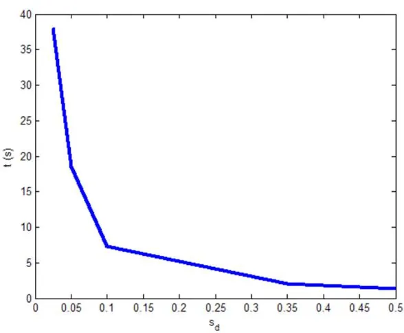
a desired piece lengthsd, the number of piecesmj on profilejcan be determined. Smaller values ofsd will produce more pieces and typically result in smaller variations between the design and target profiles. Experiments have shown as the number of pieces increases, the time it takes to
complete the synthesis increases exponentially. Hence, sd needs to be controlled to achieve the desired accuracy in an acceptable computation time. Figure 23 shows the exponential relationship
betweensdand the computation time done on a machine with IntelR CoreTM i5 M540 processor at 2.53GHz with 4.00 GB total memory. The usable space, however, is 2.98 GB and the system is
32-bit. This experiment used the three-profile example with four segments that is shown in Fig. 25.
Figure 23: Computation time decreases exponentially assdincreases in size.
The number of pieces must be an integer, and an initial value is calculated as
mj =
Cj sd
, (3)
where⌈ζ⌉ represents the ceiling function, the smallest integer not less thanζ. Provisional target profiles are generated by distributingnjpoints at increments ofCj/mj along thejthdesign profile. A distribution of target profile points along a design profile is shown in Fig. 24. The jth target profile becomes a piecewise linear curve connecting the ordered set of pointszj
i = {xji, yji}
T ,
i= 1, ..., nj. The length of theithlinear piece on thejthtarget profile is
sji =
zji+1−zji
=
q
xji+1−xji 2
+ yji+1−yji 2
. (4)
The corresponding number of points on the target profilejisnj =mj+ 1.
j=1
)
,
(
1 1 1 1y
x
)
,
(
2 2 1 1y
x
)
,
(
3 3 1 1y
x
)
,
(
5 5 1 1y
x
)
,
(
4 4 1 1y
x
2 1
s
C
1/m
11 1
s
3 1
s
4 1
s
Figure 24: Design profile (solid) with an approximating target profile (dashed) where points are positioned to give a constant arc length along the design profile.
of the design profile results in piece lengths shorter thansd, as seen in Fig. 24. That is, some piece sji = sdonly whensd divides exactly intoCj andthe design profile has a zero curvature portion
long enough to include the entire piece. The average piece length for thejthprofile is
¯
sj =
1
mj
nj−1 X
i=1 sji
. (5)
As the provisional target profile is constructed to (potentially) have too many pieces to
accu-rately achievesd, the likely scenario is that fewer pieces will produce a value of ¯sj closer to sd. An error representing the difference between the average segment length and desired piece length is
calculated asǫsj =|sd−s¯j|. Decreasingnj by 1 and redistributing points along the design profile
creates a new target profile. Points are removed untilnj = n∗j (and correspondingly,mj = m∗j) that minimizesǫsj. The end result is the fewestn
∗
j points are used to construct thejthtarget profile such that all linear piece lengths are approximately equal to the desired piece length. Desirable
target profiles are those with the fewest pieces that achieve the accuracy needed to satisfactorily
approximation of the design profiles. Conversely, as the calculations presented in the later sections
are dependent on this number, having fewer pieces reduces computation time.
After eachm∗j is established, the total length of thejthtarget profile is calculated as
Sj = m∗
j X
i=1
sji. (6)
Applying this process to all design profiles, p target profiles are constructed such that all linear pieces have lengths that are approximately equal tosd. The average length of allm∗j linear pieces on allpprofiles is
¯
sm=
Pp
j=1 Sj
Pp
j=1m∗j
. (7)
If the representation of the design profiles lacks the desired accuracy, a smaller desired piece length
may be used to increase the number of points defining the target profiles.
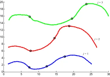
Three target profiles are shown in Fig. 25. The lengths of the design profiles areC1 = 26.1738, C2 = 31.0847, andC3 = 34.4737. For a desired piece length ofsd = 0.35, the target profiles
have m∗1 = 76, m∗2 = 90, and m∗3 = 99 pieces. The average piece length issm¯ = 0.3499and the lengths of the target profiles areS1 = 26.1669,S2 = 31.0760, andS3 = 34.4562. Although S1/C1 = 0.9997,S2/C2 = 0.9997, andS3/C3= 0.9995in this example, the heuristic in this work
is to setsdsuch thatSi/Ci ≥ 0.99for all profiles in the set unless the design problem dictates a specific accuracy. Values are reported in this initial example to four decimal places to highlight the
minor differences between design and target profile lengths and desired and achieved piece lengths.
The four decimal places are not meant to suggest that these are significant figures.
2.2 Metrics on Target Profiles
0 5 10 15 20 25 30 0
2 4 6 8 10 12 14 16 18 20
j = 1
[image:55.612.143.505.74.328.2]j = 2 j = 3
Figure 25: Three design profiles with significantly different arc lengths represented with target profiles of nearly constant piece length.
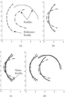
these profiles is determined. Three such profiles are shown in Fig. 26a. Denoting the points on
the “reference profile” asZ1
i and those on one of the other two profiles (the dash-dot profile, for
example) as zj
i, the values of rotation matrix Aj and displacement vectordj are calculated that
solve Eqs. (8) and (9) under the restriction of scale b = 1. This restriction is necessary due to the consideration of these points as representing rigid bodies. Figure 26b shows both of the target
profiles aligned with the reference profile in this way. Continuing with the design of a rigid-body
shape-changing mechanism, a “mean profile” is generated from the geometric center of each Z1
i
and the shiftedzj
i, as shown in Fig. 26c. Using additional similarity transformations, the mean
all of the target profiles in order to create a mean segment and to move this mean segment back to
the locations nearest the original target profiles.
(a) (b)
(c) (d)
Figure 26: (a) Three target profiles, with one deemed the reference profile. (b) Two profiles are transformed to the reference by a similarity transformation (withb= 1). (c) The mean profile. (d) The mean profile transformed back to the original profile locations [46].
If the design goal were to find a single body to approximate the three target profiles, the
[image:56.612.199.450.148.523.2]in Fig. 26d can be determined. Should this fail to reproduce the original profiles with adequate
accuracy, the process described above can be performed on individual portions of the target profiles.
Figure 27a shows an example in which the three target profiles are considered to consist of four
seg-ments. Each segment now does a better job of approximating a shorter section of the original target
profile, and combining these segments into a single chain connected by revolute joints produces a
more accurate matching of the original target profiles. Figure 27b shows the complete mechanism
that can be used to move the chain between the three profiles. Note that increasing the number of
segments increases the complexity (the number of links) of the mechanism that guides the segments
along the three profiles. The details of this process are found in Murray et al. [46] and Persinger et
al. [79].
(a) Segmentation (b) Mechanization
Figure 27: (a) Rigid bodies connected with revolute joints form a chain to closely approximate the profiles. (b) A mechanism design that moves the chain of rigid bodies between the three profiles.
The application of a similarity transformation in mechanism analysis is not far different from
the needs in the image registration community. Zitov´a and Flusser [90] identified a critical step in
image registration defined as “transform model estimation.” In this step, one attempts to identify the
reference image. In planar cases, this mapping function is restricted to be a similarity transformation
that can be solved in closed-form as
Zji =bAjzji+dj, (8)
wherezji are the points in the sensed image,bis a scaling factor,Aj is a rotation matrix, anddj is
a displacement vector. The desired values ofb,Aj, anddj are those that minimize
D(Aj,dj, b) =
1
N N
X
i=1
|Zji −Z1i|
2
, j= 2, . . . , p, (9)
where, for clarity,Z1i = (Z1xi, Z1yi)are the points in the reference image andZji = (Zjxi, Zjyi)
are the points in the transformed image.
The solution to Eq. (8) that minimizesDin Eq. (9) has been thoroughly addres
![Figure 7: A soft-top convertible roof [40].](https://thumb-ap.123doks.com/thumbv2/123dok/549810.64573/30.612.194.455.304.627/figure-a-soft-top-convertible-roof.webp)
![Figure 11: The mechanism is capable of moving the chain from approximating the “U” to the “D”as it progresses from (a) through (d) based on work in [46].](https://thumb-ap.123doks.com/thumbv2/123dok/549810.64573/33.612.168.478.98.616/figure-mechanism-capable-moving-chain-approximating-progresses-based.webp)
![Figure 19: (a) Schematic diagram of the multiple dies extrusion system. (b) The frame is axiallytwisted, and the width of the cross section varies steadily [87].](https://thumb-ap.123doks.com/thumbv2/123dok/549810.64573/45.612.207.445.327.627/figure-schematic-diagram-multiple-extrusion-axiallytwisted-section-steadily.webp)