RADIO-FREQUENCY IDENTIFICATION (RFID) TEXTILE TAG ANTENNA
MOHAMAD AMIN BIN ABU ZAKA
i RADIO-FREQUENCY IDENTIFICATION (RFID) TEXTILE TAG ANTENNA
MOHAMAD AMIN BIN ABU ZAKA
This report is submitted in partial fulfillment of the requirement for the award of Bachelor of Electronic Engineering (Wireless Communication) with Honors.
Faculty of Electronic and Computer Engineering Universiti Teknikal Malaysia Melaka
v
vi
ACKNOWLEDGEMENT
I wish to express my deep sense of gratitude to my supervisor, Dr. Maisarah Binti
Abu for her able guidance and useful suggestions, which helped me in completing the project work, in time.
Great deals appreciated go to my fellow friends and all Faculty of Electronic and Computer Engineering (FKEKK) that patient in helping me complete this project either directly or indirectly. Thank you very much.
vii
ABSTRACT
viii
ABSTRAK
ix
TABLE OF CONTENT
CHAPTER MATTER PAGES
PROJECT TITTLE i
PSM STATUS VERIFICATION FORM ii
DECLARATION iii
SUPERVISOR VERIFICATION FORM iv
DEDICATION v
ACKNOWLEDGEMENT vi
ABSTRACT vii
ABSTRAK viii
TABLE OF CONTENT ix
LIST OF FIGURES xiii
LIST OF TABLES xiv
LIST OF ABBREVIATIONS xv
I INTRODUCTION TO PROJECT 1
1.1 INTRODUCTION 2
1.2 PROBLEM STATEMENT 3
1.3 OBJECTIVE 3
x
1.5 METHODOLOGY 4
1.6 THESIS OVERVIEW 5
II LITERATURE REVIEW 7
2.1 RFID HISTORY 8
2.2 RFID WORKING CONCEPT 9
2.3 RFID SYSTEM ARCHITECTURE 10
2.3.1 RFID Tag 11
2.3.1.1 Passive RFID Tag 11 2.3.1.2 Active RFID Tag 13 2.3.1.3 Semi-active RFID Tag 14
2.3.2 RFID Reader 15
2.3.3 Host and Software System 16 2.3.3.1 Edge Interface/System 16
2.3.3.2 Middleware 16
2.4 BASIC CONSIDERATION OF RFID TAG 17
2.4.1 Antenna Types 18
2.4.2 Impedance Matching 18
2.4.3 Radar Cross Section (RCS) 20
2.4.4 Size of Tag Antenna 20
2.4.5 Surface Material Properties 21 2.4.6 Radiation Pattern and Antenna Polarization 21
2.5 IMPEDANCE MATCHING 22
2.5.1 Delta Match 22
xi
2.5.3 LC Network Match 25
2.5.4 Transformer Matching 25
III METHODOLOGY 27
3.1 PROJECT IMPLEMENTATION 27
3.2 ANTENNA PARAMETERS 30
3.2.1 Radiation Pattern 30
3.2.2 Directivity 31
3.2.3 Gain 32
3.2.4 Polarization 32
3.2.5 Return Loss 33
3.3 PROJECT DESIGN 34
3.4 FABRICATE PROCESS 37
3.5 TESTING PROCESS 38
IV RESULT AND DISCUSSION 39
4.1 CHAPTER OVERVIEW 39
4.2 RFID CONCEPT IN STORES 40
4.3 TEXTILE PERMITTIVITY 40
4.4 SIMULATION RESULTS 42
4.5 PARAMETRIC STUDY 45
xii
V CONCLUSION AND RECOMMENDATION 55
5.1 CONCLUSION 55
5.2 RECOMMENDATIONS 56
xiii
LIST OF FIGURES
FIGURES TITTLE PAGES
1.1 Block Diagram of RFID System 2
2.1 Passive RFID Tag System 12
2.2 Active RFID Tag System 13
2.3 Delta Match Technique 23
2.4 The Quarter Wavelength Impedance Matching 24
2.5 List of Matching Method 25
2.6 Transformer Type Impedance Matching 26
3.1 Flow Chart for PSM 1 Activities 28
3.2 Flow Chart for PSM 2 Activities 29
3.3 Design of RFID Textile Tag Antenna in Simulation 36
3.4 RFID Transponder Equivalent Circuit 36
4.1 RFID Technology Applied in Store 40
4.2 Permittivity of Jeans Measured in Laboratory 41 4.3 The Front View of Tag Antenna in Simulation 42 4.4 The Back View of Tag Antenna in Simulation 43
4.5 The 3D View of Gain of Antenna 44
xiv
4.7 The Matching Between Tag Antenna and Chip 45 4.8 The Parameters Used in Parametric Study 46 4.9 The Simulated Return Loss with Different Value of L1 for textile
Tag antenna. 46
4.10 The Simulated Return Loss with Different Value of L2 for textile
Tag antenna. 47
4.11 The Simulated Return Loss with Different Value of L3 for textile
Tag antenna. 48
4.12 The Simulated Return Loss with Different Value of L4 for textile
Tag antenna. 49
4.13 The Simulated Return Loss with Different Value of W1 for textile
Tag antenna. 50
4.14 The Simulated Return Loss with Different Value of W2 for textile
Tag antenna. 51
4.15 The Simulated Return Loss with Different Value of W3 for textile
Tag antenna 52
4.16 The Simulated Return Loss with Different Value of W4 for textile
Tag antenna 53
xv
LIST OF TABLES
TABLE TITTLE PAGES
4.1 List of Textile and Its Permittivity 41
4.2 The Simulation Result of RFID Textile Tag Antenna 43
4.3 Results of Impedance Matching 45
4.4 Results of L1 Slot 47
4.5 Results of L2 Slot 48
4.6 Results of L3 Slot 48
4.7 Results of L4 Slot 49
4.8 Results of W1 Slot 50
4.9 Results of W2 Slot 51
4.10 Results of W3 Slot 52
xvi
LIST OF ABBREVIATIONS
RFID - Radio-frequency Identification
LOS - Line of sight
RCS - Radar cross-section
MW - Microwave
FR-4 - Flame Retardant #4
CST MWS - Computer Simulation Technology
Microwave Studio
IFF - Identify Friend or Foe System
LF - Low frequency
HF - High frequency
UHF - Ultra-high frequency
SR - Shortening radio
PSM 1 - Projek Sarjana Muda 1
PSM 2 - Projek Sarjana Muda 2
EMC - European Muon Collaboration
MPA - Microstrip Patch Antenna
UTeM - Universiti Teknikal Malaysia
Melaka
1
CHAPTER I
INTRODUCTION TO PROJECT
2
1.1 INTRODUCTION
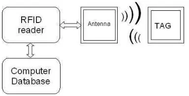
[image:19.612.234.426.271.369.2]Radio-frequency identification (RFID) is a generic term that is used to describe a system that transmits data from an electronic tag through a reader for the purpose of identifying and tracking the objects using radio waves. RFID is in use all around us. It has been used in a toll booth, supermarket and even in your house. Some tags can be read from several meters away and beyond the line of sight (LOS) of the reader.
Figure 1.1: Block Diagram of RFID System
Figure 1.1 shows the block diagram of RFID system. Most RFID tags contain at least two parts. The integrated circuit for storing and processing information, modulating and demodulating a radio waves signal and the antenna for purposes of receiving and transmitting the signal. Plus, a technology called chip less RFID allows for discrete identification of tags without an integrated circuit, thereby allowing tags to be printed directly onto assets at lower cost than traditional tags.
3 properties and radiation pattern and antenna polarization. All this will be evaluated to ensure the designed antenna work properly.
1.2 PROBLEM STATEMENT
RFID system nowadays is widely used in various applications from simple application to advance tracking application. Most of the RFID tag antenna used in that system operates in single band frequency which limit it operation. Plus, the tag itself used Flame Retardant #4 (FR-4) boards as the material for the antenna to mount. The tag antenna will be more versatile and apply in applications that previous tag cannot be.
1.3 OBJECTIVE
4
1.4 SCOPE OF WORKS
This project covers several scopes in accomplishing the project objectives. Basically this project is about designing an antenna for a transponder using new material as the substrate of antenna. In order to design the antenna, the understanding of the RFID architecture is vital to make the antenna work. It can be achieved through analysis and understand the related documentation of structured antenna types and any related research regarding antenna design. The next scope of works is to measure the permittivity of the textile used as the substrate of the antenna. This measurement is important to use in antenna simulation processes. Moreover, the works also include the determination of parameters that will be used in designing the antenna. The next crucial part is the simulation of the antenna. This is the part where the tag antenna’s design to meet the specifications using Computer Simulation Technology (CST) Microwave Studio software. After the simulation successfully conducted, the following works is to fabricate and test the antenna designed in real life environment and validate the results with existing research.
1.5 METHODOLOGY
5 searching for the chip is going to begin. The last part is RFID tag textile antenna development where involve a lot of laboratory works. In this part, the process of patching the antenna to the textile and compare its result to the simulated results and verified the outcomes of the project.
1.6 THESIS OVERVIEW
Chapter I gives an overview of dual band textile RFID tag antenna system and design. The objective of the project is stated clearly. There are few problem statements that explain about the existing problems which eventually lead to this project development. The scope of work explains details about what necessary to be done during period of this project development. The methodology explain briefly about the project flow from the beginning which is the background study, the textile’s permittivity examined, the simulation of the tag antenna and the development of the tag antenna in laboratory.
Chapter II consists of theories and background study on RFID system especially RFID tag antenna. This is followed by the history of the RFID system, the working concept of the RFID system, the architecture of the RFID system and design consideration and parameters of the textile RFID tag antenna.
6 RFID tag antenna development. After it is done, the integration between designed tag antennas with RFID reader is done to ensure the system capability.
Chapter IV discusses of the output of the projects. The results are divided into two parts which are the simulation result using CST Microwave Studio and testing result using Network Analyzer. In this process, the impedance matching between the chip and designed antenna is the important part to ensure the designed tag antenna works at the demand frequency band.
7
CHAPTER II
LITERATURE REVIEW