FORWARD KINEMATICS SOLUTION FOR 5 DEGREE OF FREEDOM OF RHINO XR-3 ROBOT
Mohd Norhisham Bin Che Soh
“I hereby declared that I have read through this report and found that it has comply the partial fulfillment for awarding the degree of Bachelor of Mechatronic
Engineering”
Signature : ……….
Supervisor‟s Name : Pn Irma Wani Binti Jamaludin
FORWARD KINEMATICS SOLUTION FOR 6 DEGREE OF FREEDOM OF RHINO ROBOT
MOHD NORHISHAM BIN CHE SOH B 010510101
This Report is Submitted in Partial Fulfillment of Requirements for the Degree of Bachelor in Mechatronic Engineering
FACULTY OF ELECTRICAL ENGINEERING UNIVERSITI TEKNIKAL MALAYSIA MELAKA
“I hereby declared that this report is a result of my own work except for the excerpts that have been cited clearly in the references.”
Signature : ………
ACKNOWLEDGEMENT
Alhamdulillah, finally the Final Year Project (FYP ) is complete. I take a great pleasure in this opportunity to thank many persons who generously advice and assists me while I was doing my FYP which is compulsory to all Universiti Teknikal Malaysia Melaka (UTeM) students to pass before awarded the degree.
First of all, I would express my deepest thanks and gratitude to my project supervisor, Pn Irma Wani bt Jamaludin for undivided support morally and physically, assistance, guidance, tolerance, which proved to be invaluable as to the completion of my FYP.
I also would like to thank the panel, Mr. Ahmad Zaki bin Shukor, Mr. Farez bin Ali@Ibrahim, Pn Nur Ilyana Anwar Apandi and Mr. Farhan Bin Hanaffi whose give me a good comment during my presentation. I also would like to take this opportunity to express my appreciation to my family and friends for their patients, understanding and also for their undivided support that they had gave me throughout the completion of my project.
ABSTRACT
ABSTRAK
TABLE OF CONTENT
CHAPTER CONTENT PAGE
ACKNOWLEDGEMENT i
ABSTRACT ii
TABLE OF CONTENT iv
LIST OF TABLES vi
LIST OF FIGURES vii
LIST OF ABBREVIATIONS viii
1 INTRODUCTION 1
1.1 Background of the Project 1
1.2 Objective 2
1.3 Scope 3
1.4 Problem Statement 3
2 LITERATURE REVIEW 4
2.1 DK Analysis of 5 Axis Rhino XR-3 Robot 4 2.2 Sirf Rhino (RhinoGui Interface) 5 2.3 Kinematics Analysis Program (KAP) 6
2.4 Forward Kinematics 9
2.4.1 Denavit Hartenberg Representation 10
2.5 Rhino XR-3 Robot 12
2.5.1 Forward Kinematics of Rhino XR-3 12
3 PROJECT METHODOLOGY 15
3.1 Overview 15
3.2 Study and Research 17
3.4 Developing an Algorithm 17 3.5 Design & Develop Graphical User Interface 18
4 RESULT AND ANALYSIS 19
4.1 Overview 19
4.2 Features of fkRhino 19
4.3 Using fkRhino Software 21
4.4 Microsoft Visual Basic Command for fkRhino 22
4.5 Errors in fkRhino 31
4.6 Discussion 33
5 SUMMARY AND CONCLUSION 35
5.1 Summary 35
5.2 Conclusion 35
5.3 Recommendation 36
LIST OF TABLES
TABLE TITLE PAGE
2.1 Robot DH-parameter table. 8
LIST OF FIGURES
FIGURE TITLE PAGE
2.1 RhinoGui interface. 6
2.2 GUI of KAP5. 7
2.3 Functional Block Diagram of KAP 8
2.4 Link Parameter. 10
2.5 Rhino XR-3 robots. 12
2.6 DH link frame assignment of Rhino XR-3 robot. 13
2.7 Rhino robot attached to a table. 13
3.1 Flow of the Project Methodology. 16
4.1 GUI of fkRhino. 20
4.2 Welcome Screen of fkRhino. 21
4.3 GUI of Invalid Property Value. 31
4.4 GUI of Type mismatch. 32
LIST OF ABBREVIATIONS
LIST OF APPENDICES
NO. TITLE PAGE
Appendix 1 Project Planning 39
Appendix 2 Program for DK Analysis of 5 Axis Rhino Xr-3 Robot 41 Appendix 3 Specification of Rhino XR-3 Robot 49
Appendix 4 fkRhino Command 51
INTRODUCTION
The “Forward Kinematics Solution for 5 Degree of Freedom of Rhino XR-3 Robot” project is to identify and develope the programming software which is to design the graphical user interface (GUI). This GUI will be used to solve the forward kinematics problem for 5 DOF of Rhino XR-3 robot. This chapter will discuss about the background of the project, its concept, objective, scope of the project and the problem statement.
1.1 BACKGROUND OF THE PROJECT
Kinematics is the science of motion which treats motion without regard to the forces that causes it [1]. While the forward kinematics problem of Rhino XR-3 robot is to compute the position and orientation of the robot‟s end-effectors relative to the base of the robot [8].
In order to solve the kinematics problem, a conventional method which has a lot of complexity equation and calculation must be applied. However, it is hard to be implemented in practice even many industrial robots are built with simple geometries to simplify the associated kinematics computations such as Rhino XR-3 robot.
1.2 OBJECTIVE
The main objective of this project is to solve a forward kinematics problem for 5 DOF of Rhino XR-3. In order to solve the problem, the suitable programming software will be identified and then the algorithm will be developed. After that, a user friendly GUI will be developed. Specific objectives of this project are:
i. To identify a suitable programming software for solving forward kinematics equation.
ii. To develop an algorithm based on the programming software.
iii. To design a graphical user interface by using the identified of programming software and solve the forward kinematics problem for Rhino XR-3.
1.3 SCOPE
The scope of this project is cleared where this GUI is developed for solving the forward kinematics problem only for Rhino XR-3 robot. The GUI is also developed only for calculation the final position without any simulation of the operation of this robot. Thus, this GUI is not suitable to other type of robot unless both algorithm and GUI is modified.
Many industrial robots are built with simple geometries such as intersecting or parallel joint axes to simplify the associated kinematics computations. The mathematical complexity of solving robots of general architecture detracts instructors and students from using robots with arbitrary structures in illustrative examples and assignments [2].
CHAPTER 2
LITERATURE REVIEW
In this chapter, a review of previous research project that are related with this project will be discussed. The information about forward kinematics and Rhino XR-3 robot are also described in this chapter.
2.1 DK ANALYSIS OF 5 AXIS RHINO XR-3 ROBOT
DK Analysis of 5 Axis Rhino XR-3 Robot is C++ programs written without GUI by N.R. Narayana Murthy [3] for solving the forward kinematics for Rhino XR-3 robot. However, this program still useful for research where the output of the program is used as a comparison with the program of this project.
This program allowed user to enter the Denavit Hartenberg (DH) parameter table for the robot to perform the forward kinematics. The DH-parameters can be entered from the keyboard. Then, the calculation for the transformation matrix of base frame with respect to next frame is done one by one for 5 degree of freedom. Finally, the final position of the gripper for Rhino XR-3 robot is obtained.
The RhinoGui is an interface developed by Venkatraghavan Gourishankar, (May 2006) which can be used to experiment with the basic kinematics of the Rhino XR-3 robot [4]. The user interaction with the interface has been made as simple as possible. Three main files, the „RhinoForwardKinematics.m‟, „RhinoInverse.m‟ and „trajectory.m‟work behind the interface in providing the user with the kinematics of the robot. The „Robotics toolbox for Matlab‟ is installed provides the visualization automatically [4].
Figure 2.1: RhinoGui interface.
2.3 Kinematics Analysis Program (KAP)
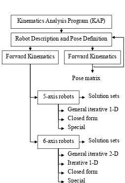
Kinematics Analysis Program is a program developed by Rachid Manseur [2]. KAP is currently developed to compute the forward and inverse kinematics of robot manipulators with 5 or 6 revolute degrees of freedom. The functional block diagram of KAP is shown on Figure 2.3. There are two type of KAP:
i. KAP5 – to compute the inverse kinematics problem for 5 DOF of Rhino XR-3 robot (See Figure 2.2).
Figure 2.2: GUI of KAP5.
Table 2.1: Robot DH-parameter table
Link d a
1 d1 a1 1 1
2 d2 a2 2 2
3 d3 a3 3 3
4 d4 a4 4 4
5 d5 a5 5 5
Figure 2.3: Functional Block Diagram of KAP Kinematics Analysis Program (KAP)
Robot Description and Pose Definition
Forward Kinematics Forward Kinematics
5-axis robots
6-axis robots
Solution sets
Solution sets General iterative 1-D Closed form
Special Pose matrix
General iterative 2-D
[image:21.595.193.446.276.646.2]The forward kinematics problem is concerned with the relationship between the individual joints of the robot manipulator and the position and orientation of the tool or end-effector. Stated more formally, the forward kinematics problem is to determine the position and orientation of the end-effector, given the values for the joint variables of the robot [5].
In order to describe the location of each link relatives to its neighbors we define a frame attached to each link. The link frames are named by number according to the link to which they are attached. That is, frame {i} is attached rigidly to linki.
To locate frames on the links, this convention is used: The Z-axis of frame {i},
called Zi is coincident with the joint axisi. The origin of frame {i} is located where i
a perpendicular intersects the joint iaxis. Xi points along aiin the direction from
joint ito joint i1 [1].
In the usual case of revolute joint, i is called the joint variable, and the other
three quantities would be fixed link parameters. For prismatic joints, di is the joint
2.4.1 Denavit Hartenberg Representation
Figure 2.4: Link Parameter.
A commonly used convention for selecting frames of reference in robotic applications is the Denavit-Hartenberg, or DH convention. In this convention, each homogeneous transformation Ai is represented as a product of four basic
transformations. The procedure based on the DH convention in the following algorithm for deriving the forward kinematics for any manipulator are summarize as below [5]:
Step l : Locate and label the joint axesz0,....,zn1.
Step 2 : Establish the base frame. Set the origin anywhere on the z0-axis. The x0
and y0 axes are chosen conveniently to form a right-hand frame. For
1,...., 1
i n , perform Steps 3 to 5.
Step 3 : Locate the origin Oi where the common normal to zi and zi1 intersectszi.
If zi intersects zi1 locate Oi at this intersection. If zi and zi1 are parallel,
locate Oi in any convenient position alongzi.
Step 4: Establish xi along the common normal between zi1 and zi through Oi, or in
set zn a along the directionzn1. Establish the origin on conveniently along n
z , preferably at the center of the gripper or at the tip of any tool that the
manipulator may be carrying. Set yn s in the direction of the gripper
closure and set xn n ass a . If the tool is not a simple gripper set xnand
n
y conveniently to form a right-hand frame.
Step 7 : Create a table of link parametersai,di,i,i. i
a Distance along xi from oi to the intersection of the xi and zi1axes. i
d Distance along zi1 from Oi1 to the intersection of the xi and zi1axes. i
d is variable if joint i is prismatic. i
The angle between zi1 and zi measured about xi(see Figure 2.4).
i
The angle between xi1 and xi measured about zi1 (see Figure 2.4). i
is variable if joint i is revolute.
Step 8 : Form the homogeneous transformation matrices Ai by substituting the
above parameters into equation 2.1. Step 9 : Form 0
1....
n n
T A A. This then gives the position and orientation of the tool
frame expressed in base coordinates.
The overall transformation is obtained by post multiplication of individual transformations:
1 ( , ) (0,0, ) (0,0, ) ( , )
i
i i i i i
T Rot z Trans d Trans a Rot x (2.1)
1
0 0 1 0 0 0 1 0 0 1 0 0 0
0 0 0 1 0 0 0 1 0 0 0 0
0 0 1 0 0 0 1 0 0 1 0 0 0
0 0 0 1 0 0 0 1 0 0 0 1 0 0 0 1
i i i
i i i i
i i
i i i
c s a
s c c s
T
d s c