FORWARD KINEMATICS SOLUTION: VISUALIZATION OF
RHINO XR-3 ROBOT FOR 5 DEGREE OF FREEDOM
Mohd Khairul Faizie Bin Tarmudi
Bachelor of Mechatronic Engineering
“I hereby declare that I have read through this report entitle “Forward Kinematics Solution: Visualization of Rhino XR-3 Robot for Five Degree of Freedom” and found that it has comply the partial fulfillment for awarding the degree of Bachelor of Mechatronics Engineering”
Signature : ……….
Supervisor‟s Name : ……….
FORWARD KINEMATICS SOLUTION: VISUALIZATION OF RHINO XR-3 ROBOT
FOR FIVE DEGREE OF FREEDOM
MOHD KHAIRUL FAIZIE BIN TARMUDI
A report submitted in partial fulfillment of the requirements for the degree of Bachelor
of Mechatronics Engineering
Faculty of Electrical Engineering
UNIVERSITI TEKNIKAL MALAYSIA MELAKA
I declare that this report entitle “Forward Kinematics Solution: Visualization of Rhino XR-3 Robot for Five Degree of Freedom” is the result of my own research except as cited in the references. The report has not been accepted for any degree and is not concurrently submitted in candidature of any other degree.
Signature : ...
Name : ...
ACKNOWLEDGEMENT
Alhamdulillah, after all the research and work that I have done, I have finished my
Final Year Project (FYP). First of all I would like to express profound gratitude to my project
supervisor, Mrs. Irma Wani Binti Jamaludin for her invaluable support, encouragement,
suggestion and advice through my FYP project. Her moral support and guidance has enabled
me to complete my project successfully.
Thank you my panel, Mr Herman Bin Jamaluddin and Mr. Razali Bin Mohamad
Sapiee because of their suggestion and comment during presentation of my project on the first
seminar. I would like to thanks to my family because understand my responsibility as a student
and the moral support that has given to me.
I also want to thank to my 4th year friends of Bachelor of Mechatronic Engineering
(BEKM) especially to my friend that under the same supervisor as me because of their
helping, sharing information, team work and cooperation given to accomplish this project
successfully.
Lastly, I would like to thank to all that has help me from the very beginning to the end
ABSTRACT
This project is basically to develop software that will calculate the forward kinematics solution
and visualize the final position of the Rhino XR-3 Robot with 5 degree of freedom (DOF).
Initially, an algorithm is being developed to solve the forward kinematics problem. In order to
know the final position of the robot, in this case the position of the gripper, the parameters of
the robot needs to be applied. The parameters for this robot are the angle of rotation of the
linkage between the arms of the robot and also the length between the joint. The final position
of the robot can be obtained manually using conventional method. For this project, a software
will be develop to solve the calculation faster than manual calculation and to review the final
position of the robot. Both results obtain using the developed software and conventional
method will be compared to make sure that the software can be used to solve the forward
kinematics problem. The interface of the software needed user to insert desire value of Theta (θ) and the final position of the robot will be displayed. The visual aided in the interface will
help user to know the exact position of the robot. Throughout this project, the method to solve
the forward kinematics problem will be shown from developing the algorithm until the
ABSTRAK
Secara asasnya projek ini membangunkan perisian komputer yang akan menyelesaikan
gerakan kinematik hadapan dan memaparkan kedudukan akhir robot Rhino XR-3.
Pertamanya, satu algoritma dibuat untuk menyelesaikan permasalahan kinematik hadapan.
Permasalahan kinematik hadapan ini diselesaikan untuk menentukan kedudukan dan
pergerakan cekam dengan menggunakan perisian yang sesuai untuk robot Rhino XR-3. Proses
yang terlibat ialah kawalan terhadap parameter iaitu sudut putaran bagi 3 paksi dan panjang
antara titik paksi lengan robot. Permasalahan kinematik hadapan boleh diselesaikan dengan
menggunakan kaedah konvensional dan secara manual. Untuk projek ini, satu perisian
komputer telah dibangunkan untuk menyelesaikan perkiraan kinematik hadapan lebih cepat
berbanding kiraan biasa dan kedudukan akhir robot akan ditunjukkan. Hasil kiraan
menggunakan perisian yang dibuat akan dibandingkan dengan kiraan secara manual bagi
memastikan perisian tersebut dapat digunakan untuk menyelesaikan masalah kinematik
hadapan. Pengguna akan memasukkan nilai theta (θ) pada paparan muka perisian tersebut dan seterusnya kedudukan akhir robot akan dipaparkan. Dengan ini, pengguna akan mengetahui
kedudukan sebenar robot dari nilai sudut yang dikehendaki mereka. Secara keseluruhannya,
projek ini menerangkan bermula dari teknik, cara pengiraan dan kaedah penyelesaian
TABLE OF CONTENT
CHAPTER CONTENT PAGE
ACKNOWLEDGEMENT v
ABSTRACT vi
TABLE OF CONTENTS viii
LIST OF TABLES x
LIST OF FIGURES xi
LIST OF ABBREVIATIONS xii
LIST OF APPENDICES xiii
1 INTRODUCTION 1
1.1 Background 1
1.2 Problem Statement 2
1.3 Objective 3
1.4 Scope 4
2 LITERATURE REVIEW 5
2.1 SIRF-Rhino (RhinoGUI) 5
2.2 RHINO XR-3 Robot 7
2.3 Denavit-Hartenberg (DH) Representation 8
2.4 Kinematics Analysis Program (KAP) 11
2.5 Forward Kinematics of Rhino XR-3 Robot 13
2.6 Microsoft Visual Basic 6.0 15
2.7 Solidwork 2007 16
3 METHODOLOGY 17
3.1 Overview 17
CHAPTER CONTENT PAGE
3.3 Software 19
3.4 Designing Graphical User Interface with
Corresponding Command 20
3.4.1 DH Parameters Table 21
3.4.2 Final Transformation Matrix 22
3.4.3 Theta Value 23
3.4.4 Final Position 23
3.4.5 Limitation Value 24
3.5 Rhino XR-3 Robot 3D Modeling 26
4 RESULT AND ANALYSIS 28
4.1 Overview 28
4.2 Rhino Forward Features 29
4.3 Using Rhino Forward Software 30
4.4 Microsoft Visual Basic Programming Command
for Rhino Forward 32
4.5 Rhino Forward Analysis 43
4.6 Rhino XR-3 Robot Design 46
4.7 Discussion 47
5 SUMMARY AND CONCLUSION 49
5.1 Summary 49
5.2 Conclusion 49
5.3 Recommendation 50
LIST OF TABLES
TABLE TITLE PAGE
2.1 Robot DH parameter table. 13
LIST OF FIGURES
FIGURE TITLE PAGE
2.1 The RhinoGui interface. 6
2.2 Rhino XR-3 Robot 7
2.3 Denavit Hartenberg Frame Assignment 8
2.4 Functional Block Diagram of KAP 12
2.5 The Specification of the Rhino XR-3 Robot 13
2.6 Example of GUI 15
2.7 Solidwork Interface with 3D drawing example. 16
3.1 Process flow of the project methodology 18
3.2 The tools option. 21
3.3 Frame for DH Parameter Table 22
3.4 Final Transformation Matrix Frame 22
3.5 Theta Value Frame 23
3.6 Final Position and „Calculate‟ Button. 24
3.7 Error Occur Indicate the Wrong Value of Theta 24
3.8 3D Model of Rhino XR-3 Robot 27
4.1 GUI of Rhino Forward. 29
4.2 Final position with Theta = 10°. 31 4.3 Error when an alphabet is inserted as theta. 43
4.4 The limitation value for θ1 44
LIST OF ABBREVIATIONS
DH - Denavit Hartenberg
DK - Direct Kinematics
DOF - Degree of Freedom
GUI - Graphical User Interface
LIST OF APPENDICES
NO. TITLE PAGE
Appendix 1 Project Planning 54
Appendix 2 Specification of Rhino XR-3 robot 56
Appendix 3 Rhino Forward Command in Microsoft Visual Basic 58
CHAPTER 1
INTRODUCTION
The project entitle “Forward Kinematics Solution: Visualization of Rhino XR-3 Robot for 5 Degree of freedom” is a project to solve the forward kinematics problem and to visualize the final position of the Rhino XR-3 Robot. To achieve this goal, a software is developed to
design a graphical user interface (GUI) with visualization of the final position of the robot.
The first chapter will discuss the objective of the project, scope and the problem statement for
this project.
1.1 Background
Kinematics is the science of motion which treats motion without regard to the forces
that cause it [1]. In this project, forward kinematics concept was applied where Keith Peters
stated that, Forward Kinematics (FK) deals with motion that originates at the base of the
Kinematics problem can be solved using conventional method where this method has a
long calculation and a complex equation. This method was used for educational purpose all
around the world. However, this method is not practical in industrial sector as the development
of robotic sector and the complexity of the modern robot. The degree of freedom (DOF) of the
robot will affect the calculation process. It takes a longer time to solve the problem if the robot
has higher DOF. This project used Rhino XR-3 robot where it has 5 DOF.
Using a programming or software to solve the forward kinematics problem is well
accepted nowadays as users can solved the problem in no time. For this project, a graphical
user interface (GUI) for Rhino XR-3 robot will be develop with the visualization of the robot
to show the final position of the robot.
1.2 Problem Statement
In industrial sector especially involved robotic application, there were several methods
to solve the forward kinematics solution by using conventional method or using software.
Usually user will used the conventional method to solve the forward kinematics problem. The
complexity of formulation and computational burden make this method hard to be
implemented in practice which also will waste a lot of time [10]. This method is a complex
calculation that needs precision when working on kinematics solution. So, the more DOF is
implemented, the longer and more complex the calculation would be.
It is also take a long time working on the forward kinematics solution using
conventional method. As in industry and production sector, time is the most considerable thing
of profit. The time taken solving the kinematics problem is increase with increasing the DOF
Therefore, a new method to solve the kinematics problem especially the forward
kinematics was created. Programming software was developed to calculate and solve this
kinematics problem easier. The complexity of the calculation process and the time taken to
solve the kinematics problem can be minimized. In addition to this software, it will show the
final position of the robot in three dimensional (3D) views. This visualization will help user to
know exactly the final position of the robot, from the origin.
1.3 Objective
The objectives of this project are to solve the forward kinematics problem and to
visualize the final position of the Rhino XR-3 robot. The algorithm will be developed and
tested with manual calculation before a software for the GUI is developed. The more specified
objectives of this project are;
a) To solve the forward kinematics solution manually.
b) To develop an algorithm for forward kinematics solution.
c) To develop the GUI for forward kinematics solution using Visual Basic
software.
d) To visualize the final position of the Rhino XR-3 robot using Solidwork
1.4 Scope
The scope of this project is to develop the programming software or GUI to solve the
forward kinematics problem, only for Rhino XR-3 robot with 5 DOF. It cannot be applied to
other robot model unless a modification was made to the software. The software will be
develop based on the algorithm constructed that specified for 5 DOF. In this project, the
software choose to develop the GUI is Visual Basic software.
The visualization of the robot will be in 3D view. The program will only view the
Rhino XR-3 robot. The Solidwork software has been chosen to develop the 3D view. The
CHAPTER 2
LITERATURE REVIEW
In this chapter, a review of previous research project that are related with this project
will be discussed. The review will include the previous research and studying in forward
kinematic concept. The concept is including the D-H parameters and Rhino XR-3 Robot.
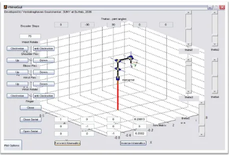
2.1 SIRF-Rhino (RhinoGUI)
The SIRF-Rhino is the example of Graphical User Interface (GUI) for Rhino XR-3
robot. This interface was developed by Venkatraghavan Gourishankar that applied the Rhino
XR-3 robot to study the kinematics of the robot itself and to teach the beginner in robotics [3].
This GUI was able to perform kinematics routine and control the rhino robot in real time. This
program was divided into two sections, RhinoGui and RhinoWhite. RhinoGui was designed
such that the user can get a feel for kinematics of the 5-axis articulated Rhino robot while
RhinoWhite was developed for demonstrating the basic trajectory planning method for the
Figure 2.1 shows the interface of the RhinoGui. To use the forward kinematics option, simply choose the „forward kinematics‟ button at the bottom of the interface. The plot of the robot configuration will change and the arm matrix configuration will change according to
configuration setting by the user. The initial value of the joint angles represent by theta (θ)
[image:20.612.83.540.262.573.2]where the angle for each theta in degreewas; θ1= 0°, θ2 = -90°, θ3 = 90°, θ4 = 0°, andθ5 = 0°. These values represent the home position of the Rhino XR-3 robot.
Since this program was developed through MATLAB, it can be used for all students in
university, college and some high school to learn about kinematics especially forward
kinematics. This program has user friendly interface that help new user and wanted to learn
about robotic movement and kinematics.
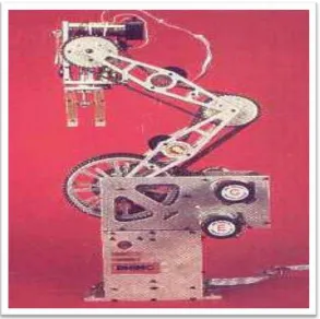
2.2 RHINO XR-3 Robot
Rhino XR-3 robot is constructed out of 0.125 inch and 0.250 inch thick aluminum
plate for years of trouble free service. It is powered by six PMDC servo motors with integral
gearboxes and incremental encoders. The home position has microswitches on all axes and on
the hand. It is easy to service and repair construction throughout. It is also a popular design
[image:21.612.185.478.402.694.2]with installations throughout the world [4].
Figure 2.2 show the example of Rhino XR-3 robot. This robot has used widely for
educational purpose. It is easy to control as is have five DOF. This robot has simple design
and user can easily determined the connection and joint between the connection points. This
robot has electrical gripper at the end joint and has been classified as arm robot.
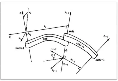
2.3 Denavit-Hartenberg (DH) Representation
Denavit-Hartenberg (DH) convention was introduced by Jaques Denavit and Richard
S. Hartenberg [7]. It is a commonly used convention for selecting frames of reference in
robotic applications. In this convention, each homogeneous transformation Aiis represented as
a product of four basic transformations. Figure 2.3 show the example of Denavit Hartenberg
[image:22.612.117.516.410.685.2]assign frame.
There were procedures based on the DH convention in the following algorithm for
deriving the forward kinematics for any manipulator summarized below [5]:
Step l : Locate and label the joint axesz0,....,zn 1.
Step 2 : Establish the base frame. Set the origin anywhere on the z0-axis. The x0 a
y0 axes are chosen conveniently to form a right-hand frame. For i 1,....,n 1
perform Steps 3 to 5.
Step 3 : Locate the origin Oi where the common normal to zi and zi 1 intersectszi If
zi intersects zi 1 locate Oi at this intersection. If zi and zi 1 are parallel,
locate Oi in any convenient position alongzi.
Step 4 : Establish xi along the common normal between zi 1 and zi through Oii,
or in the direction normal to the zi 1 zi plane if zi 1 and zi intersect.
Step 5 : Establish yi to complete a right-hand frame.
Step 6 : Establish the end-effector frame o x y zn n n n. Assuming the n-th joint is
revolute set zn a along the directionzn 1. Establish the origin on
conveniently alongzn, preferably at the center of the gripper or at the tip of
any tool that the manipulator may be carrying. Set yn s in the direction of
the gripper closure and set xn n ass a. If the tool is not a simple gripper
Step 7 : Create a table of link parametersai,di, i, i.
ai Distance along xi from oi to the intersection of the xi and zi 1axes.
di Distance along zi 1 from Oi 1 to the intersection of the xi and zi 1axes
di is variable if joint i is prismatic.
i The angle between zi 1 and zi measured about xi(see Figure 2.3).
i The angle between xi 1 and xi measured about zi 1 (see Figure 2.3). i is
variable if joint i is revolute.
Step 8 : Form the homogeneous transformation matrices Ai by substituting the above
parameters into equation 2.1.
Step 9 : Form 0
1....
n n
T A A . This then gives the position and orientation of the tool
frame expressed in base coordinates.
The overall transformation is obtained by post multiplication of individual
transformations:
Ti
i+ 1 = Rot (z, θ
i) Trans(0,0,di) Trans(0,0,ai) Rot(x,αi) (2.1)