UNIVERSITI TEKNIKAL MALAYSIA MELAKA
DEVELOPMENT OF AN AUTOMATED KEROPOK LEKOR
CUTTING MACHINE USING PNEUMATIC SYSTEM
This report submitted in accordance with requirement of the Universiti Teknikal Malaysia Melaka (UTeM) for the Bachelor Degree of Manufacturing Engineering
(Robotic and Automation) with Honours.
by
MOHD ADIB BIN TUKIRAN
DECLARATION
I, hereby, declared this report entitled “Development of an automated keropok lekor cutting machine using pneumatic system” is the result of my own research except as
cited references.
Signature : ………..
Author’s Name : MOHD ADIB BIN TUKIRAN
APPROVAL
This report is submitted to the Faculty of Manufacturing Engineering of UTeM as partial fulfillments for the degree of Bachelor of Manufacturing Engineering (Robotic and Automation) with Honours. The member of supervisory committee is as follow:
……….. (ISMAIL BIN ABU SHAH)
Main Supervisor
ABSTRACT
ABSTRAK
DEDICATION
For my beloved parents:
Hj. Tukiran @ Maskuri bin Hj. Nor @ Md. Ali Hjh. Jumirah @ Fauziah binti Hj. Yassin
For my cherish brothers and sisters:
Mohd Latif bin Tukiran M. Tusidan bin Tukiran Hj. Mohd Rohimi bin Tukiran
Siti Katiah binti Tukiran Siti Norisnaini binti Tukiran
For my beloved fiancée
Rabiatul Adawiyah binti Hj. Ismail
And my treasured friends
ACKNOWLEDGEMENT
In The Name of Allah; the Most Gracious and the Most Merciful, Be Upon His Messenger Prophet Muhammad S.A.W and His Companions.
Assalamualaikum W.B.T.,
First of all, thanks to Allah for his divine inspirational guidance, this helped me to accomplish this project. I would like to convey my sincere thanks to project supervisor, Mr. Ismail bin Abu Shah for his constructive guidance and patience in fulfilling our inspiration in completing this project.
Besides, special thanks to the Microzas Sdn. Bhd. and Mr. Hazreen Azeez bin Abdul Rahman for their explanation, demonstration, and providing facilities in order to develop the machine prototype. Finally, I would like to express greatest gratitude to my family and friends for their valuable encouragement and continuous support until the completion of this study.
Last but not least, I would like to convey special thanks to those person who had contributed to my final year project, whether directly or indirectly.
Sincerely,
3.3.3 Automated System 17
3.4 Keropok Lekor Properties 19
3.5 Cutting Mechanism 20
3.5.1 Important Criteria of Cutting Mechanism 22
3.6 Electric Motor 25
3.6.1 AC Motors 27
3.6.2 DC Motors 29
3.6.3 Stepper Motors 30
2.7 Relay Logic 31
2.7.1 Basic Format for Relay Logic Diagram 33
2.8 Pneumatic System 34
2.8.1 Advantages of Pneumatic Systems 35
2.8.2 Pneumatic Components 36
2.8.2.1 Actuator 36
2.11.1 Steps to Develop Pugh Method 45
2.12 Push Pull Gauge 46
4.0 METHODOLOGY 48
4.1 Stages of The Project 48
4.1.1 Project Understanding and Planning 49
4.1.2 Define Specification 51
4.1.3.1Books 52
4.1.3.2Journals, Articles, and Paper 52
4.1.3.3Catalogues 52
4.1.3.4Internet Resources 52
4.1.4 Conceptual Design 53
4.1.5 Detail Design and 3D Modeling 54
4.1.6 Design Optimization 55
4.1.7 Fabrication and Assembly 56
4.1.8 Testing 57
4.1.9 Discussion 58
4.1.10 Conclusion 58
4.1.11 Presentation and Evaluation 58
4.0 RESULT AND ANALYSIS 59
4.1 Identification of Customer Requirement 60
4.2 Define Product Specification 64
4.2.1 Experimental Analysis 65
4.3 Design Concept Generation 68
4.3.1 Concept 1: Cam-Follower Mechanism 69
4.3.2 Concept 2: Pneumatic System 70
4.5.1.1 Specification of Pneumatic Cylinder 77
4.6.2 Drive and Driven System 91
4.6.3 System Operation 92
4.6.4 Design Optimization 95
4.6.4.1 Cutter Blade 96
4.7 Fabrication 97 4.7.1 Bending 97 4.7.2 Welding 98 4.7.3 Turning 99 4.7.4 Milling 100
4.8 Machine testing 101
4.8.1 Testing result 101
5.0 DISCUSSION 104
5.1 Normal Cutting Process 105
5.2 Main Factor of Machine Performance 108
5.3 Degree of Freedom in Keropok Lekor Cutting Process 107
5.4 Techniques to Implement Cutting Process 112
5.5 Proposal of Machine Improvement 120
6.0 CONCLUSION AND SUGGESTIONS 123
6.1 Conclusion 123
6.2 Suggestions 124
LIST OF TABLES
1.1.1 Gantt Chart for PSM 1 7
1.1.2 Gantt Chart for PSM 2 8
LIST OF FIGURES
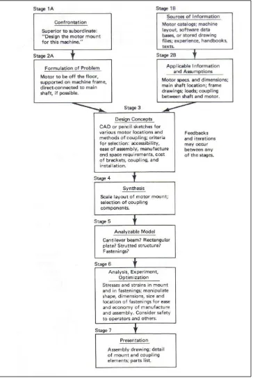
2.1 The Seven Stages of Engineering Design 11
2.2 Product Development Path 14
2.3 Manual Work System 16
2.4 Workers-Machine System 17
2.5 Automated Systems 18
2.6 Keropok Lekor Structure 20
2.7 Manual Cutting of Keropok Lekor 21
2.8 Example of Forces in Equilibrium 23
2.9 Force applied and force exerted during cutting keropok lekor 23
2.10: A real cut notch in cutting process 24
2.11: Types of electric motor 26
2.12 Symbols for common relay logic diagram 31
2.13: An example for relay logic diagram 33
3.2 Design optimization using CosmosXpress 56
4.1 The eight stages of chapter 4 60
4.2 HOQ for this project 62
4.3 Experimental analysis of keropok lekor manual cutting 66
4.4 The keropok lekor has been cut 66
4.5 Cutting keropok lekor in various measurements 67
4.6 Cam and follower cutting mechanism 69
4.7 Pneumatic cutting system 70
4.8 Worm gear concept 71
4.9 Rack and pinion mechanism 72
4.10 Cylinder bore 76
4.11 Pneumatic cylinder from SMC 77
4.13 Cutting mechanism 87
4.14 Feeding mechanism 89
4.15 Complete design of keropok lekor cutting machine 90
4.16 Drive and driven system 91
4.17 Operation of the system 92
4.18 The electrical circuit for keropok lekor cutting machine 95
4.19 Cutter blade 96
4.20 Conveyor frame which produced using bending process 98
4.21 Supported leg of the machine 99
4.22 Drive shaft of the machine 100
4.23 Supporting plate been produced using face milling process 100 4.24 Result of keropok lekor cutting process 102
4.25: Keropok lekor cut manually 103
4.26: Keropok lekor cut using machine 103
5.1: Manual cutting of keropok lekor 105
5.2: Keropok lekor cutting machine (front view) 106 5.3: Repeated applied and exerted force caused keropok lekor to twist 108
5.4 The twelve degree of freedom 109
LIST OF ABBREVIATIONS
3D 3 Dimension
ABET Accreditation Board for Engineering and Technology
AC Alternating Current
ADAMS Automated Dynamic Analysis of Mechanical System
CAD Computer Aided Design
DC Direct Current
HOQ House of Quality
MOA Memorandum of Agreement
PDI Product Development Institute
PDMA Product Development and Management Association
PSM Projek Sarjana Muda
QFD Quality Function Deployment
RPM Rotation per Minute
TPG Taiwan Precision Gear
SMI Small and Medium Industry
CHAPTER 1
INTRODUCTION
The research entitled “Development of an Automated Keropok Lekor Cutting Machine Using Pneumatic System”. Generally this chapter provides information about background, problem statement, objectives and scopes of the study. Besides that, outline of this study also included in this chapter.
1.1 Project Background
Nowadays, Small and Medium Industry sector (SMI) have been expanded widely and play an important role in generating Malaysian economy. SMI products have been spread widely and become popular rather than well-known imported product. Previously, foods like nugget, burger, frankfurter, and fish ball are imported or very hard to find in the market but currently can be easily found. The development of SMI has influenced many local foods such as keropok lekor, otak-otak, and many confectionary products to be commercialized. Therefore, SMI entrepreneurs need a machine to increase their productivity in order to fulfill market requirement. Unfortunately, special machine to automate the process in SMI still not widely discovered.
1.1.1. Keropok Lekor
Keropok lekor is a famous snack food which is originated from East-Coast of Malaysia Peninsular. It is a speciality of Terengganu and now has been widely commercialized to entire country. Generally, keropok can be categorized as a type of snack which is made of flavored with fish or shrimp. The mixture is being hand-rolled into a sausage form. Ingredients of the mixture are fish (mackerel), sago flour, salt, water, ice cubes, and pandan leaves.
There are two methods to eat keropok lekor which are eat freshly after it has been boiled or by deep frying it. Usually, the huge and long sausages are cut into smaller pieces and thrown into the pan to be deep-fried until they turn crispy gold. Another option to take keropok lekor is to just steam it. This gives it a fishier flavor but tastes as good as the crispy ones according to some people. A completely different kind of keropok is keropok keping and it comes in different flavors: fish, squid, and prawn. Here, the keropok is shaped into even bigger tubes and cut into thin slices to let it dry in the sun. Keropok lekor ready to be served with their chili sauce, or with own home-made chili sauce if one prefers or shrimp-based sauce is also common. The best way to eat the keropok lekor is by take it right after frying when it is still hot, crispy on the outside and tender at the inside.
1.1.2. Cutting System
Theoretically, cutting process is a combination of compressive and shearing phenomenon. It will only occur when the total stress generated by the cutting implement exceeds the ultimate strength of the material of the object being cut. The simplest applicable equation is stress = force/area. In the cutting process, the forces will acts on a body; there is an accompanying change in shape or size of the body (keropok lekor). Here, can be assumed that the stress generated by a cutting implement is directly proportional to the force which it is applied, and inversely proportional to the area of contact. Hence, the less force is needed when cutting small area, higher force is needed when cutting higher surface area.
1.2 Problem Statement
Keropok lekor, a popular fish based snack, is usually molded from kneaded fish meat and dough. Usually keropok lekor prepared using traditional methods with some mechanical equipment such as horizontal mixer and horizontal mince to knead the fish meat. Meanwhile degutting and deboning of the fresh fish is done manually. The job to roll the kneaded fish meat and boil is also done manually. More, keropok lekor itself should be cut into smaller size before being fry and this job also done manually because no proper machine has been created. The high requirements of keropok lekor in the market urge entrepreneurs to increase their production but they facing a lot of problem to fulfill market requirement.
Nowadays, invention of machine that would cut keropok lekor to small pieces or specific size still not widely discovered in Malaysia. Thus, the invention of keropok lekor cutter machine should be done to help the keropok lekor entrepreneurs to automate cutting process. As a consequence, their volume production will increase and the product itself can be commercialized and exported to worldwide.
1.3 Objectives
The objectives of this study are:
(a) To design pneumatic system for cutting mechanism.
(b) To develop an automated cutting machine for keropok lekor entrepreneur.
1.4 Scopes of This Project
In order to meet the objectives listed, the scopes of this project have been defined. There are:
(a) To design an automated keropok lekor cutting machine using SolidWorks 2007 software.
(b) To define value of force applied using push pull gage.
(c) To optimize design of the keropok lekor cutter using COSMOXpress.
1.5 Benefits of The Project
There are a few benefits of this project either directly or just influenced by this new invention. The benefits are: procedure and write a thesis in correct format.
(c) The company can adapt and commercialized the research and innovation has been done by university academician via memorandum of agreement (MOA).
1.6 Project Planning
The project report should be arranged systematically in order to convey better understanding entire of the study. So that, an outline of the project has been constructed to briefly explain and summarize the content of every chapter. Overall of this study are divided into six chapters. They are:
(a) Chapter 1: Introduction
This chapter covers the background of the project, problem statement, objectives and scope of the study. In addition, the benefits and the outlines of the project are included here.
(b) Chapter 2: Literature Review
(c) Chapter 3: Methodology
This chapter includes flowchart which cover overall stage involve of this study. Then, every stage in the flowchart is explained briefly, covering PSM 1 and PSM 2.
(d) Chapter 4: Results & Analysis
This chapter covers the analysis of the study. The result consist of customer requirements which have been simplified in the house of quality, selection of conceptual design using Pugh Method, detail design, and 3D modeling of the machines as well as the he finish product. Besides, a few analysis will be conduct here as a supporting details of related data in order to develop this machine. The analysis consists of theory and experiment, so that the machines develop will be firmly fulfill the criteria and standard restricted.
(e) Chapter 5: Discussion
This chapter discussed the data analysis based on the result obtain in previous 4. Firstly, discussion will be focused on the simulation of the pneumatic cutting system, and then the discussion is about the performance of the machine that will be developed whether it success or not. A critical discussion should will de done here to reveal the key factor of success or failure of this project.
(f) Chapter 6: Conclusion
Generally, this chapter concludes the main findings of the study. Recommendation for further study which related to the development of automated keropok lekor cutting machine also will be included in this chapter.
CHAPTER 2
LITERATURE REWIEW
This chapter briefly explains about the definition and information of design, automated, cutting mechanism, motor, keropok lekor characteristics, pneumatic system and software; their scope, features, and relationship among them in implementation of this project. Besides, a few techniques which are related with the invention such as Pugh Method and House of Quality (HOQ) also will be explained at this chapter. Generally, this chapter focused on a single question which tries to identify, appraise, select and synthesize all high quality research evidence relevant to this project
2.1 Design
2.1.1 Engineering Design
Engineering design is the systematic, intelligent generation and evaluation of specifications for artifacts whose form and function achieve stated objectives and satisfy specified constraints (Dym and Lewit, 1991). Besides, engineering design has been defined as the process of applying the various techniques and scientific principles for the purpose of defining a device, a process or a system in sufficient detail to permit realization (Norton, 1999). He also stated that design may be simple or enormously complex, easy or difficult, mathematical or nonmathematical which may involve a trivial problem or one of the great importances.
Meanwhile, according to Madara & Kremer (2004), engineering design is the application of technical knowledge with knowledge of from non-technical disciplines and the use of design and analysis tools to synthesize a product or system that solves a particular problem or meet a specific need. Both academicians also agreed with the statement of The US Accreditation Board for Engineering and Technology (ABET, 1995) which identifies engineering design as the process of deriving a system, component, or process to meet desired need. It is a decision making process (often iterative), in which the basic sciences, mathematics, and engineering sciences are applied to convert resources optimally to meet a stated objective. Among the fundamental elements of design process are the establishment of the objectives and criteria, synthesis and analysis, construction, testing and evaluation. Further, engineering design is entailed to include a variety of constrains such as economic factors, safety and reliability, aesthetics, ethics and social impacts.
Then, design concepts listed in third stage. Stage four is synthesis while fifth is analyzable model. Analysis, experiment, and optimization located at stage six, while presentation listed at the last stage. The seven stage of engineering design produced by Erdman and his colleagues is such in Figure 2.1 below.