UNIVERSITI TEKNIKAL MALAYSIA MELAKA
Design and Development of Grass Cutting
Machine using DFMA Methodology
Thesis submitted in accordance with the requirements of Universiti Teknikal
Malaysia Melaka for the Bachelor’s degree in Manufacturing Engineering (Manufacturing Design) with Honours
By
MOHD ISHAMMUDIN BIN MOHD YUNUS
Faculty of Manufacturing Engineering
UTeM Library (Pind.1/2007)
SULIT
TERHAD
TIDAK TERHAD
(Mengandungi maklumat yang berdarjah keselamatan atau kepentingan Malaysia yang termaktub di dalam AKTA RAHSIA RASMI 1972)
(Mengandungi maklumat TERHAD yang telah ditentukan oleh organisasi/badan di mana penyelidikan dijalankan)
(TANDATANGAN PENULIS)
Alamat Tetap:
NO 453,Jln Hj Adnan, Kg Gching, 43900,Sepang, Selangor Darul Ehsan
Saya _____________________________________________________________________
mengaku membenarkan tesis (PSM/Sarjana/Doktor Falsafah) ini disimpan di Perpustakaan Universiti Teknikal Malaysia Melaka (UTeM) dengan syarat-syarat kegunaan seperti berikut:
1. Tesis adalah hak milik Universiti Teknikal Malaysia Melaka.
2. Perpustakaan Universiti Teknikal Malaysia Melaka dibenarkan membuat salinan untuk tujuan pengajian sahaja.
3. Perpustakaan dibenarkan membuat salinan tesis ini sebagai bahan pertukaran antara institusi pengajian tinggi.
4. **Sila tandakan (√)
Design and Development of Grass Cutting Machine using DFMA Methodology
2007/2008
MOHD ISHAMMUDIN BIN MOHD YUNUS
(TANDATANGAN PENYELIA)
Cop Rasmi:
DECLARATION
I hereby, declare this thesis entitled “Design and Development of Grass Cutting Machine
using DFMA Methodology” is the results of my own research
except as cited in the reference.
Signature : ……..……….
Author’s Name : ………
Date : ………
APPROVAL
This thesis submitted to the senate of UTeM and has been accepted as fulfillment of the
requirement for the degree of Bachelor of Engineering Manufacturing (Design). The
members of the supervisory committee are as follows:
………
Main supervisor
ABSTRACT
This project describes about the implementation of redesign the grass cutting machine by
using the application of Design for Manufacturing and Assembly (DFMA) methodology.
The scope based on the existing grass cutting machine and the appropriate of DFMA
methodology. The method used for gaining the data is from the reassembled the existing
grass cutting machine. From the data achieved, it can be classified into several categories
to be studied. Data will be analyzed by using Lucas Hull method to verify the design
efficiency, handling ratio and fitting ratio to achieve. The tools that used is TeamSET
software. The new proposed design of grass cutting machine drawn using SolidWorks
software based on TeamSET result achieved. Result shown that the design efficiency for
redesign grass cutting machine obtained better percentage rather than the existing design.
From the study, the total part, handling ratio fitting ratio and cost of existing design is
reduced. Eventually, the improvement of redesign grass cutting machine finally will be
ABSTRAK
Kertas kerja ini menghuraikan tentant perlaksanaan dalam mereka bentuk semula mesin
pemotong rumput dengan menggunakan aplikasi DFMA (Design for Manufacturing and
Assembly). Skop projek adalah memfokus kepada rekabentuk asal mesin pemotong
rumput dan disertakan dengan aplikasi DFMA. Kaedah yang digunakan untuk
mendapatkan data adalah daripada memasang semula mesin pemotong rumput. Hasil data
yang diperolehi akan dikelaskan kepada beberapa kategori sebelum analisa dilakukan.
Kemudian, kesemua data tersebut akan dianalisa dengan menggunakan kaedah Lucas
Hull untuk menentukan kecekapan rekabentuk, nisbah pengendalian, nisbah perhimpunan
sebagai pencapaian objektif projek. Perkakasan yang terlibat adalah perisian TeamSET.
Rekabentuk mesin pemotong rumput yang baru akan di lukis menggunakan perisian
SolidWorks berdasrkan keputusan yang dicapai daripada perisian TeamSET. Keputusan
menunjukkan bahawa kecekapan reka bentuk untuk rekabentuk semula mesin pemotong
rumput memperolehi peratusan lebih baik daripada rekabentuk yang asal. Daripada
kajian, bahagian terjumlah, nisbah pengendalian, nisbah perhimpunan dan kos telah
dikurangkan. Akhirnya, peningkatan rekabentuk semula mesin pemotong rumput
DEDICATION
ACKNOWLEDGEMENTS
First and foremost, I would like to express my highest appreciation to my supportive
academic supervisor, Mr.Zolkarnain B. Marjom. His supervision and support that gave
me truly helps during the period of conducting my thesis. His never-ending supply of
valuable advice and guidance has enlightens me and deeply engraved in my mind.
Next, I would like to dedicate my thankfulness to the helpful of Mr. Saifudin, for his
enthusiastic support and supervision of the thesis revision. I’m also happy to present my
gratefully acknowledge to Machinery laboratory technicians, who has been so warmth
and kind to provide sincere assistance and good cooperation during the training period.
Their co-operation is much indeed appreciated. In addition, I would like to convey thanks
to FKP lecturers, for their assistance, which really spends their time to teach me a lots of
knowledge regarding to the design development.
Last but not least, I would like to state my appreciation to the staff – Faculty of
Manufacturing Engineering, FKP, my friend and colleagues for supporting me and
2.2 Design for Manufacturing and Assembly (DFMA)……….5
2.3Boothroyd Dewhurst DFA method………..7
2.4The Lucas DFA method………...8
2.5.3Design Guidelines for Insertion and Fastening……….14
2.10 Application of DFMA in industry………...21
2.10.1 Application of DFMA in aerospace industry……….21
2.10.2 Application of DFMA in automotive industry………...24
2.10.3 Application of DFMA in medical instrument industry………..26
3. METHODOLOGY………27
3.1Method of Study………27
3.2TeamSET process flow………..29
3.3TeamSET database process………....30 3.4DFA analysis for existing product……….34
3.4.1 Flow chart of existing product………...34
3.4.2 Flow chart of base part………...34
3.4.3 Flow chart of upper tunnel part………..35
3.4.4 Flow chart of lower tunnel part………..36
3.4.5 Detail drawing of existing product………37
4. RESULT AND ANALYSIS………...39
4.1Introduction of analysis………..39
4.2Draw design using SolidWork software………40
4.2.1 Detail drawing of first redesign……….40
4.2.2 Detail drawing of second redesign……….41
4.3Analysis using TeamSET software………42
4.3.1 DFA analysis for first redesign………..42
4.3.1.1Flow chart of first redesign………44
4.3.1.2Flow chart of upper tunnel part after first redesign………...44 4.3.1.3Flow chart of lower tunnel part after first redesign………...45 4.3.1.4Flow chart of base part after first redesign………46 4.3.1.5TeamSET analysis for first redesign………..47 4.3.2 DFA analysis for second redesign………...48
4.3.2.1Flow chart of second redesign………...49
4.3.2.2Flow chart of base structure part………...49
4.3.2.3Flow chart of cylinder blade part………...50
4.3.2.4 Flow chart of tunnel part………50 4.3.2.5Flow chart of pulley system part………51 4.3.2.6TeamSET analysis for second redesign……….51 4.4Material and process selection……….53
4.4.1 Shaft blade and shaft connector……….53
4.4.2 Cylinder blade………54
4.4.3 Base structure……….55
5. DISCUSSION……….57
5.1Comparison of existing design with first and second redesign………..57
5.2Safeguards for prevent from mechanical hazards………..59
6. CONCLUSION & FUTURE WORKS………...61
6.1 Conclusion……….61
6.2 Future works………..62 REFERENCES………63
APPENDIX
A Gantt chart for PSM 1 & 2
LIST OF FIGURE
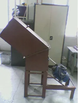
1.1 The grass cutting machine 2
2.1 Flow chart of Lucas Hull method 9
2.2 Show DFA analysis 20
2.3 Show view of Longbow Apache Helicopter 23
2.4 Explode view of existing design of overhead luggage rack 24
2.5 Explode view of new design of overhead luggage rack 25
2.6 BagEasy III 26
3.1 Flow chart of Planning of the Study 28
3.2 The process flow in developing TeamSET database 29
3.3 The product maintaining projects, products and design scenarios 30
3.4 Product Breakdown Structure 31
3.5 Assembly Window 32
3.6 DFA analysis for assembly parts 33
3.7 A flow chart of existing product main part 34
3.8 A flow chart of base part 35
3.9 A flow chart of upper tunnel part 36
3.10 A flow chart of lower tunnel part 36
3.11 View of the existing product 37
3.12 TeamSET analysis for existing product 38
4.1 View of first redesign 40
4.2 View of second redesign 41
4.3 A flow chart of first redesign main part 44
4.4 A flow chart of upper tunnel part after redesign 45
4.6 A flow chart of base part 46
4.7 TeamSET analysis for improvement design 47
4.8 A flow chart of final design main part 49
4.9 A flow chart of base structure part 49
4.10 A flow chart of cylinder blade part 50
4.11 A flow chart of V-belt part 51
4.12 TeamSET analysis for second redesign 52
4.13 Drawing of shaft blade and shaft connector 53
4.14 View of cylinder blade 54
4.15 View of base structure 55
4.16 Cross section view of tunnel 56
4.17 Isometric view of tunnel 56
5.1 Part for accessories 59
5.2 View of the second redesign after installation accessories 60
6.1 Shows the comparison between existing product and second redesign
LIST OF TABLE
2.1 Lucas DFA method - Manual Handling Analysis 11
2.2 Lucas DFA method - Manual Fitting Analysis 12
2.3 Pilot's Instrument Panel Estimate Summary 23
4.1 Quantity List of a first redesign 43
4.2 Quantity List of a second redesign 48
5.1 Comparison of existing design with fisrt redesign 58
LIST OF SIGN & SYMBOL
DFMA - Design for Manufacturing and Assembly DFA - Design for Assembly
DFM - Design of Manufacturing
PDS - Product Design Specification
QFD - Quality Function Deployment
MA - Manufacturing Analysis
FMEA - Failure Modes and Effects Analysis
DTC - Design to Target Cost
ASF - Assembly Flowchart
IPD - Integrated Product Development
PEP - Engineering and Planning
IEFAB - Improved Extended Avionics Bay
CAD - Computer Aided Design
CHAPTER 1
INTRODUCTION
1.1 General Introduction
Product lifecycle is being reduced drastically due to rapid changes in technology and
customers requirements. The global marketplace is changing so rapidly that industrialist
needs to adopt new strategies to respond customer’s requirement and in order to satisfy
the market needs more efficiently and quickly. Many companies especially in Japan,
USA and Europe have already started to implement techniques and tools that would
enable them to respond more quickly to consumer’s demand in delivering high quality
product at reasonable costs. The delay in time-to-market can be interpreted as a loss in
profit (Alan F & Jan Chal, 1994).
Currently, the implementation of Design for Manufacturing and Assembly (DFMA)
methodology are applied either manually or computer-aided. Most of the applied
interested in implementing DFMA are hindered by lack of clear guidelines or procedures
and no integration of isolated design and manufacturing teams. The advantages of the
integration are to decrease the number of part design and indirectly to reduce cost and time. At the same time, it fulfills customer’s requirement. In this project, DFMA has been applied in design and development the grass cutting machine. The design also must be
concerned to the requirement of the DFMA methodology in order to achieve high rank of
1.2 Problem statement
In developing this project, there are several problems that need to be concerned and the
most suitable method that can be used to solve the problems is by applying the Design for
Manufacturing and Assembly (DFMA) methodology. In identifying of grass cutting
machine problems, the most important aspects that need to be concerned is the design of
the grass cutting machine. Some of the part grass cutting machine are being designed
quite complicated with accessories and need to be eliminated, in the same time reduced
the manufacturing cost and assembly time. Besides that, there are several parts had been
recognized that difficult to handle. So, with the application of Design for Manufacturing
and Assembly (DFMA) methodology is highly expected in solving these problems to suit
1.3 Objective
The main objective of this project is using DFMA methodology to design the new grass
cutting machine and compare with the existing product. Beside that, other specific
objectives include:
a) to develop the grass cutting machine;
b) to design and analysis of original design;
c) to purpose grass cutting machine using DFMA method and TeamSET
software;
d) to determine the optimum manufacturing and assembly method for low
cost production with short production time.
1.4 Scope of study
a) Case study
A grass cutting machine has been selected as a case study for this project and had the
potential to be redesign by applying the Design for Manufacturing and Assembly
(DFMA) methodology. The tool selected for drawing the grass cutting machine is
SolidWork. User can easily generate drawing from a model. Photorealistic rendering
and animation that allow communicating how future products will look and perform
early in the development cycle.
b) Design for Assembly (DFA)
DFA is a systematic methodology that reduces manufacturing costs, total number of
parts in a product, and etcetera. For this project, the software called TeamSET is used
CHAPTER 2
LITERATURE REVIEW
2.1 Introduction
To develop this project, the case study is to apply the Design for Manufacturing and
Assembly (DFMA). There are certain important DFMA tools that have been applied such
as Design for Assembly (DFA) and Design for Manufacture (DFM). These two important
DFMA tools are very useful especially to the industry. This chapter described about the
definition of Design for Manufacturing and Assembly (DFMA), Boothroyd Dewhurst
DFA method, the Lucas DFA method, the application of DFMA in industry and
2.2 Design for Manufacturing and Assembly (DFMA)
Design for Manufacturing and Assembly (DFMA) is a design philosophy used by
designers when a reduction in part counts, a reduction in assembly time, or a
simplification of subassemblies is desired. It can be used in any environment regardless
of how complex the part is or how technologically advanced this environment may be.
DFMA encourages concurrent engineering during product design so that the product
qualities reside with both designers and the other members of the developing team
(D-ESPAT, 2007).
According to Geoffrey Boothroyd, Professor of Industrial and Manufacturing at the
University of Rhode Island, the practices now known as Design for Assembly (DFA),
and Design for Manufacture (DFM) had their start in the late 1970's at the University of
Massachusetts. Of all the issues to consider, industry was most interested in Design for
Assembly. When developing a product, the maximum potential cannot be achieved
without considering all phases of the design and manufacturing cycle. DFMA meets this
demand by addressing key assembly factors before the product goes on to the prototype
stage. These key factors are the product appearance, type, the number of parts required in
the product, and the required assembly motions and processes (D-ESPAT, 2007).
The Term “DFMA” comes with the combination of DFA (Design for Assembly) and DFM (Design of Manufacturing). The basic concept of it is that the design engineers
apply the DFMA paradigm or software to analyze the manufacturing and assembly
problems at the early design stage. By this means, all of considerations about the factors
that affect the final outputs occur as early as possible in the design cycle. The extra time
spent in the early design stage is much less the time that will be spent in the repeatedly
redesign. And meanwhile, the cost will be reduced. DFM is that by considering the
limitations related to the manufacturing at the early stage of the design; the design
engineer can make selection among the deferent materials, different technologies,
estimate the manufacturing time the product cost quantitatively and rapidly among the
then the design team will make revises as soon as possible at the early stage of the design
period according this feedback information and determine the most satisfied design and
technology plan.
The three goals in DFM are:
1. Increase the quality of new produces during the development period, including
design, technology, manufacturing, service and so on.
2. Decrease the cost, including the cost of design, technology, manufacturing, delivery,
technical support, and discarding.
3. Shorten the developing cycle time, including the time of design, manufacturing
preparing, and repeatedly calculation.
DFA is considering and resolving the possible problems in the assembly process at the
early stage of the design which can make sure the part will be assembled with high speed,
low cost and productivity. DFA is a kind of design paradigm with which, the engineer
use all kinds of methods such as analyze, estimating, planning and simulating to consider
all the factors that will affect the assembly process during the whole design process;
revise the assembly constructions to satisfied the characteristics and functions of the final
products; and meanwhile, lower the cost as most as possible.
DFA is a kind of design method that can be used in two ways. The ways is a tool for
assembly analysis and a guide for assembly design. The former usage is that at the time
after the beginning of the product design, the engineer makes estimation of assembly
possibility by analyzing all the factors that can affect the assembly process, and give
suggestions. The second one is that collecting the knowledge and experience from the
assembly experts and recording them as design guides. By the help of these guides, the
engineer can choose the design plan and determine the product construction such as
2.3 Boothroyd Dewhurst DFA method
In the history of DFMA, Ford and Chrysler use the DFM philosophy in their design and
manufacturing process of the weapons, tanks and other military products. Dr. Geoffrey
Boothroyd and Dr. Peter Dewhurst who founded the Boothroyd Dewhurst, Inc (BDI) in
1982 are the first persons doing the research job in this new technology at the beginning in the early 1970’s. Actually, the “DFMA” is a trademark of their company. They created and developed the DFMA concept which is used in developing the products of their
company --- DFMA software system. Currently these programs are used to help the
design in almost all the industrial fields including circuit boards (G. Boothroyd & W.
Knight, 1993), with manual assembly, with robotic assembly, and with machining. They also do a lot of work examining the economic justification of each design revision (G.
Causey, 1999).
They created and developed the DFMA concept which is used in developing the products
of their company such as DFMA software system. Currently these programs are used to
help the design in almost all the industrial fields including circuit boards, with manual
assembly, with robotic assembly, and with machining. They also do a lot of work
examining the economic justification of each design revision.
In generally, Boothroyd Dewhurst DFA method can determine the appropriate assembly
method and reducing the number of individual parts to be assembled. This method also
can ensure that the remaining parts are easy to assemble. The methods of assembly are
classified into three basic categories such as manual assembly, special-purpose transfer
2.4 The Lucas DFA method
Although the Boothroyd-Dewhurst method is widely used, it is based on timing each of
the handling and insertion motions. Although tables of data are available, the most
accurate numbers are compiled through time studies in particular factories.
The basic construction of Lucas DFA is very similar to the DFA of BDI, it is the result of
the cooperation of Lucas Organization and the University of Hull in U.K. Now, the logic of Lucas DFA has been integrated in the engineering analysis software “TeamSet” which is the product of CCI Lucas DFA separates the product design process into three stages:
FcA (Function Analysis), HA (Handing Analysis) and FtA (Fitting Analysis). The
relations of these three stages are shown in Figure 2.1. Before the manufacturing and
assembly process, the PDS (Product Design Specification) occurs which change the
requirements of the customs into engineering specifications. After that, the design
engineers perform the design job according to this information. This is a kind of process
to change the engineering specifications into the real design and meanwhile, all the