MASTER OF SCIENCE
IN ELECTRONIC ENGINEERING
DESIGN OF ANTENNA WITH MATCHING AND RECTIFYING
CIRCUIT FOR RADIO FREQUENCY ENERGY HARVESTING
SYSTEM
NUR AISHAH BINTI ZAINUDDIN
Faculty of Electronic and Computer Engineering
DESIGN OF ANTENNA WITH MATCHING AND RECTIFYING
CIRCUIT FOR RADIO FREQUENCY ENERGY HARVESTING
SYSTEM
Nur Aishah Binti Zainuddin
MSc. in Electronic Engineering
DESIGN OF ANTENNA WITH MATCHING AND RECTIFYING CIRCUIT FOR RADIO FREQUNCY ENERGY HARVESTING SYSTEM
NUR AISHAH BINTI ZAINUDDIN
A thesis submitted
in fulfillment of requirements for the degree of Master of Science in Electronic Engineering
Faculty of Electronic and Computer Engineering
UNIVERSITI TEKNIKAL MALAYSIA MELAKA
DECLARATION
I declare that this thesis entitled “Design of Antenna with Matching and Rectifying Circuit for Radio Frequency Energy Harvesting System” is the result of my own research except as cited in the references. The thesis has not been accepted for any degree and is not concurrently submitted in candidature of any other degree.
APPROVAL
I hereby declare that I have read this thesis and in my opinion this thesis is sufficient in terms of scope and quality for the award of Master of Science in Electronic Engineering.
ABSTRACT
ABSTRAK
Pada masa kini, pembangunan komunikasi tanpa wayar telah menjadi satu kepentingan dan menerima permintaan yang besar di seluruh dunia. Seperti mana teknologi sistem komunikasi tanpa wayar sedang berkembang, tenaga atau kuasa yang diperlukan untuk mengendalikan alat-alat tanpa wayar juga semakin meningkat. Walau bagaimanapun, sumber tenaga semula jadi yang terhad telah merangsang beberapa langkah alternatif untuk menghasilkan tenaga yang boleh diperbaharui, termasuk sistem penuaian tenaga. Tujuan projek ini adalah untuk mereka bentuk satu sistem penuaian tenaga berasaskan frekuensi radio (RF) dari ambien atau persekitaran. Alat penuaian tenaga RF ini terdiri daripada tiga sub-sistem utama. Sub-sistem pertama adalah antena penerima, yang bertanggungjawab untuk menyerap semua tenaga RF yang kemudiannya akan digunakan untuk menguasakan seluruh sistem bersepadu yang telah diintegrasikan. Sub-sistem utama kedua adalah litar padanan, yang digunakan untuk memadankan galangan antara antena dan rektifier untuk meminimumkan kehilangan kuasa, seterusnya meningkatkan kecekapan keseluruhan sistem ini. Sub-sistem ketiga adalah litar rektifier, yang cekap menukarkan kuasa RF kepada kuasa arus terus sebagai output. Setiap sub-sistem secara keseluruhannya adalah penting untuk operasi sistem penuai. Sebuah penuai tenaga RF pada frekuensi 2.45GHz adalah dicadangkan. Kerja-kerja yang dibentangkan mengandungi penakrifkan sifat bagi semua sub-sistem dan diteruskan dengan proses reka bentuk yang optimum. Prototaip sistem ini kemudian difabrikasikan untuk ukuran prestasi dan ujian makmal. Dari pengukuran prestasi yang telah dijalankan, sistem tenaga RF ini berjaya menghasilkan voltan arus terus rendah yang boleh digunakan untuk mengendalikan aplikasi dan peranti voltan rendah. Reka bentuk akhir antena beroperasi pada 2.45GHz dengan 14.16dB gandaan dan corak radiasi sehala yang besar. Sementara itu, kadar kecekapan yang diukur bagi rectifier seperingkat dan rectifier berganda
masing-masing adalah sebanyak 13.99% dan 42.46%. Keputusan simulasi dan ukuran
ACKNOWLEDGEMENTS
TABLE OF CONTENTS
1.5 Original Contribution Presented by this Thesis 14
1.6 Thesis Organization 16
2. LITERATURE REVIEW 18
2.0 Introduction 18
2.1 Wireless Communication System 19
2.2 Energy Harvesting System 20
2.3 Radio Frequency (RF) Energy Harvesting System 21 2.3.1 Antenna, Rectifier & Matching Circuit 23
2.4 Design of Antenna 24
2.4.1 Overview of Microstrip Patch Antenna 24 2.4.2 Transmission Line Model of Microstrip Antenna 27
2.4.3 Overview of Array Antenna 28
2.4.3.1 Transmission Line Model for Array Antenna 30
2.4.4 Feeding Method 31
2.4.4.1 Coaxial Feeding 32
2.4.4.2 Proximity Feeding 33
2.4.4.3 Microstrip Line Feeding 33
2.4.4.4 Aperture Feeding 35
2.5 Design of Rectifier 36
2.5.1 Overview of Rectifier 36
2.5.2 Factors That Affect Rectifier’s Performance 40
2.5.2.1 Choice of Diodes 40
2.5.2.2 Number of Stages 40
2.5.2.3 Load Impedance 41
2.7 Recent Review of RF Energy Harvesting System 44 2.7.1 Recent Review of Antenna for RF Energy Harvesting 44 2.7.2 Recent Review of Rectifier for RF Energy Harvesting 49
2.8 Summary 52
3. METHODOLOGY 54
3.0 Introduction 54
3.1 Flow Chart 55
3.2 Design of Antenna 57
3.2.1 Design 1: Rectangular Microstrip Patch Antenna 59 3.2.2 Design 2: Microstrip 1×2 Array Antenna 61 3.2.3 Design 3: Aperture Coupled Microstrip Array Antenna 62 3.2.4 Design 4: Microstrip 2×2 Array Antenna 65
3.3 Design of Microstrip Rectifier 69
3.3.1 Design of Single Stage Rectifier 72 3.3.2 Design of Cascaded Stage Rectifier 72 3.3.3 Interdigital Capacitor and Microstrip Stubs 74
3.4 Simulation Process 78
3.4.1 Antenna Simulation Process 78
3.4.2 Rectifier Simulation Process 80
3.5 Design of Matching Circuit 84
3.6 Fabrication Process 87
3.7 Measurement Process 88
3.7.1 Antenna Measurement 88
3.7.2 Rectifier Measurement 91
3.8 Summary 93
4. RESULTS AND DISCUSSIONS 94
4.0 Introduction 94
4.1 Analyses of Antennas 94
4.1.1 Design 1: Rectangular Microstrip Patch Antenna 95 4.1.2 Design 2: Microstrip 1×2 Array Antenna 98 4.1.3 Design 3: Aperture Coupled Microstrip Array Antenna 101 4.1.4 Design 4: Microstrip 2×2 Array Antenna 104 4.5 Comparison with Other RF Energy Harvesting Systems 130
4.6 Summary 134
5. RECOMMENDATION FOR FUTURE WORKS 135
5.0 Conclusion 135
5.1 Suggestions for Future Works 136
REFERENCES 138
LIST OF TABLES
TABLE TITLE PAGE
2.1 Power density of energy harvesting and their applications 21
2.2 Comparison of rectifiers 37
2.3 Advantages and disadvantages of voltage multipliers 38 2.4 Comparison of typical parameters for common diodes 39
3.1 Design material of antenna 58
3.2 Optimized design parameter of rectangular microstrip patch antenna 61 3.3 Optimized design parameter of microstrip 12 array antenna 62 3.4 Optimized design parameter of aperture coupled microstrip antenna 65
array
3.5 Optimized design parameter of microstrip 22 array antenna 69 3.6 Design specifications of rectifier 70
3.7 Design material of rectifier 70
3.8 Interdigital capacitor dimension’s descriptions 75 3.9 Range of usage of the characteristic specification 75 3.10 Parameters setup for FR-4 substrate 78
3.11 Dimension of probe feed layer 79
4.2 Simulation results of microstrip 1×2 array antenna 101 4.3 Simulation results of aperture coupled microstrip array antenna 104 4.4 Simulated antenna parameters of microstrip 2×2 array antenna at 106 different air gap height, d1
4.5 Simulation results of microstrip 2×2 array antenna 108 4.6 Simulated output voltage of single stage and cascaded rectifier 113 4.7 Simulated output voltage of single stage rectifier circuit with no stub, 114 single stub and double stub matching network at various input power 4.8 Simulated output voltage of cascaded rectifier circuit with no stub, 116 single stub and double stub matching network at various input power 4.9 Power received by the microstrip 2×2 array antenna at different 121 distances
4.10 Measurement result for single stage and cascaded rectifier 123 4.11 Comparison of simulated and measured output voltage for single stage 125 and cascaded rectifier
LIST OF FIGURES
FIGURE TITLE PAGE
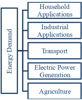
1.1 Recent energy demands for daily usage 1 1.2 Various sources of energy harvesting from ambient 3
1.3 Irrigation sensors application 5
1.4 Sensor network applications in a room 5 1.5 Solar energy conversion system for home use 6 1.6 Biomedical implantable devices sourced by scavenged energy 7
1.7 Various sources of RF signals 8
1.8 RF energy harvesting block diagram 8
2.1 Applications of wireless communication networks 19 2.2 Schematic view of an RF energy harvesting system 22 2.3 Physical structure of microstrip antenna 25 2.4 Common shapes of microstrip patch elements 25 2.5 Structures of typical array antenna 29 2.6 Common type of feeding methods for microstrip antenna 32
2.7 Direct microstrip feed line 34
2.8 Inset micsrostrip feed line 34
2.9 Gap-coupled microstrip feed line 35
2.11 Effect of number of stages on the efficiency of energy harvesting 41 circuit
2.12 Effect of load impedance on the efficiency of energy harvesting 41 circuit
2.13 Possible circuit topologies of matching network 42 2.14 Array antenna structure of 64 spiral elements 46 2.15 Stacked patch antenna array structure 47 2.16 Compact array antenna with reflector 48 2.17 A 3-stage Villard voltage multiplier circuit 49
2.18 Low frequency 5-stage rectifier 50
2.19 Assembled rectifying circuit board 51
3.1 Flowchart of methodology 55
3.2 Structure of rectangular microstrip patch antenna 60 3.3 Structure of microstrip 12 array antenna 61 3.4 Perspective view of aperture coupled microstrip array antenna 63 3.5 Structure view of aperture coupled microstrip array antenna 64 3.6 Structure view of microstrip 22 array antenna 67
3.7 Structure of a basic rectifier 71
3.8 Lumped element circuit of single stage rectifier 72 3.9 Lumped element circuit of cascaded rectifier 73 3.10 Interdigital capacitor basic structure 74 3.11 Introducing the interdigital capacitor and open circuit stub 76
3.12 Characteristic impedance 76
3.13 LineCalc tools in ADS 77
3.15 Summarization of simulation process 80
3.16 Transmission lines insertion 80
3.17 Transmission line tuning process 81 3.18 Example of comparison in tuning process 82 3.19 The replacement of microstrip lines over the transmission lines 82 3.20 Inserting input and output port into the circuit 83
3.21 Microstrip layout 84
3.22 Interdigital capacitor layout in microstrip layout 84 3.23 Matching network in microstrip lines circuit 85 3.24 Rectifier in microstrip layout symbol form with double stub 86
matching network
3.25 Fabricated antenna and rectifying circuits 87 3.26 Equipment for antenna and rectifier fabrication process 88
3.27 Summary of measurement process 89 4.2 Simulated return loss of rectangular microstrip patch antenna 96 4.3 Simulated gain of rectangular microstrip patch antenna 96 4.4 Simulated radiation pattern of rectangular microstrip patch antenna 97 4.5 Simulated VSWR of rectangular microstrip patch antenna 97
4.6 Microstrip 12 array antenna 98
4.8 Simulated gain of microstrip 1×2 array antenna 99 4.9 Simulated radiation pattern of microstrip 1×2 array antenna 100 4.10 Simulated VSWR of microstrip 1×2 array antenna 101 4.11 Aperture coupled microstrip array antenna 101 4.12 Simulated return loss of aperture coupled microstrip array 102
antenna
4.13 Simulated gain of aperture coupled microstrip array antenna 102 4.14 Simulated radiation pattern of aperture coupled microstrip array 103
antenna
4.15 Simulated VSWR of aperture coupled microstrip array antenna 104
4.16 Microstrip 2×2 array antenna 104
4.17 Analyses of air gap height of microstrip 2×2 array antenna 105 4.18 Simulated return loss of microstrip 2×2 array antenna 106 4.19 Simulated gain of microstrip 2×2 array antenna 107 4.20 Simulated radiation pattern of microstrip 2×2 array antenna 107 4.21 Simulated VSWR of microstrip 2×2 array antenna 108 4.22 Lumped element design of single stage Villard voltage multiplier 109 4.23 Optimized simulated DC output voltage of single stage rectifier 110
circuit
4.24 Comparison of simulated output DC voltage for single stage 111 rectifier circuit with different type of diodes 4.25 Comparison of simulated output DC voltage for single stage 112 rectifier circuit with different value of loads
4.26 Comparison of simulated output DC voltage for single stage and 113
4.27 Comparison of output voltage for single stage rectifier circuit with 115 no stub, single stub and double stub matching network 4.28 Comparison of output voltage for cascaded rectifier circuit with no 117 stub, single stub and double stub matching network 4.29 Comparison of simulated efficiency for single stage and cascaded 117
rectifier
4.30 Simulated and measured return loss characteristic of microstrip 120
2×2 array antenna
4.31 Measured radiation pattern of microstrip 2×2 array antenna 120 4.32 Experimental setup for power receive measurement 121 4.33 Measurement process for the rectifier performance 122 4.34 Comparison of measured output DC voltage for single stage and 123
cascaded rectifier
4.35 Comparison of measured efficiency for single stage and cascaded 124
rectifier
4.36 Measurement setup for RF energy harvesting system performance 126 4.37 Measured output DC voltage of single stage rectifier at different 129
distances
LIST OF ABBREVIATIONS
AC - Alternating Current ADS - Advanced Design System
BiCMOS - Bipolar Complimentary Metal-Oxide-Semiconductor CPW - Coplanar Waveguide
CST - Computer Simulation Technology DC - Direct Current
EM - Electromagnetic
GSM - Global System for Mobile ISM - Industrial Scientific & Medical PC - Personal Computer
PCB - Printed Circuit Board RF - Radio Frequency TV - Television UV - Ultra Violet
LIST OF APPENDICES
APPENDIX TITLE PAGE
A FR-4 Material and Characteristics 158
B HSMS-286X Diode Data Sheet 159
C LM94022 Data Sheet 161
D Flow Chart of Research Step 162
LIST OF PUBLICATIONS
The research papers produced and published during the course of this research are as follows:
1. Zahriladha Zakaria, Nur Aishah Zainuddin, Mohd Nor Husain, Mohamad Zoinol Abidin Abd Aziz, Mohamad Ariffin Mutalib, Abdul Rani Othman, “Current Developments of RF Energy Harvesting System for Wireless Sensor Networks”, Advances in Information Sciences and Service Sciences (AISS), Vol. 5, No. 11, pp.
328-338, June 2013.
2. Zahriladha Zakaria, Nur Aishah Zainuddin, Mohd Nor Husain, Bazilah Mohd Derus, Mohamad Zoinol Abidin Abd Aziz, Mohamad Ariffin Mutalib, “Investigation of Wideband Coplanar Antenna for Energy Scavenging System”, Australian Journal of Basic and Applied Sciences, Vol. 8, No. 4, pp. 270-277, 2014.
3. Zahriladha Zakaria, Nur Aishah Zainuddin, Mohd Nor Husain, Mohamad Zoinol Abidin Abd Aziz, Mohamad Ariffin Mutalib, “Investigation of Compact Tree-Shaped Coplanar Waveguide (CPW) Antenna for RF Energy Harvesting”, Journal of Applied Mechanics and Materials, Vol. 699, pp. 903-908, November 2014.
DC Conversion for Ambient RF Energy Harvesting”, Journal of Applied Mechanics and Materials, Vol. 699, pp. 909-914, November 2014.
5. Zahriladha Zakaria, Nur Aishah Zainuddin, Mohd Nor Husain, Mohd Nabil Imran Kamaruzaman, Mohamad Zoinol Abidin Abd Aziz, Nor Zaidi Haron, Mohd Sa’ari Mohamad Isa, Mohamad Ariffin Mutalib, “Design of Antenna with Rectifying Circuit for Low Power Wireless Sensor Network Application”, Advanced Science Letters, Vol. 20, No. 10-12, pp. 1788-1792, October 2014.
6. Zahriladha Zakaria, Nur Aishah Zainuddin, Mohamad Zoinol Abidin Abd Aziz, Mohd Nor Husain, Mohamad Ariffin Mutalib, “Dual-Band Monopole Antenna for Energy Harvesting System” IEEE Symposium on Wireless Technology and Applications, pp.225-229, Kuching, Sarawak, 22-25 September 2013.
7. Zahriladha Zakaria, Nur Aishah Zainuddin, Mohamad Zoinol Abidin Abd Aziz, Mohd Nor Husain, Mohamad Ariffin Mutalib, “A Parametric Study on Dual-Band Meander Line Monopole Antenna”, IEEE International Conference on RFID Technologies and Applications, Johor Bahru, Johor, 4-5 September 2013.
AWARDS
2014
Bronze Medal – Analysis of Receiving Antenna Structures with High Efficiency Rectifying Circuit for Radio Frequency (RF) Energy Harvesting System, Malaysia Technology Expo (MTE), Putra World Trade Centre (PWTC), Kuala Lumpur, 20th - 22th
February 2014.
2013
1 CHAPTER 1
INTRODUCTION
1.0 Research Background
Energy is a basic necessity for sustaining human life, which pervades each and every one of our activities. In the very early days, muscle power was rendered from human and animals to drive simple implements and machines, which could only run for a limited time and had limitations on their continuous availability. Nevertheless, the greatest transition took place when we learnt to generate energy by transforming one state of energy, possibly latent, to another. After that, vast possibilities opened up where energy could be obtained, stored, and transferred across large distances. Figure 1.1 shows the string of energy demands in worldwide at present.
Figure 1.1: Recent Energy Demands for Daily Usage
Besides, as an essential keystone in furthering the reach of technology, it is becoming difficult to meet the insatiable need of energy today. According to International Energy Agency (IEA) (2014), the increasing energy demands have put a strain on the current energy sources. Thus, there is an incessant effort to identify new sources of energy that may partially satisfy the energy demands and conserve our finite natural resources for the years to come.
Renewable energy sources provide an alternative to conventional natural sources, of which there are limited supplies. Renewable energy can be broadly defined as a kind of energy that is generated from natural sources, which is not typically depleted, such as sunlight, wind, rain, heat, and RF signal, among others. Renewable energy is derived from natural processes that are replenished constantly. Some additional features of renewable energy sources that make them an attractive alternative to the classical natural sources are:
Renewable energy sources are often accessible without geographical and national barriers, although certain regions may be more conducive to their large-scale use.
Renewable energy sources are generally not harmful, which adversely affect the environment. Hence, they are green technologies and are safe to use. These sources are unlimited in the near term, which get used up faster every
day. They are generally free to harness, although specialized equipment may be needed for high conversion efficiency.