DESIGN OF ANTENNA AT 1.8GHz WITH RECTIFYING CIRCUIT FOR RF ENERGY HARVESTING
MOHD NABIL IMRAN BIN KAMARUZAMAN
This Report Is Submitted In Partial Fulfillment Of Requirement For The Bachelor Degree of Electronic Engineering (Telecommunication)
Fakulti Kejuruteraan Electronik dan Kejuruteraan Komputer Universiti Teknikal Malaysia Melaka
v
DEDICATION
To To Allah
I devoted my life and death to You, Allah. May my life is within Your guidance.
To My Mother
Tuan Kamariah Binti Ibrahim
Thank you for your sacrifice and love. No such compensate except from Allah.
To My Supervisor and Lecturer’s
Thank you for all the knowledge and support. Your support, patience, and
encouragement give me strength throughout the whole course. May Allah bless us.
To all friends
vi
ACKNOWLEDGEMENT
In the Name of Allah, Most Gracious, Most Merciful
Assalamualaikum…..
First and foremost, I would like to thank ALLAH for giving me strength to
complete the final year project from September 2012 until June 2013. Who gave me
an opportunity, courage and patience to carry out this work. I feel privileged to glory
His name in the sincerest way through this small accomplishment. I seek His mercy,
favor and forgiveness.
I would like to express my deepest gratitude to my Supervisor, Dr.Zahriladha
bin Zakaria for his constant patience, support and constructive guidance for this
project. Special thanks also to Dean and Deputy Dean of FKEKK, all the Lecturers
who taught me throughout my course. I would also like to thank the technician at
LAB for his cooperation and support.
Last but not least, Thanks to my beloved mother Tuan KamariahBt Ibrahim
and my family for supporting me throughout my final year project. Without your
support, I will never get to complete my final year project.
vii
ABSTRACT
This thesis presents the design of antenna at frequency 1.8GHz with a
rectifying circuit for RF energy harvesting system. This system is a combination of a
receiving antenna and integrated to a rectifying circuit that efficiently converts RF
energy to DC signals for power harvested. Microstrip patch antenna design has been
chosen as receiving antenna design due to its low profile, low cost and ease of
fabrication. Two types of antenna i.e, rectangular patch and circular patch antenna
design have been proposed in this project as a receiving part in the energy harvesting
system. The design process of antenna has been done by taking consideration of all
antenna parameters including return loss, gain, bandwidth and directivity. The
RF-DC energy conversion module is a voltage doubler or rectifier circuit used to convert
the harvested energy received by the antenna from ambient RF sources to DC
voltage. The RF signals received by the antenna will be transformed into DC signals
by a diode based rectifying circuit or voltage multiplier. For this RF energy
harvesting system design, the Villard voltage multiplier circuit is presented for
energy conversion where the rectifier circuit. Lastly, the integration between the
antenna and rectifying circuit is successful implemented to obtain a reliable DC
viii
ABSTRAK
Tesis ini menerangkan tentang rekabentuk antenna pada frekuensi 1.8GHz
bersama dengan litar penerus untuk tujuan sistem penuai tenaga RF. Sistem ini
adalah kombinasi antara antenna penerima dan disambungkan kepada litar penerus
yang berfungsi menukarkan isyarat tenaga RF yang diterima kepada bentuk arus
terus (DC) sebagai kuasa yang dituai. Rekabentuk mikrostrip tampalan antena telah
dipilih sebagai antena penerima kerana mempunyai ciri-ciri seperti profil yang
rendah, kos rendah dan proses fabrikasi yang mudah. Dua jenis rekabentuk antena
i.e. iaitu tampalan segi empat tepat dan tampalan tampalan bulat telah dicadangkan
didalam projek ini sebagai sebahagian dari bahagian penerima didalam sistem tuaian
tenaga. Proses merekabentuk antenna telah dilakukan dengan mengambil kira semua
antenna paramater termasuk „return loss‟, „gain‟, „lebar jalur dan „directivity‟. Sistem
penukaran tenaga RF-DC adalah pengganda voltan atau litar penerus yang
digunakan untuk menukarkan tenaga yang diterima oleh antena dari sumber RF pada
persekitaran ke bentuk voltan DC. Untuk tujuan rekabentuk sistem tuaian tenaga RF
ini, litar yang dicadangkan adalah litar pengganda voltan Villard untuk tujuan
penukaran tenaga. Akhir sekali, gabungan antenna dan litar penerus telah berjaya
dilaksanakan untuk mendapatkan voltan keluaram DC sebagai bukti untuk sistem
ix
CONTENT
CHAPTER TITLE PAGE
TITLE PROJECT i
DECRALATION ii
DECRALATION iii
SUPERVISROR DECRALATION iv
DEDICATION v
ACKNOWLEDGEMENT vi
ABSTRACT vii
ABSTRAK viii
CONTENT ix
LIST OF TABLE xii
LIST OF FIGURE xiii
LIST OF ABBREVIATIONS xvi
I INTRODUCTION
1.1 Introduction 1
1.2 Project Objective 2
1.3 Problem Statement 2
1.4 Scope of Work 3
1.5 Methodology 4
x
II LITERATURE REVIEW
2.1 Introduction 7
2.2 RF Energy Harvesting System 7
2.3 Operating Frequency 11
2.4 Introduction of Antenna 12
2.5 Microstrip Patch Antenna 12
2.5.1 Bandwidth Improvement 14
2.5.2 Circular Patch Antenna 15
2.6 Feeding Method 16
2.7 RF-DC Conversion 17
III METHODOLOGY
3.1 Introduction 19
3.2 Antenna Design Specification 21
3.3 Antenna Design 22
3.3.1 Rectangular Microstrip Patch Antenna 22
3.3.2 Rectangular Patch Antenna with Notch 23
3.3.3 Circular Patch Antenna Design 24
3.4 Rectifier Circuit Design 27
3.4.1 Transmission Line and Microstrip Line Conversion 31
3.4.2 Generate Microstrip Layout 33
3.5 Antenna Measurement Process 35
3.5.1 Parameter Measurement 35
3.5.2 Radiation Pattern Measurement 35
IV RESULT AND DISCUSSION
4.1 Introduction 37
4.2 Simulation Result 37
4.3 Circular
xi
4.3.1 Basic Circular Patch Antenna Design 38
4.1.2 Circular Patch Antenna Design with Notch 40
4.4 Rectangular Patch Antenna Design and
Practical Implementation 45
4.4.1 Rectangular Patch Antenna Design 46
4.4.2 Rectangular Patch Antenna with Notch Design 48
4.5 Rectifier Circuit Design 52
4.5.1 Single Stage Rectifier Circuit 52
4.5.2 Effect of Load in Rectifier Circuit 57
4.6 Antenna Connecting With Rectifier Circuit Measurement 59
4.6.1 Circular Patch-Circular Patch Antenna Measurement 59
4.6.2 Horn Antenna-Circular Patch Antenna Measurement 61
4.6.3 Rectangular -Rectangular Patch Antenna Measurement 63
4.6.4 Horn Antenna-Rectangular Patch Antenna Measurement 64
V CONCLUSION
5.1 Introduction 68
5.2 Conclusion 68
5.3 Future Work 69
xii
LIST OF TABLES
NO TITLE PAGE
2.1 Summary of Literature Study 9
2.2 Frequency Allocation of Cellular Mobile (MCMC) 11
2.3 Operating Frequency for Celcom 11
3.1 Design Specification of Patch Antenna 21
3.2 Design Material of Microstrip Patch Antenna 21
3.3 Probe Feed Dimension 26
3.4 Interdigital Capacitor Basic Structure 29
4.1 Circular Patch Design Parameter 39
4.2 Circular Patch with Notched Design Parameter 41
4.3 Single Mode and Dual Mode Comparison 43
4. 4 Measurement and Simulation Result Comparison 44
4.5 Parameter of the Material 46
4.6 Antenna Design Parameter Value 46
4.7 Rectangular Patch Antenna Design Parameter 49
4.8 Measurement and Simulation Result Comparison 52
4.9 Rectifier Measurement Result 55
4.10 Effect of Load 58
4.11 Measurement result 60
4.12 Effect of antenna distance 62
4.13 Measurement result 63
4.14 Measurement Result By using Horn Antenna as Transmitter 65
xiii
LIST OF FIGURE
NO TITLE PAGE
1.1 RF energy harvesting block diagram 1
1.2 Project flow chart 5
2.1 RF Energy Harvesting System Conceptual Views 8
2.2 Microstrip patch elements shape example 13
2.3 Rectangular Patch Antenna Physical Structure 14
2.4 Notch introducing 15
2.5 Circular Patch Antenna Geometry 15
2.6 Feeding method (a) Inset Feed (b)Probe Feed (c) Proximity
Coupling (d) Aperture Coupling 16
2.7 Single stage voltage multiplier circuits 17
3.1 Project Methodology 20
3.2 Antenna Design Parameter 23
3.3 Antenna Design Structure 23
3.4 Rectangular Patch Antenna with Notch 24
3.5 Circular Patch Design Parameter 25
3.6 Circular Patch Antenna with Notch 25
3.7 Probe Feed Connector Structure 26
3.8 Antenna Design Structure (a) front view (b) back view 26
3.9 Single Stage Villard Voltage Multiplier 27
3.10 Lumped Element Circuit 27
3.11 Interdigital capacitor 28
3.12 Introducing of Interdigital Capacitor and Open Circuit Stub 29
3.13 Characteristic Impedance 29
3.14 LineCalc Tools In ADS 31
xiv
3.16 Transmisssion line Tuning Process 32
3.17 Comparison Result after Tuning Process 32
3.18 Microstrip line Stage 33
3.19 Adding Port Into The Circuit 33
3.20 Microstrip Layout 34
3.21 Microstrip Layout in Symbol Form 34
3.32 S-Parameter Measurement Setup 35
3.33 Radiation pattern Measurement Setup 36
4.1 Basic Circular Patch antenna (a) front view (b) perspective view 39
4.2 Return Loss Result 39
4.3 (a) Antenna gain (b) Antenna directivity 40
4.4 Antenna Structure 41
4.5 Return loss 42
4.6 (a) Antenna gain (b) Antenna directivity 42
4.7 Return loss dual mode antenna 1.84GHz 43
4.8 In lab test measurement result for 1.84GHz antenna 43
4.9 Fabricated Antenna 44
4.10 Measurement and Simulation Result Comparison (S-parameter) 44
4.11 Rectangular Patch Antenna at 1.84GHz (a) front
(b) perspective view 47
4.12 Antenna Return loss result 47
4.13 Antenna Result (a) gain (b) directivity 48
4.14 S-Parameter Result 49
4.15 Antenna Gain and Directivity 50
4.16 Fabricated Antenna 50
4.17 Measurement S-Parameter Result 51
4.18 Measurement and Simulation Comparison for S-parameter Result 51
4.19 Single Stage Villard Voltage Multiplier (Lumped Element) Design 53
4.20 Replacing Capacitor into Interdigital Capacitor & Stub 53
4.21 Simulation Result 53
4.22 (a) Microstrip Layout in ADS, (b) Fabricate Circuit 54
4.23 Measurement Process 54
4.24 Output Graph for Measurement Result 56
xv
4.26 Effect of Load To The Rectifier Performance 58
4.27 Measurement Process 59
4.28 Measurement Result 60
4.29 Horn Antenna as a Transmitter 61
4.30 Antenna Distance vs Output Voltage Graph 62
4.31 Rectangular patch antenna Input Signal vs Output Voltage graph 64
4.32 Horn –Rectangular Patch Antenna Measurement Process 64
4.33 Distance vs Output Voltage Result for Horn-Rectangular Patch
antenna 66
xvi
LIST OF ABBREVIATIONS
AC Alternative Current
ADS Advanced Design System
CST Computer Simulation Technology
DC Direct Current
GSM Global System for Mobile Communication
1
CHAPTER I
INTRODUCTIONS
1.1 Introduction
This chapter will introduce the overall objectives of the project. Energy
harvesting is the process of capturing energy that are available from different source
such as RF source, solar energy or piezoelectric [1] .Radio frequency (RF) energy
harvesting is the process of capturing ambient RF signal where this signal is in the
form of electromagnetic energy and converting this signal into suitable DC power.
This system is a combination of a receiving antenna integrated to a rectifying circuit
that efficiently converts RF energy to DC signals. The basic RF harvesting system
consist of a microwave antenna, impedance matching network, rectifier circuit, the
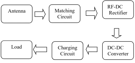
next stage of low pass filter for DC path and a resistive load. Figure 1.1 shows the
[image:17.595.188.445.597.717.2]basic block diagram of RF energy harvesting system.
Figure 1.1: RF energy harvesting block diagram
Antenna Matching
Circuit
RF-DC Rectifier
DC-DC Converter Charging
2
The RF energy system requires the use of antenna as an efficient RF signal
power receiving circuit [2]. In transmitting system the RF signal is generated,
amplified, modulated and applied to the antenna. Meanwhile, in receiving systems
the antenna collects electromagnetic waves that are „cutting‟ through the antenna and
induce alternating currents that are used by the receiver. An antenna ability to
transfer energy from the atmosphere to its receiver with the same efficiency as it
transfers energy from the transmitter into the atmosphere. The RF signals received by
the antenna will be transformed into DC signals by a diode based rectifying circuit or
voltage multiplier. This project will represent the design of antenna with rectifying
circuit based on a concept of RF energy harvesting system. The CST Studio Suite
software will be used for design process of antenna and ADS-2008 software will be
used to design rectifier circuit.
1.2 Project Objectives
The objective of this project is to design an antenna with a rectifying circuit
for RF energy harvesting system at operating frequency of 1.8GHz. Two types of
antenna design have been proposed in this project as a receiving part in the energy
harvesting system. The design of the antenna with rectifying circuit is expected to
achieve higher efficiencies of RF-DC conversion for a maximum power transfer.
1.3 Problem statement
In recent years, there is a rapid increase in using of wireless devices in many
applications such as mobile phones and sensor networks. These devices are powered
by a portable and limited energy device such as a battery. This means that the
increasing of application usage will cause the used of batteries also increased and
these battery needs to be replaced so often. These batteries are containing of heavy
metals, where if we improperly disposed it can leak it contain into the surrounding
environment thus increased pollution. Thus, the use of green technology like this RF
3
wireless broadcasting and communication system that generated the availability of
free energy.
The main problem in RF energy harvesting system is the amount of captured
energy from ambient RF sources is very low. This low level power maybe caused by
the level of RF energy and the mismatching of the antenna to the rectifier. In order
to capture maximum power, the receiving antenna should be designed properly by
taking consideration of many factors to achieve impedance matching between the
antenna and the rectifier at the operating frequency and also to obtain maximum
power transfer and reducing transmission loss from PCB traces. Thus, to convert
more of the antenna surface incident RF power to DC power, high efficiency of RF
to DC conversion is required by the rectifying circuit.
1.4 Scope of work
The main objective of this project is to design a narrowband antenna with a
rectifying circuit for the energy harvesting system. The first step in designing process
is to find and gather the information regarding to the project such as from journal and
paperwork on the internet. This project will focus on design and analysis, testing and
measurement of microstrip patch antenna capture electromagnetic energy from RF
signals that have been radiated by the communication system at GSM 1800
frequency range. Computer Simulation Technology or CST Studio Suite will be used
for design process of antenna. There are two types of antenna will be designed that is
a circular patch antenna and rectangular patch antenna. After complete the design
process, the next procedure is to fabricate the circuit and doing the testing and
measurement procedure. Then, the result will be compared within the measurement
result and the actual result. Other antenna parameters such as return loss level, gain,
and radiation pattern also will be look of antenna design. The rectifier circuit will be
designed by using the Advance Design System (ADS 2011) software. For this RF
energy harvesting system design, the proposed used of Villard voltage multipliers are
presented. The combination between antennas with the rectifying circuit will be
tested by using lab equipment to measure the performance of RF-DC conversion.
The performance of the circular patch antenna will be compared to the rectangular
4
1.5 Methodology
This project will begin by doing the literature review process to study and
learn about the antenna fundamentals, the rectifier circuit and basic RF energy
harvesting system. After all the parameter involves in this antenna design is
calculated, the physical layout of the design antenna will be constructed. Then the
simulation will be carried out by using the CST software. The design of the antenna
will be optimized by considering all antenna basic characteristics such as a resonance
frequency, return loss, bandwidth, gain, and directivity. After completing the design
process for both antenna types, the antenna will be fabricated. The fabricated antenna
then will be measured to observe the result of return loss, bandwidth, gain and
directivity of the antenna. For rectifier part, the rectifier circuit will be designed
using the ADS software after the suitable circuit topology has been determined.
When all the specification meets the requirement, the fabrication process of the
antenna and rectifier circuit will be carried out. Next the testing and measurement of
the fabricated antenna and rectifier will be carried out hence again will compare it
with all the calculated and simulated results. All experimental results will be
5
NO
YES
NO
[image:21.595.142.466.74.717.2]YES
Figure 1.2: Project flow charts Start
Fabrication / Manufacturing [Measurement / Testing] Design and simulation of
the integrated between antenna and rectifying
circuit
Design and simulation antenna
Define specification of antenna and rectifying circuit for energy harvesting
system
End OK
6
1.6 Chapter Review
Chapter 1 describes the general overview of this project. This chapter
presents the objectives, problem statement and review of all chapters of this thesis.
Chapter 2 describes the introductions to the antenna and microstrip antenna is
presented. This chapter will explain the basic concept of the antenna. Then the
introduction of the microstrip patched antenna concept and design will be introduced.
This chapter also gives the information about the parameter and synthesis technique
involved in this antenna design project. Next, this chapter will explain the basic
concept of rectifier circuit as a function of RF-DC conversion and synthesis
technique involved in this rectifier design process.
Chapter 3 presents the methodology used or the design process in this project.
The methodology involves the procedure of getting important data regarding to the
antenna design and rectifier circuit design. The method that had been used, the
equation usage and calculation process also included in this part. This section also
explains about the optimization process that involved in this project.
Chapter 4 presents the results achieved from this project. These results
involve the simulation and measurement result of the antenna, the comparison
between the measurement and simulation, the simulation and measurement result of
rectifier circuit, and the output power transfer obtained from the combination
between the antenna and rectifier circuit for RF-DC conversion also included.
Chapter 5 will present the conclusion of this project. After all the theoretical,
simulated and experimental result is achieved, the conclusion comes to conclude the
7
CHAPTER II
LITERATURE REVIEW
2.1 Introduction
This chapter will explain the basic concept of the RF energy harvesting
system, antenna and rectifying circuit. Then the introduction of the microstrip
patched antenna concept and design will be introduced. This chapter also gives the
information about the parameter and process technique involved in this antenna
design and rectifying circuit.
2.2 RF Energy Harvesting System
Energy is everywhere in the environment surrounding us and available in many
forms such as thermal energy, solar energy, wind energy and radio frequency (RF)
energy. Energy harvesting is the process of capturing energy from one or more of
this energy, accumulating and storing them for later use [3]. RF energy harvesting is
the idea of capturing transmitted RF energy at ambient and converts it into suitable
DC power either storing it to later user or using it directly to power up a low power
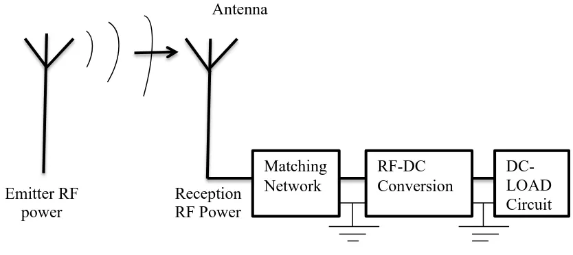
circuit. The principle behind RF energy harvesting system is shown in Figure 2.1
where this system consist of an antenna, matching network, rectifier circuit for
8
Figure 2.1: RF Energy Harvesting System Conceptual Views
The concept of this energy harvesting system needs an efficient antenna
connecting with a circuit that capable to convert received RF signals to DC form.
The antenna is one of the important parts in an RF energy system because it is
responsible for capturing radiated energy from a nearby source. Thus, the choice of
antenna type and its frequency band is very essential to optimize the harvested DC
power. The gain of the antenna must be as high as possible in order to capture high
RF energy. Other antenna parameter including radiation pattern, return loss and
bandwidth could affect the amount of power received by the antenna.
RF signal received by the antenna is in AC form and it cannot be used to power
up the application that used DC to turn them on. Thus, the rectifier circuit that
consists of simple diodes and capacitor is used to convert the AC signal to DC signal.
Although the RF signals carry low energy, the receivable power since then can be
high enough to turn on low power sensor or low power circuits.
Before beginning with the design process, research was carried out by
performing a literature review on several journals related to research topics of RF
energy harvesting system. Literature studies have been conducted on journals to
collect relevant information and facts that can be used in the design process of this
project. Table 2.1 shows a sample summary of the literature reviews that have been