Design of Wideband Antenna for RF Energy
Harvesting System
N. A. Zainuddin, Z. Zakaria, M. N. Husain, B. Mohd Derus, M. Z. A. Abidin Aziz, M. A. Mutalib, M. A. Othman
Centre of Telecommunication Research and Innovation (CeTRI), Faculty of Electronic and Computer Engineering,Universiti Teknikal Malaysia Melaka (UTeM), Hang Tuah Jaya, 76100 Durian Tunggal, Melaka, Malaysia
[email protected], [email protected]
Abstract— This paper studies a wideband antenna of ice-cream cone structure and it is integrated with a rectifying circuit which has the potential to be used for RF energy harvesting system. The antenna is designed by using CST Studio Suite 2011 and fabricated on a double sided FR-4 printed circuit board using an etching technique. A single stage rectifying circuit is designed, simulated, fabricated and measured in this work. The design and simulation process was done by using Agilent Advanced Design System (ADS) 2011. Simulation and measurement were carried out for various input power levels at the specified frequency band. An experimental test has been conducted by varying the load, R of the rectifying circuit. For an equivalent incident signal of 20 dB, the system managed to produce 0.09V with load of 20k''. This voltage can be used to power low power sensors in sensor networks ultimately in place of batteries.
Keywords—RF energy harvesting, wideband antenna, rectifying circuit, energy conversion, Schottky diode.
I. INTRODUCTION
The RF energy harvesting system is known as remotely powered device that converts RF to DC power without requiring any internal source while extracting its power from propagating radio waves [1]. However, the electrical power generated by energy harvesting techniques is small and less than few milli-watts depending on the techniques. However the power derived is enough for small electrical or low power consumption devices. Thus, energy harvesting technology promotes a promising future in low power consumer electronics and wireless sensor networks. Fig. 1 shows the basic block diagram of an energy harvesting system.
Fig. 1: Block diagram of energy harvesting system
RF energy harvesting is a green technology that suitable for a wide range of wireless sensing applications such as wireless sensor networks, wireless power as well as used in RFID tags and implantable electronics devices [2][3][4][5]. The RF energy harvesting system is made up of a microwave antenna, a matching circuit, rectifying circuit and a resistive load.
The RF signals received by the antenna will be transformed into DC signals by a diode based rectifying circuit. In order to obtain an optimum power transfer, a matching circuit and rectifier will be used. The matching circuit is used in this stage to achieve impedance matching between the antenna and rectifier. However, for this wideband antenna for RF energy harvesting system, there are several range frequencies need to be covered particularly at 2.3GHz (WiMax), 2.4 GHz (WLAN), 2.6 GHz (LTE/4G) and also 5.2 GHz (WLAN). The applications particularly use as low-power sensor networks in remote areas [6].
II. ANTENNA AND RECTIFIER DESIGN
A. Antenna
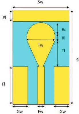
A coplanar ice cream cone antenna is chosen due to its wideband characteristic which could cover several ranges of frequencies. It is basically a combination of triangle, rectangle and circular shape patches attached to a microstrip feeding line.
The proposed wideband monopole antenna is fed by a coplanar waveguide (CPW) line where the central conductor is separated from a pair of ground planes. The CPW offers several advantages including the ability to work in lower frequencies and ease of fabrication.
Fig. 2: The design parameters for the coplanar ice cream cone antenna
Table 1 shows the details of the dimension for coplanar ice cream cone antenna.
TABLE I. THEDIMENSION OF COPLANAR ICECREAMCONEANTENNA
Symbol Design parameters Dimension
(mm)
Sw Substrates width 30
Sl Substrates length 50
Fw Feedline width 4
Fl Feedline length 20
Gw Ground width 8
Pl Patch length 6
Rc Radius circle 7.521
Rl Rectangle length 2
Tw Triangle width 15
Tl Triangle length 13.85
B. Rectifying Circuit
Rectifier is an electrical circuit that converts RF power from a lower voltage to a higher DC voltage using a network of capacitors and diodes [7]. A single diode rectifier is chosen to be integrated with the antenna where the HSMS-286B diode is used. The HSMS-286X family is classified as biased detector diodes that been designed and optimized for use from 915 MHz to 5.8 GHz frequency range. They are ideal for RFID and RF tag applications as well as large signal detection, modulation, RF to DC conversion or voltage doubling [8]. Therefore, it is suitable for the energy harvesting system that been conducted at frequency range of 2 GHz to 4 GHz.
To design the rectifying circuit, the transmission line of the circuit needs to be calculated. The values are then used as the initial parameters in the ADS software before tuning them for optimized performance. For this rectifying circuit, the single stage rectifier design consists of one diode and one capacitor as shown in Fig. 3.
Fig. 3: The single diode rectifying circuit in schematic view
This circuit is chosen as it is less complex and minimizes the diode losses. Therefore, the diode which is used in this design is Schottky diode model HSMS-286B. The transmission line of the rectifying circuit is calculated using the formula given [7][9].
Ʌ ൌ Ⱦ ൌ
னୡൌ
ଶୡ (1) ୧୬ൌ ቀɘ െ
னୡଵቁ
(2) ൌ ඥ
୧୬ൈ
(3)where c = the free space speed of light, ͵ ൈ ͳͲ଼m/s
ZL= the impedance of 50 Ω
f= the resonant frequency
The design of rectifier circuit has been optimized and before converted into microstrip layout as shown in Fig. 4.
Fig. 4: The single diode rectifying circuit in momentum view
III. EXPERIMENTAL RESULTS AND ANALYSIS
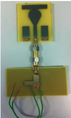
The antenna is then fabricated in-house and the photograph of the prototype can be seen in Fig. 5. An experimental
R P_1Tone
di_hp_HSMS286B_20000301
C
R1 PORT1
D1
C1
measurement also has been made to validate the simulation results.
Fig. 5: Antenna prototype of coplanar ice cream cone antenna
A. Antenna
1) Return loss, bandwidth and gain: S-parameter simulations of the antenna have been carried out using the Computer Simulation Tool 2011. Fig. 6 shows the simulated and measured return losses of the antenna.
Fig. 6: Simulation and measured return loss of coplanar ice cream cone antenna
The measured return loss is in line with the simulation response where both manage to achieve lower than -10 dB. However, measurement result shows better return loss than the simulated one but the resonant frequencies were shifted.
From the simulated data, the coplanar ice cream cone antenna caters a frequency range from 2.17 GHz to 4.2 GHz with a bandwidth of 2.03 GHz. While from the measured data, a frequency range from 3.20 GHz to 5.99 GHz with a bandwidth of 2.79 GHz is successfully achieved. Table 2 shows the comparison of simulation and measurement result for the planar dual-band monopole antenna.
TABLE II. SIMULATION AND MEASUREMENT RESULT OF COPLANAR ICE
CREAM CONEANTENNA
Desired Freq.
Return Loss (dB)
Bandwidth
(GHz) 2.3
GHz
Sim. -10.78 1.98
Meas. -3.14 NA
2.4 GHz
Sim. -11.46 1.98
Meas. -2.95 NA
2.6 GHz
Sim. -12.01 1.98
Meas. -2.73 NA
5.2 GHz
Sim. -14.14 1.98
Meas. -14.32 2.93
The differences between simulation and measurement result are caused by the losses influenced cables and connectors. However, the simulation results prove that the antenna is able to cater the operation of all four frequency bands.
2) Radiation pattern and surface current: The radiation characteristics are also investigated and shown in Fig. 7.
(a) (b)
(c) (d)
Fig. 7:Antenna’s radiation pattern at 3.4 GHz for (a) e-plane simulation (b) h-plane simulation (c) e-plane measurement (d) h-plane measurement
Both simulated and measured radiation pattern indicates that the antenna radiates directionally. The different patterns of simulation and measurement are observable and this might be caused by the environment around the antenna such as metallic influence which affected the measurement process.
Fig. 8: Simulated radiation patterns of coplanar ice cream cone antenna
B. Rectifying circuit
The single diode rectifier is then fabricated in-house and the photograph of the prototype can be seen in Fig. 9. An experimental measurement also has been made to validate the simulation results.
For rectifying circuit, the simulation results obtained from ADS needs to be analyzed in terms of its efficiency and the voltage output and compared it with the measurement values.
Fig. 9: The prototype of the rectifying circuit.
The simulation and measurement result of the single diode rectifier is shown in Fig. 10. From the graph, it can be observed that the maximum output voltage of both process are in line where they obtained an output voltage of approximately 3.174 V despite of the different rising time.
Figure 10: The simulated and measured output voltage of the rectifying circuit
C. Integration of Antenna and Rectifier
The coplanar ice cream cone antenna is then integrated with the rectifying circuit as shown in Fig. 10 and has been tested in the lab.
Fig. 10: The integrated antenna and rectifying circuit
An experimental test has been conducted by varying the load, R of the rectifying circuit. The input power of transmitting antenna is injected directly from a signal generator ranged from -15dBm to 20dBm. The output DC voltage is then measured by using a digital multimeter. The distance between the transmitting and receiving antenna is set at 65cm. Table 3 shows the results of the output voltage recorded at the specified loads.
TABLE III. THEOUTPUTVOLTAGE FOR DIFFERENTLOADS, R
Power transmit
(dBm)
Output Voltage (V)
R=1M'' R=820k'' R=20k''
-15 0.049 0.082 0.09
-10 0.050 0.081 0.09
0 0.049 0.081 0.09
5 0.046 0.076 0.09
10 0.047 0.081 0.09
15 0.048 0.080 0.09
20 0.050 0.081 0.09
From these tables, it can be observed that the variation of load and input power will affect the output DC voltage. The voltage increased when the load of the rectifying circuit is reduced. The output voltage at R=1M''and R=820k'slightly changed when the input power increased.
Hence, it can be concluded that the output voltage is inversely proportional to the load of the rectifier. However, the output voltage is directly proportional to the input power.
This experimental work is an early effort done for the antenna of an energy harvester. The performance may be improvised by designing antennas with optimum performance to capture as much energy as possible and able to capture more energy even further. It is recommended to discover and design the most suitable antenna topology in order to produce better output.
IV. CONCLUSION
In this paper, the performance of a coplanar ice cream cone antenna has been presented. The antenna operates well at several frequencies including at 2.3GHz (WiMax), 2.4 GHz (WLAN), 2.6 GHz (LTE/4G) and also 5.2 GHz (WLAN). The antenna’s measured return loss is slightly better than the simulation value. However, the resonance frequencies are marginally shifted. Nevertheless, it is able to cover the frequency ranges of interest. The simulated antenna bandwidth represents 59.5% for ||S11|| ≤ 10dB, while the simulated
bandwidth 81.8% for ||S11|| ≤ 10dB. The maximum DC voltage
that has been achieved from the rectenna is 1.023 V at 20 dBm of transmitting power where D = 35 cm. Future works can be made to improve the DC voltage of the rectenna. A design of matching circuit can be proposed to match the impedance of the antenna with the rectifying circuit. This is to ensure the optimum power transfer can be delivered.
ACKNOWLEDGMENT
The authors would like to thank UTeM for sponsoring this work under the CoE, research grant UTeM, PJP/2012/CeTRI/Y00001.
REFERENCES
[1] Z. Zakaria, N. A. Zainuddin, M. N. Husain, M. Z. A. Abd Aziz, M. A. Mutalib, A. R. Othman, "Current Developments of RF Energy Harvesting System for Wireless Sensor Networks ", AISS: Advances in
Information Sciences and Service Sciences, Vol. 5, No. 11, pp. 328
-338, 2013.
[2] M. Z. A. Abd Aziz, Z. Zakaria, M. N. Husain, N. A. Zainuddin, M. A. Othman, B. H. Ahmad, "Investigation of Dual and Triple Meander Slot
to Microstrip Patch Antenna,"Microwave Techniques (COMITE), pp. 36-39, 17-18 April 2013.
[3] Y. Hu, M. Sawan and M. N. El-Gamal, “An Integrated Power Recovery
Module Dedicated to Implantable Electronic Devices,” Analog
Integrated Circuits and Signal Processing, Vol. 43, No. 2, pp. 171-181, May 2005.
[4] Ruud J.M Vullers and Rob van Schaijk, “Energy Harvesting for Autonomous Wireless Sensor Networks”, IEEE Solid-Sate Circuits Magazine
[5] Constantine A. Balanis, Antenna Theory : Analysis and Design. 3rd edition. New Jersey: John Wiley & Sons, Inc.1-2; 2005
[6] David M. Pozar, Microwave Engineering. 4th edition. Unite States of America: John Wiley & Sons, Inc.1-2; 2012
[7] Prusayon Nintanavongsa et. al, “Design Optimization and Implementation for RF Energy Harvesting Circuits”, IEEE Journal on
Emerging and Selected Topics in Circuits and Systems, 2012.
[8] Avago Technologies, Surface Mount Zero Bias Schottky Detector Diodes-HSMS-285x Series.
[9] Aniello Buonanno and Michele D’Urso, “An Ultra Wide-Band System
for RF Energy Harvesting”, Proceedings of the 5thEuropean Conference