AN ARRAY ANTENNA DESIGN FOR RF ENERGY HARVESTING SYSTEM
SHARIF AHMED QASEM AHMED
This report is submitted in partial fulfillment of requirement for the Bachelor Degree of Electronic Engineering (Wireless Communication)
ii
Tajuk Projek : An Array Antenna Design for FR Energy Harvesting System.
Sesi Pengajian : 1 4 / 1 5
Saya SHARIF AHMED QASEM AHMED
mengaku membenarkan Laporan Projek Sarjana Muda ini disimpan di Perpustakaan dengan syarat-syarat kegunaan seperti berikut: 1. Laporan adalah hakmilik Universiti Teknikal Malaysia Melaka.
2. Perpustakaan dibenarkan membuat salinan untuk tujuan pengajian sahaja.
3. Perpustakaan dibenarkan membuat salinan laporan ini sebagai bahan pertukaran antara institusi pengajian tinggi. 4. Sila tandakan ( √ ) :
SULIT*
*(Mengandungi maklumat yang berdarjah keselamatan atau kepentingan Malaysia seperti yang termaktub di dalam AKTA RAHSIA RASMI 1972)
TERHAD** **(Mengandungi maklumat terhad yang telah ditentukan oleh
organisasi/badan di mana penyelidikan dijalankan)
TIDAK TERHAD
Disahkan oleh:
__________________________ ___________________________________
(TANDATANGAN PENULIS) (COP DAN TANDATANGAN PENYELIA)
iii
“I hereby declare that this thesis entitled, An Array Antenna Design for RF Energy Harvesting System is a consequence of my own research idea concept for works that
have been cited clearly in the references.”
SIGNATURE: ……… NAME: SHARIF AHMED QASEM AHMED
iv
“I, hereby declare that I have read this report and in my opinion, this report is sufficient in terms of scope and quality for the award of Bachelor of Electronic
Engineering (Wireless Communication) with Honors.”
SIGNATURE: ……….. NAME: DR. ZAHRILADHA BIN ZAKARIA
v
Specially dedicated to my beloved mom and dad,
my siblings and family, for their encouragement and support;
my friends who always inspired and motivated me
vi
ACKNOWLEDGEMENT
First and foremost, I would like to praise to Allah S.W.T for giving me a little strength and ability to do my final year project and eventually succeed to complete my report as required. I would like to express my gratitude to my supportive supervisor, Dr. Zahriladha Bin Zakaria for providing his insightful knowledge and valuable assistance throughout this project under his guidance.
I would like to take the chance to thank all lecturers who taught me in the past four years and had a great contribution that qualify me to do my final year project. I would like to thank Dr. Kok Swee Leong, Dr. Wira hidayat Bin mohd saadother and lectures who arrange for INOTEK exhibition, for their efforts in providing information and cooperation to help students achieving the goals of final year projects. I would like to thank the technicians, Mr.Imran bin Mohamed Ali and Mr Mohd Sufian bin Abu Talib for their cooperation during fabrication and measurement processes.
A particular line of appreciation is extended to my parents, for their unflagging encouragement and support throughout my studies. Their suggestions and ideas were very useful as it helped me to successfully complete my final year project and studies. I would like to thank all senior students who helped and encouraged me though out my studies.
Thanks as well to all my acquaintances for their counsel and knowledge they provide to me. Lastly, my thanks as well extend to whoever supported me directly or indirectly in doing my final year project and throughout my studies.
vii
ABSTRACT
viii
ABSTRAK
x
2.4.3 VSWR (Voltage Standing Wave Ratio) 11
2.4.4 Bandwidth 12
2.4.5 Radiation pattern 13
2.4.6 Gain 13
2.4.7 Polarization 13
2.4.7.1 Types of polarization 15
2.4.8 Circularly Polarized Microstrip Patch Antenna 18 2.4.9 Microstrip Antenna 20 2.4.17 Aperture – coupled feeding 25 2.4.18 Advantages and Disadvantages of Microstrip 26
xi
3.6.1 Feeding of array patch antenna 36 3.5 Design Parameter of Rectangular Array Antenna 37
3.6 Design of the Rectifying Circuit 39
3.7 Fabrication Process 40
3.8 Measurement of the Antenna 41
3.9 Return loss of antenna 42
3.10 Radiation pattern 42
3.11 Power receiver for antenna 43
3.12 Output voltage for the antenna with rectifier 44 3.13 Circuit 45
3.14 Conclusion 46
4 RESULT AND DISCUSSION
4.0 Introduction 47
4.1 Result for antenna 47
4.2 Simulation Result for Antenna 48
4.3 Return loss 48
4.4 Gain 49
4.5 Radiation pattern and directivity 50
4.6 Impedance matching 51
4.7 Measurement Result of the Antenna 52
xii
2.6 Basic Microstrip antenna 20
2.7 Different shapes for microstrip antenna 21
2.8 Coaxial feeding 22
2.9 Direct microstrip feed line 23
2.10 Inset microstrip feed line 24
2.11 Gap-coupled microstrip feed line 24
2.12 Proximity coupled microstrip feeding 25
2.13 Aperture coupled microstrip feed 26
3.1 The flow chart of the project 29
3.2 The options that provided in CST Studio Suite and CST
Microwave Studio been selected 30
3.3 The workspace of the software 30
3.4 The side view of the antenna 31
3.5 4 ×1 Array Antenna Structure 35
3.6 2 ×2 Array Antenna Structure 37
3.7 Antenna return loss measurement 41
3.8 Cable Loss Measurement 42
3.9 Radiation Pattern Measurement 42
3.10 Received Power Measurement 43
xiii
4.1 Return loss & Bandwidth for 1×4 array antenna 6 4.2 Return loss & Bandwidth for 2×2 array antenna 15
4.3 Realized Gain of 1×4 Array Antenna 16
4.4 Realized Gain of 1×4 Array Antenna 16
4.5 Radiation pattern in polar form of 4×1 49
4.6 Radiation pattern in polar form of 2×2 50
4.7 The directivity in 3D form of 4×1 50
4.8 The directivity in 3D form 2×2 51
4.9 Impedance Matching of 4×1 Array Antenna 52
4.10 Impedance Matching of 2×2 Array Antenna 52
4.11 Realized Gain of 1×4 Array Antenna 53
4.12 Measured Return loss of 4×1 array antenna 53
4.13 Measured Return loss of 2×2 array antenna 53 4.14 4×1 Array Antenna Return Loss Comparison 54
xiv
LIST OF TABLES
TABLE TITLE PAGE
2.1 Summarize of journals for literature study 8
3.1 The design characteristic of the antenna 31
3.2 Design Specifications of Patch Antenna 32
1
CHAPTER 1
INTRODUCTION
1.0 Introduction
2
Figure 1.1: RF Energy Harvesting Applications.
In the RF signal transmission system generated, amplified, modulated and applied to the antenna. In the meantime, the receive antenna system to collect electromagnetic waves through the antenna and induce alternating Currents is used by the receiver. The antenna capability to transfer energy from the atmosphere to the receiver with the same efficiency as it transfers energy from the transmitter into the atmosphere. The RF signals received by the antenna will be transformed into a DC signal by a diode-based rectifier circuit or a voltage multiplier. This project will represent the design of antenna to use for rectifying circuit based on a concept of RF energy scavenging system. The CST Studio Suite software will be used for the antenna design.
1.1 Objective
3
1.2 Problem Statement
The main problem in the RF energy scavenging system is that the amount of energy captured from the around the RF source is very low. This effect may be due to low levels of RF power levels and antenna mismatch to the rectifier. To capture the maximum power, the receiving antenna should be well designed, taking into consideration the many factors to achieve impedance matching between antenna and rectifier at the operating frequency and to obtain maximum power transfer and minimize transmission loss from the effects of PCBs. Hence, to convert more of the antenna surface incident RF power to DC power, high efficiency RF to DC conversion required by correcting circuit.
There has been a rapid increase in the use of wireless devices in applications such as mobile phones and sensor networks. These devices are powered by a portable device, and limited energy of battery. This means an increase in the use of the application will result in the battery being used has also increased and these batteries need to be replaced often. These batteries contain heavy metals, which if we are not properly disposed of it can leak it contains into the environment pollution increases. Consequently, the use of green technologies such as RF power system is one of the solutions to overcome this problem for developing wireless broadcasting and communications systems generated the free energy.
1.3 Scope of Work
4
antenna will be designed that is a rectangular patch array antenna. After the complete design process, the next procedure is to do fabrication, testing and measurement. Then, the results will be compared with the measurement results and the actual results. Other antenna parameters such as return loss level, gain, and radiation pattern will also be look at as to know performance of the antenna design. Although this antenna will be used for FR energy harvesting system application, it will only focus on particular frequency which is 2.45 GHz.
1.4 Methodology
5
NO
NO
YES
Figure 1.2: The flow chart of project Literature Review
Design process
Simulation Process
Fabrication process
Measurement Process
Results & Comparison
End
Start
6
1.5 Contribution of Project
Nowadays, a variety of low-power devices can be operated and charged with use of RF energy is around us. To use short-distance for a low-power transmitter, energy scavenging system can be used to trickle charge a number of devices for example GPS or RLTS tracking tags, medical sensor, and consumer electronics devices such as mobile phones. For long-distance, this system can replace the battery or battery-free sensors known as to control Heating, Ventilation and Air Conditioning also known as HVAC, structural monitoring, and industrial control. Energy scavenging system depends on the power requirements and operations for power can be transmitted continuously, scheduled, or on request. Efforts to eliminate future maintenance to replace the battery can be done using large-scale sensor to reduce labour costs.
7
CHAPTER 2
LITERATURE REVIEW
2.1 Introduction
This chapter present the researched journals that were reviewed about antenna deigns at frequency of 2.45 GHz with a high gain. After correcting the desired journals, Comparisons were carried among them. In addition this chapter covers a detail theory about an antenna and its parameters that determine its performance.
2.2 Critical Literature review
8
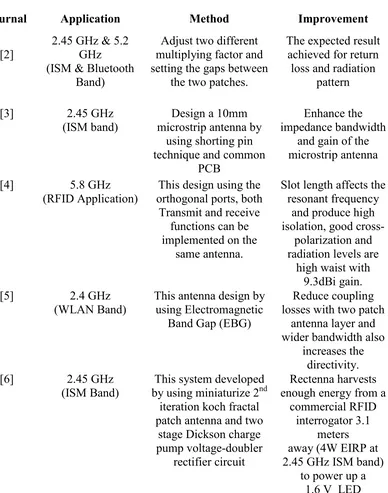
Table 2.1 summarizes the sample literature of reviewed journals.
Table 2.1: Summary of journals for literature review
Journal Application Method Improvement
[2] 2.45 GHz & 5.2 GHz
(ISM band) microstrip antenna by Design a 10mm using shorting pin
(RFID Application) orthogonal ports, both This design using the Transmit and receive
(WLAN Band) This antenna design by using Electromagnetic Band Gap (EBG)
9
2.3 Antenna Theory
An antenna is an electrical device which converts electric currents into radio wave or radio wave into electric currents. Antenna usually used with a radio transmitter or radio receiver. In transmission, radio transmitter applies an oscillating radio frequency electric current to the antenna‟s terminals and the antennas radiate the energy from the current as electromagnetic waves. Antennas that excite an electrical field are referred to as electrical antennas; antennas exciting a magnetic field are called magnetic antennas. The oscillating electrical or magnetic field generates an electromagnetic wave that propagates with the velocity of light, c. In reception, an antenna intercepts some of the power of electromagnetic waves in order to produce tiny voltage at its terminals. An antenna can be used for both transmitting and receiving. In other words, an antenna only converts an electromagnetic signal to an electrical signal at receiver or transmitter. If there is 100 % of efficiency, they radiate no more power than is delivered to their input terminal. This is because all the energy of the signal is absorbed.
2.4 Antenna Properties
There are many of basic properties that are used to describe the performance of the antenna. There are including impedance, return loss, VSWR, bandwidth, radiation pattern, 3 dB bandwidth, gain and polarization.
2.4.1 Impedance
10
Reflected waves will be generated at the antenna terminal and travel back towards the energy source if it does not match.
2.4.2 Return Loss
Return loss is a convenient way to characterize the input and output signals Sources. Return loss can be defined in dB as in the following equation (2.1);
RL (dB) = −20 log10 |Г| (2.1)
Where;
RL = return loss
Г = reflection coefficient
For perfect matching between the transmitter and the antenna, = 0 and RL = ∞
which means no power would be reflected back, whereas a = 1 has a RL = 0 dB, whichimplies that all incident power is reflected.
2.4.3 VSWR (Voltage Standing Wave Ratio)