Dual-Band M
H
Z. Zakaria, N. A. Zai
Centre of Telecommunication Research an Teknikal Malaysia Melaka (zahriladha
Abstract—A planar dual-band monopole an for Global System for Mobile Communicat applications, which also have the potential to harvesting system. The proposed antenna com plane at the back of the FR4 substrate and thr which are physically connected with each other of the substrate. The monopole antenna achiev at resonance frequencies of 915 MHz and bandwidth value of 124.2 MHz and 196.9 MH antenna gains of 1.97 dB and 3.05 dB are ach frequencies of 900 MHz and 1800 MHz. Ex show good agreement with simulated perform from the receiving antenna is also observed i the relationship of the power level and the transmitting and receiving antenna. This s investigation in designing the RF energy ha support green technology and sustaina particularly for Wireless Sensor Network (WSN
Keywords—Dual-band; monopole; GSM b gain
I. INTRODUCTION Energy harvesting or energy scavengin conversion process of the ambient energ energy. In recent years, there has been a grow deployment of wireless sensor networks (W in applications such as in structural m monitoring, healthcare systems and precision
However, the deployment of a large n nodes results in periodic battery replac impractical and costs consuming. One techn the aforementioned problems is to de comprising self-powered mechanisms th Frequency (RF) energy harvesting system significantly reduces the cost of replacing bat which also saves time.
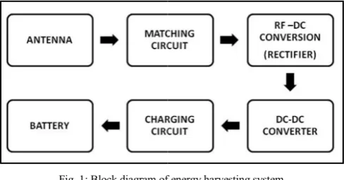
An energy harvesting system consis subsystems which are receiving antenna circuitry. Fig. 1 shows the basic block diag harvesting system.
Monopole Antenna For
Harvesting System
inuddin, M. Z. A. Abd Aziz, M. N. Husain, M. A
nd Innovation (CeTRI), Faculty of Electronic and Com(UTeM), Hang Tuah Jaya 76100, Durian Tunggal, Me
[email protected], [email protected]
ntenna is presented tions (GSM) band
be used for energy mprises of a ground ree microstrip lines r at the top surface ves good return loss 1800 MHz with a Hz respectively. The
hieved at resonance xperimental results mance. The output in order to analyze e distance between study is an early arvesting system to
able development N) applications.
band; return loss;
ng is basically a gy into electrical wing interest in the WSN) that are used
Fig. 1: Block diagram of
It has been reported that t areas may be as high as 0.5μW input power level of 16.6μW frequency [1]. Hence, an effor energy in the environment into many applications such as pow sensor networks or even to ch antenna is needed to transfer antenna captures the RF sig subsequently the rectifier circu those signals and convert them
It has been known that pla interesting physical features miniaturized, low cost and e planar monopole antennas are which is not only omnidirec dispersive [5].
Many efforts have been m shaped antennas which could p a number of planar mono geometries have been experim shorting post to the structure [1 to excite the antenna [15].
f energy harvesting system
the RF energy density in urban W/cm2. This corresponds to an W or -17.6dBm at 1800MHz
rt was made to convert the RF o electrical energy and use it for wering mobile devices, wireless harge batteries [4]. An efficient wireless power efficiently. The gnals from the ambient, and uit will extract the power from
into DC voltage.
anar monopole antennas present s such as simple structure, easy to fabricate. Additionally, e a compact broadband antenna ctional radiated, but also
non-made in order to obtain planar provide wider bandwidth. Hence,
pole antennas with different mentally characterized [6]-[11]. d antenna was achieved by hods [12],[13].
thods to improve the impedance g the geometry of the planar d. This includes of adding a 14] and using two feeding points
of planar dual band monopole trip lines structure for RF energy
integration with matching and rectifying circuit to generate DC power.
II. ANTENNA DESIGN
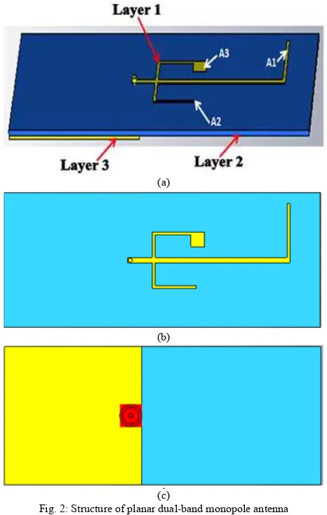
The geometry of this planar dual-band monopole antenna consists of a ground plane (Layer 3) on the back of the substrate (Layer 2) and three connected microstrip lines labeled as A1, A2 and A3 on top of the substrate (Layer 1). These three connected microstrip lines act as the planar-monopole structure and share the same feeding point with the coaxial cable connector.
The antenna was simulated in FR4 substrate with dielectric constant of 4.4 and thickness of 1.6mm. While the microstrip line and the ground plane used material from the copper annealed with thickness of 0.035mm. The geometry of the planar monopole antenna is shown in Fig. 2.
(a)
(b)
(c)
Fig. 2: Structure of planar dual-band monopole antenna (a) Perspective view (b) Front view (c) Back view
The lengths and geometries of the three connected microstrip lines can be optimized to provide the required impedances for two frequency bands operation. For instance, the central microstrip line, A1 can provide impedance of 50 ohms at the lower frequency of 915 MHz while the two side arms, A2 and A3 can be optimized to provide required
impedance for 1800MHz frequency band. The antenna’s dimensions are optimized by physical parametric studies.
III. EXPERIMENTAL RESULTS AND DISCUSSION The antenna is then fabricated in-house and the photograph of the prototype can be seen in Fig. 3. An experimental measurement also has been made to validate the simulation results.
(a) (b)
Fig. 3: Antenna prototype of planar dual-band monopole antenna (a) front view (b) back view
A. Return Loss, Bandwidth and Gain
S-parameter simulations of the antenna have been carried out using the Computer Simulation Tool (CST) 2011. Fig. 4 shows the simulated and measured return losses of the antenna.
Fig. 4: Simulation and measured return loss of planar dual-band monopole antenna
The measured return loss is in line with the simulation response where both manage to achieve lower than -10 dB. However, measurement result shows better return loss than the simulated one but the resonant frequencies were slightly shifted.
From the measured data, two resonant modes at about 912.5 MHz and 1.70 GHz are successfully achieved. Table 1 shows the comparison of simulation and measurement result for the planar dual-band monopole antenna.
Gain Received = PR– PT – GT + LP + LC1 + LC2 (1)
Where PR = power received; PT = power transmit; GT = gain transmit; LP = path loss; and LC = cable loss. The path loss is determined using Eq. 2.
LP = 32.45 + 20 log f (MHz) + 20 log d (km) (2) The variable f denotes the frequency of interest in MHz while d denotes the distance between transmitting and receiving antenna in kilometers.
TABLE I. SIMULATION AND MEASUREMENT RESULT OF PLANAR DUAL-BAND MONOPOLE ANTENNA
Freq. of interest
fr Return
Loss (dB)
Bandwidth
(MHz)
Gain
(dB)
915 MHz
Sim. 886 MHz
-27.54 102.7 1.97
Meas. 925 MHz
-30.06 124.2 -1.64
1800 MHz
Sim. 1.85 GHz
-15.96 236.1 3.05
Meas. 1.73 GHz
-25.50 196.9 0.85
The differences between simulation and measurement result are caused by the losses influenced by the distance, cables and connectors.
B. Radiation Pattern
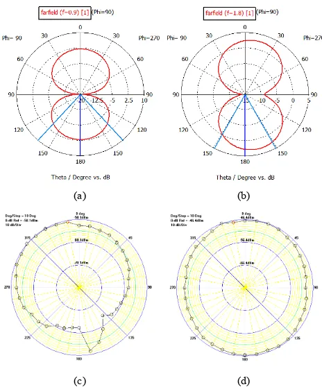
The radiation characteristics are also investigated and shown in Fig. 5.
(a) (b)
(c) (d)
Fig. 5: Antenna’s radiation pattern for (a) simulation at 900 MHz (b) simulation at 1800MHz (c) measurement at 900 MHz (d) measurement at
1800 MHz
The simulated radiation pattern indicates that the antenna radiates directionally while the measured radiation pattern is omnidirectional. The different patterns of simulation and measurement are observable and this might be caused by the environment around the antenna such as metallic influence which affected the measurement process.
C. Impedance Matching
The simulated impedance results are shown in Fig. 6. The planar dual-band monopole antenna shows impedance of 77.78-j9.01 Ω at 915 MHz and 38.27+j7.20 Ω at 1800MHz.
Fig. 6: Simulated impedance matching
It is observed that the antenna is not well matched to the 50 Ω impedance. However, a design of matching circuit can be proposed to match the impedance of the antenna with the rectifying circuit. This is to ensure the optimum power transfer can be delivered.
D. Surface Current
Fig. 7 shows the surface current of the dual-band monopole antenna.
(a)
(b)
From the figures, the current for lower frequency is radiated at A1 arm while A2 and A3 arm radiate the current for upper frequency.
E. Output Voltage and Output Power
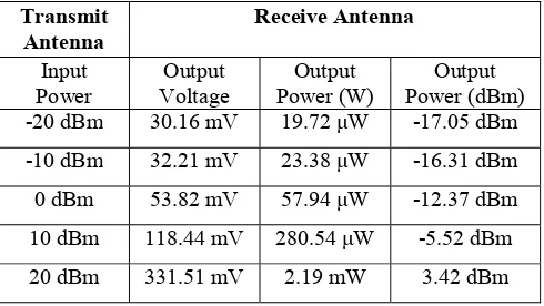
An experimental test has been conducted by varying the distance, D between the transmitting and receiving antenna. The input power of transmitting antenna is injected directly from a signal generator ranged from -20dBm to 20dBm. The output voltage and output power at the receiving antenna is then measured by using a spectrum analyzer.
Table II, Table III and Table IV show the output result from the receiving antenna based on different distances, D equal to 75, 50, and 25 cm. From these tables, it can be observed that the variation of distance and input power will affect the receiving antenna’s output. The output voltage and power increased when the distance, D of the transmitting and receiving antenna is reduced. The output voltage and power are also increased when the input power increased.
Hence, it can be concluded that the output voltage and output power is inversely proportional to the distance between transmitting and receiving antenna. However, the output voltage and output power is directly proportional to the input power.
This experimental work is an early effort done for the antenna of an energy harvester. The performance may be improvised by designing antennas with optimum performance to capture as much energy as possible and able to capture more energy even further. It is recommended to discover and design the most suitable antenna topology in order to produce better output.
IV. CONCLUSION
In this paper, the performance of a planar dual-band monopole antenna has been presented. The antenna operates at 915MHz and 1800MHz for GSM band application. The antenna’s measured return loss is better than the simulation value. However, the resonance frequencies are slightly shifted. Nevertheless, it is able to cover the frequency range of interest. The gain at 1800MHz is higher that the gain at 915MHz frequency. Hence, the antenna radiates well at 1800MHz frequency with an omnidirectional pattern compared to the radiation pattern at 915MHz. The measured antenna bandwidth at 915MHz represents 13.6% for ||S11|| ≤ 10dB, while the antenna bandwidth at 1800MHz represents 10.9% for ||S11|| ≤ 10dB. Future works can be done to improve the bandwidth of the antenna by increasing the substrate thickness or by adding parasitic elements. Additional microstrip lines at the antenna may be used to enhance it to a multiband antenna.
ACKNOWLEDGMENT
The authors would like to thank UTeM for sponsoring this work under the CoE, research grant UTeM, PJP/2012/CeTRI/Y00001.
REFERENCES
[2] M. Z. A. Abd Aziz, Z. Zakaria, M. N. Husain, N. A. Zainuddin, M. A. Othman, B. H. Ahmad, "Investigation of Dual and Triple Meander Slot to Microstrip Patch Antenna," Microwave Techniques (COMITE), pp. 36-39, 17-18 April 2013.
[3] Burch J. B. et al., “Radio Frequency Nonionizing Radiation in a Community Exposed to Radio and Televison Broadcasting”, Environmental Health Prospectives, vol. 114, no. 2, February 2006. [4] Penella M. T. et al., “Powering Wireless Sensor Nodes: Primary
Batteries Versus Energy Harvesting”, IEEE Instrumentation and Measurement Technology Conference, May 2009.
[5] Agrawall N. P., Kumar G., and Ray K. P., “Wideband Planar Monopole Antennas”, IEEE Trans. Antennas Propagation., vol. 46, pp. 294-295, February 1998.
[6] Ammann M. J., “Wideband Antenna for Mobile Wireless Terminal”, Microwave and Optical Technical Letters, vol. 26, no. 6, September 2000.
[7] Evans J. A., Ammann M. J., “Planar Trapezoidal and Pentagonal Monopoles with Impedance Bandwidths in Excess of 10:1”, IEEE Antennas and Propagation Society International Symposium, vol. 3, pp. 1558-1561, July 1999.
[8] Chen Z. N., “Impedance Characteristics of Planar Bow-Tie-Like Monopole Antennas”, Electronic Letters, vol. 36, no. 13, pp. 1100-1101, June 2000.
[9] Z. Zakaria, W.Y. Sam, M. Z. A. Abd Aziz and M. A. Meor Said, “Rectangular Microstrip Patch Antenna Based on Resonant Circuit Approach ” IEEE Symposium on Wireless Technology and Applications (ISWTA), pp.233-236, 2012.
[10] Z. Zakaria, W. Y. Sam, M. Z. A. Abd Aziz, A. Awang Md Isa, and F. Mohd Johar, “Design of Integrated Rectangular SIW Filter and Microstrip Patch Antenna”, IEEE Asia-Pacific Conference on Applied Electromagnetics (APACE), pp. 137-141, 2012.
[11] M. S. Mohamad Isa, R. J. Langley, S. Khamas, A. Awang Md Isa, M. S. I. M. Zin, F. M. Johar, and Z. Zakaria, "Antenna Beam Steering using Sectorized Square EBG," Journal of Telecommunication, Electronic and Computer Engineering (JTEC), vol. 4 No 1, pp. 39-44, 2012.
[12] Suh S. Y., Stutzman W. L., Davis W. A., “A New Ultrawideband Printed Monopole Antenna: The Planar Inverted Cone Antenna (PICA)”, IEEE Trans. Antennas Propagation, vol. 52, no. 5, pp. 1361-1364, May 2004.
[13] Kerkhoff A. J., Rogers R. R., Ling H., “Design and Analysis of Planar Monopole Antennas Using a Genetic Algorithm Approach,” IEEE Trans. Antennas Propagations, vol. 2, pp. 1768-1771, June 2004. [14] Ammann M. J., “Impedance Bandwidth of the Square Planar
Monopole”, Microwave and Optical Technical Letters, vol. 24, no. 3, February 2000.