! " #$ % & ' ( )
A Parametric Study on Dual Band Meander Line
Monopole Antenna For RF Energy Harvesting
Z. Zakaria1, N. A. Zainuddin2, M. Z. A. Abd Aziz, M. N. Husain, M. A. Mutalib
Faculty of Electronic & Computer Engineering, Universiti Teknikal Malaysia Melaka, Center for Telecommunication Research & Innovation (CeTRI)
Malacca, Malaysia
1
[email protected], [email protected]
—
! " # !
" $
% "
! " #
&' () *&"+& ,
% " &*- () $."+
() *."+' ,
% " " */00 ()"
! !
!
1 2 3 1 2 %
4 45 "
I. INTRODUCTION
Energy harvesting or energy scavenging is basically a conversion process of the ambient energy into electrical energy [1]. In recent years, there has been a growing interest in the deployment of wireless sensor networks (WSN) that are used in applications such as in structural monitoring, habitat monitoring, healthcare systems and precision agriculture.
However, the deployment of a large number of sensor nodes results in periodic battery replacements which is impractical and cost consuming. One technique to overcome the aforementioned problems is to deploy a network comprising self powered mechanism through a Radio Frequency (RF) energy harvesting system. This method significantly reduces the costs of replacing batteries periodically which also saves time.
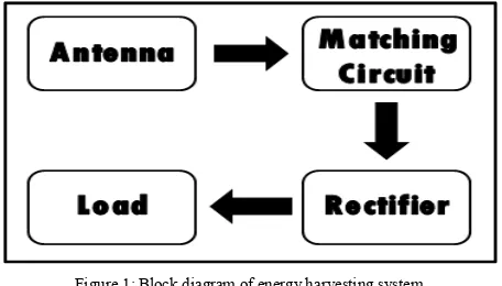
An energy harvesting system consists of two main subsystems which is receiving antenna and rectification circuitry. Fig. 1 below shows the basic block diagram of an energy harvesting system.
Figure 1: Block diagram of energy harvesting system
An efficient antenna is required to transfer wireless power efficiently. The antenna captures the RF signals from the ambient, and subsequently the rectifier circuit will extract the power from those signals and converts them into DC voltage.
Nowadays, electrically small, multiband antennas are widely used in the various communication systems. Typically, electrically small antenna has a low radiation efficiency and narrow bandwidth. To reduce the size of the antenna, a number of effective ways are possible to be done including by using high permittivity substrates [2] shorting pins [3][4] and meander line [5][6][7]. For GSM communication system, dual band antennas are required since the system operates at two frequencies which are at 915 MHz and 1800 MHz.
Meander line is a winding curve or bended line. Meander line technology allows the designers to design the antenna with a small size, but it provides overall wideband performance [8]. The Meander line could be in two different forms which are as meander strip lines (meander type patch) or as slotted meander lines. The meander line antenna is designed based on the wavelength of the desired frequency [9]. Having the advantage to miniaturize antenna, slotted meander line antenna is best chosen for antenna size reduction [10].
has been demonstrated in [2]. A meander conductor line is printed on a dielectric substrate to reduce the size of a monopole antenna, but the resulted antenna is only applicable for single band operation. Hence, the antenna has been enhanced so that it could operate for dual band applications. This can be achieved by extending a straight conductor line from the end of a rectangular meander monopole.
The proposed dual band monopole antenna is fed by a coplanar waveguide (CPW) line where the central conductor is separated from a pair of ground planes. The CPW offers several advantages including the ability to work at lower frequencies and ease of fabrication. The design of the meander line antenna has small dimension and approximately 50 D input impedance. The design begins with the electromagnetic (EM) simulations using Computer Simulation Tool (CST) software. The proposed dual band meander monopole antenna is designed to operate at 915 MHz and 1800 MHz as it approaches the GSM interoperability.
In this paper, a new class of dual band monopole antenna based on meandered microstrip lines structure for RF energy harvester is presented. Hence, the antenna can be recommended to integrate with matching and rectifying circuit to exhibits DC signals.
II. ANTENNA DESIGN
Fig. 2 shows the geometry of the proposed GSM dual band monopole antenna. This antenna is printed on an FR4 substrate with a thickness of 1.6 mm and relative permittivity of 4.4. A 50 D CPW transmission line is used to excite the antenna.
The basis of the antenna structure is a rectangular meander monopole, which has the dimensions of height 27mm and width 10.5 mm. A conductor line of height 25.5mm is extended from the end of the rectangular meander monopole. This extended conductor line is located relatively close to the rectangular meander monopole while the space between the two conductors is 1 mm.
Figure 2: Structure of dual band monopole antenna
In this design, the extended conductor line increases the current path of the antenna’s first resonant mode, which
reduces the required size of the proposed antenna for a fixed operating frequency. Moreover, as the two conductors are close to each other, the electromagnetic coupling is created between the two conductors, which leads to the second resonant mode excited with good impedance matching. That is by introducing the extend conductor line, the proposed compact dual frequency monopole antenna with good impedance matching can be obtained.
III. EXPERIMENTAL RESULTS AND ANALYSIS
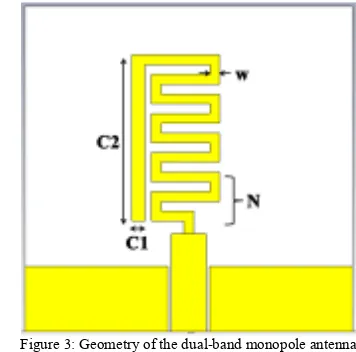
In order to provide an accurate antenna design, the investigation on the effects of physical dimension to the meander line has been conducted. The parameters of the meander line antenna that are considered in this paper are conductor line width (C1), conductor line length (C2), the number of turn (N) and meander line width (w) as shown in Fig. 3.
Figure 3: Geometry of the dual band monopole antenna
Table 1 shows the frequency response and return loss based on the effects of different conductor line width, (C1).
TABLE I. THE EFFECTS OF CONDUCTOR WIDTH (C1)
1 &*- () */00 ()
%
()
6 ,
%
()
6 ,
0.5 975 19.29 1850 11.27
1.5 957 18.13 1848 13.43
2.5 934 17.58 1837 14.12
3.5 915 15.32 1920 15.37
4.5 900 13.11 1920 17.48
! " #$ % & ' ( )
The effect of conductor length (C2) to the design is summarized in Table 2.
TABLE II. THE EFFECTS OF CONDUCTOR LENGTH (C2)
6 &*- () */00 ()
%
()
6 ,
%
()
6 ,
13.5 1306 19.34 2100 24.88
16.5 1215 17.89 1949 26.34
19.5 1135 17.23 1886 27.25
22.5 1051 15.47 1862 28.12
25.5 971 12.32 1802 29.75
The dual band monopole antenna shows that C2=25.5mm gives a return loss of 12.32dB at 971MHz while a return loss of 29.75dB is obtained at 1802MHz. It is observed that the frequency response of both frequencies shifts to lower frequency as the length of conductor line, C2 increases.
Table 3 shows the antenna performance based on number of turn, N. From the table, it can be observed that the number of turn, N = 4 produced the best return loss of 16.68dB at 910MHz and 16.38dB at 1732MHz respectively. The frequency response and return loss seems to be unstable when the number of turn is increased.
TABLE III. THE EFFECTS ON NUMBER OF TURN (N) 2
7
2
&*- () */00 ()
%
()
6 ,
%
()
6 ,
3 900 14.69 1680 14.39
4 910 16.68 1732 16.38
5 900 20.32 1692 19.57
6 880 10.08 1810 11.78
7 920 8.3 1762 15.42
The antenna’s performance is also affected by the meander line width and the analysis is shown in Table 4. The return loss doesn’t have any increment or decrement pattern but it varies according to the width of meander line.
In general, the responses of the antenna can be analyzed through the study as indicated in Table 1 – 4. The return loss decreases when the conductor width (C1) is increased. The same effect is experienced by the conductor length (C2), i.e. where the return loss decreased proportionally with the length of the conductor. However, this only occurred at lower frequency band.
Based on the analysis that has been studied, the dimension of the meander line antenna which operates at 915 MHz and 1800 MHz frequency can be optimized and determined as shown in Table 5.
TABLE IV. THE EFFECTS ON MEANDER LINE WIDTH (W)
&*- () */00 ()
%
() 6
,
%
() 6
,
0.5 867 12.34 1841 10.49
1.0 761 6.35 1666 9.14
1.5 970 8.74 1820 17.19
2.0 940 10.86 1467 12.23
2.5 974 11.94 1358 15.42
TABLE V. OPTIMUM PARAMETERS OF DUAL BAND MONOPOLE ANTENNA
8 6
Conductor width, C1 2
Conductor length, C2 25.5
Number of turn, N 4
Meander line width, w 1.5
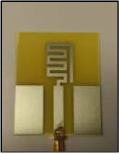
The antenna is then fabricated in house and the photograph of the prototype can be seen in Fig. 4. An experimental measurement also has been conducted to validate the simulation results.
Figure 4: Antenna prototype of dual band monopole antenna
Figure 5: Simulation and measured return loss of planar dual antenna
It is observed that the lower frequency measure well with the simulation and both results have a bandwidth. However, the bandwidth at the upper f narrower than the simulated result. The discrepanc the variation of permittivity in the substrate manufacturing tolerance. The small amounts of los to the losses from microstrip, copper loss through c and also losses through SMA connectors. Detaile frequency response, return loss, bandwidth an tabulated in Table 6.
TABLE VI. SIMULATION AND MEASUREMENT RESULT OF MONOPOLE ANTENNA From the measurement data, two resonant modes a MHz and 1800 MHz are successfully achieved.
The gain parameter is measured using the equation;
Gain Received = PR– PT – GT + PL + CL1 + C
where PR = power received; PT = power transmit
transmit; PL = path loss; and CL = cable loss.
The radiation characteristics are also investiga be seen in Fig. 6 below. The antenna radiates dire 915 MHz while the pattern is almost omnidirection MHz.
planar dual band monopole
ncy measurement agrees sults have a comparable t the upper frequency is he discrepancy is due to e substrate and also mounts of losses are due oss through conductivity nant modes at about 915
d using the following
+ CL2 (1)
wer transmit; GT = gain
lso investigated and can radiates directionally at omnidirectional at 1800
(a)
Figure 6: Simulated radiation pattern at (a)
Fig. 7 shows the surface current monopole antenna. The current for lower by the meander line and conductor line. at the CPW feeding line for upper freque line provides an additional resonant frequ conventional meander line monopole an operation.
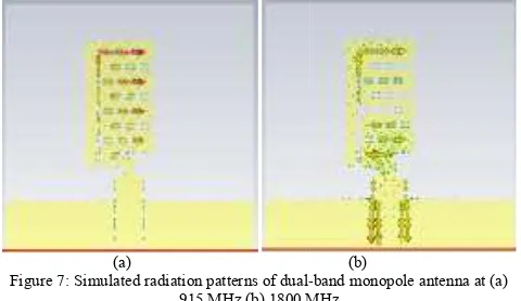
(a) Figure 7: Simulated radiation patterns of dual
915 MHz (b) 1800 MH
It is recommended in future works antenna to be further explored to be a harvesting. An experimental measuremen be conducted by varying the distance be and receiving antenna.
The input power of the transmitti injected directly from an RF signal gene 20dBm until 20dBm. The output voltage the receiving antenna is then can be spectrum analyzer. In this case, the perfo can be investigated in order to predic performance to capture as much energy suggested to discover and design the m topology for RF energy harvesting.
The antenna is then can be integrat convert the RF signals into the DC volta this system could be enhanced by em circuit to the rectifier for an improved ou test can also be conducted by varying th
(b)
ttern at (a) 915 MHz (b) 1800 MHz
rface current of the dual band rent for lower frequency is radiated onductor line. While current radiates or upper frequency. The conductor resonant frequency compared to a monopole antenna for a dual band
(b)
band monopole antenna at (a) 1800 MHz
uture works that for the designed ored to be applied on RF energy measurement in the laboratory can e distance between the transmitting
e transmitting antenna could be F signal generator ranged from utput voltage and output power at
en can be measured by using a ase, the performance of the antenna er to predict the most optimized uch energy as possible. Thus, it is design the most suitable antenna
! " #$ % & ' ( )
the transmitting and receiving antenna in future works. The input power of transmitting antenna can be injected directly from a signal generator ranged from 20dBm to 20dBm. The output voltage and output power at the receiving antenna is then can be measured by using a spectrum analyzer.
IV. CONCLUSION
In this paper, the performance of monopole dual band antenna has been presented. The antenna operates at 915 MHz and 1800 MHz for GSM band application. The antenna measurement return loss is better than the simulation value at the lower frequency. However, the resonance frequencies are slightly shifted. Nevertheless, it is able to cover the frequency of interest range. The gain at 1800 MHz is higher that the gain at 915 MHz frequency. Hence, the antenna radiates well at 1800 MHz frequency with an almost omnidirectional pattern compared to the radiation pattern at 915 MHz which is suitable for RF energy harvesting systems where it can receive the signal in 360°. Further works can be done to experimentally explore the designed antenna for RF energy harvesting systems.
ACKNOWLEDGMENT
The authors would like to thank Universiti Teknikal Malaysia Melaka (UTeM) for sponsoring this work under the research grant UTeM, PJP/2012/CeTRI/Y00001.
REFERENCES
[1] Z. Zakaria, N. A. Zainuddin, M. N. Husain, M. Z. A. Abd Aziz, M. A. Mutalib, A. R. Othman "Current Developments of RF Energy Harvesting
System for Wireless Sensor Networks ", AISS: Advances in Information Sciences and Service Sciences, Vol. 5, No. 11, pp. 328 338, 2013. [2] K. L. Wong, “Planar antennas for wireless communications”, Wiley
Interscience, 1st
edition, New York, 2003.
[3] S. C. Pan and K. L. Wong, “Dual Frequency Triangular Microstrip Antenna With A Shorting Pin”, IEEE Trans Antennas Propagation, pp. 1889 1891, 1997.
[4] Z. Zakaria, W.Y. Sam, M. Z. A. Abd Aziz and M. A. Meor Said, “Rectangular Microstrip Patch Antenna Based on Resonant Circuit Approach ” IEEE Symposium on Wireless Technology and Applications (ISWTA), pp.233 236, 2012.
[5] K. Noguchi et al, “A Study on Multiband Small Antennas Consisting of Multiple Conductors”, IEEE AP S International Symposium, pp. 124 128, July 1996.
[6] Y. D. Kim, H. Y. Kim and H. M. Lee, “Dual band LTCC chip antenna design using stacked meander patch for mobile handsets”, Microwave and Optical Technology Letters, Vol. 45, No. 5, pp. 271 273, May 2005.
[7] Choi, S. H., J. K. Park, S. K. Kim, and J. Y. Park, "A new ultra wideband antenna for UWB applications," Microwave and Optical Technology Letters, Vol. 40, 399 401, 2004.
[8] A. Khaleghi, A. Azooulay, J. C. Bolomey, “A Dual Back Couple Meandering Antenna For Wireless LAN Applications”, Gof Suryvette, France, 2005.
[9] D. Misman, I. A. Salamat, M. F. Abdul Kadir, M. R. Che Rose, M. S. R. Mohd Shah, M. Z. A. Abd Aziz, M. N. Husain, “The Effect of Conductor Line to Meander Line Antenna Design”, Journal of Telecommunication, Electronic and Computer Engineering (JTEC), vol. 1, no. 1, pp. 1 5, 2009.