Current Developments of RF Energy Harvesting System for Wireless
Sensor Networks
1
Zahriladha Zakaria,
1Nur Aishah Zainuddin,
1Mohd Nor Husain,
1Mohamad Zoinol Abidin
Abd Aziz,
1Mohamad Ariffin Mutalib,
1Abdul Rani Othman
1
Centre for Telecommunication Research and Innovation (CeTRI), Faculty of Electronic and
Computer Engineering, Universiti Teknikal Malaysia Melaka (UTeM), Hang Tuah Jaya,
76100 Durian Tunggal, Melaka, Malaysia
[email protected]
Abstract
Energy harvesting or energy scavenging is basically a conversion process of the ambient energy into the electrical energy. The ambient energy exists around us in many different forms including thermal, chemical, electrical and radio frequency (RF). This technique significantly reduces the costs of replacing batteries periodically. Hence, energy harvesting offers various environmental friendly alternative energy sources, which include the vibration, electromagnetic wave, wind energy and solar power. This study will focus on RF energy harvesting that involves the generating of a small amount of the electrical power to drive circuits in wireless communication electronics devices. Recently, wireless sensor network (WSN) has been a crucial part of our daily life. The importance of WSN can be described by the use of sensors in many devices for home security including light sensors, room thermostat and alarm systems. This paper presents an overview and the progress achieved in RF energy harvesting, which involves the integration of antenna with rectifying circuit. Different combinations of antenna and rectifier topologies yield diverse results. Therefore, this study is expected to give an indication on the appropriate techniques to develop an efficient RF energy harvesting system.
Keywords
: Antenna, Rectifier, Energy Harvesting, Wireless Sensor Network1. Introduction
In few years back, many new technologies have been applied in order to enhance our life quality. One of these technologies is the cost-saving system in a house which uses self-powered devices. For instance, Figure 1 shows a domestic lighting application which uses a sensor system to operate. The light is automatically turned on once the sensor detects a specific level of darkness in the room. The smart system not only offers a more comfortable living, but also a large scale of energy saving and a lower cost solution.
An energy scavenging method has been applied in small devices based on wireless sensor technology. For instance, battery-less remote control and mobile phone charger which operates using harvested energy is currently having a great demand from users since they contribute to reduce cost and saving time.
In recent years, there has been a growing usage of sensor-based wireless networks and applications which directly leads to the increased battery usage [2]. Until today, the limitation of energy supplies has become a crucial issue for the lifetime of these sensors since they operate on conventional batteries with a limited lifespan and fixed energy rate [3]. Furthermore, the deployment of a large number of sensor nodes results in periodic battery replacements which is impractical and cost-consumed [4].
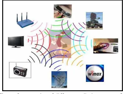
One of the solutions proposed to overcome these issues is to opt for energy harvesting [3]. Energy harvesting is mostly applied to enhance the efficiency of a system and to enable new technology. Harvesters utilize different radiating sources such as solar, motion and vibration, temperature scale and radio frequency, depending on their type. These different radiating sources are described as in Figure 2 [2] .
Figure 2. Examples of different radiating sources [2]
Similarly, the ambient energy can be extracted and converted into electrical energy that can be used to power up the sensors. Figure 3 shows the basic block diagram of RF-DC conversion system.
Figure 3. Basic block diagram of RF energy harvesting system
Despite the challenges possessed in RF energy harvesting [5], this system is still preferred due to the increasing availability of free RF energy from the advent of wireless broadcasting and communication systems.
The antenna is the key element of an RF energy harvesting system to capture the radiated RF energy and extract maximum power. The aim is to design antenna which can produce large DC output voltage. Until today, various antenna topologies have been recorded [3][4][6] for RF energy harvesting; nevertheless, only a few achieves a good performance in both gain and bandwidth.
Antennas can be designed in many forms, for instance patch antennas, dipole antennas, planar antennas, microstrip antennas and uniplanar antennas. Several types of patch antennas have been designed in various frequency regions focusing on bandwidth improvement [7]. Patch antenna with spiral structure [8] are also introduced where 3 types of spiral were compared to find the optimal structure.
Printed dipole antennas possess numerous advantages including low cost and large bandwidth. Therefore a dipole antenna was designed for optimum usage in GSM band applications [9]. Another antenna was designed for voltage boosting purposes in order to enhance DC output of RF energy harvesting system, specifically in a weak signal reception environment [10]. A study on improving antenna to exhibit dualband response for the energy harvesting application has been done in [11]. The other researchers are focused mainly on single band applications.
2. Energy harvesting system
An energy harvesting system consists of two main subsystems. The first one is the receiving antenna, which functions to capture ambient RF energy to power up the integrated embedded system. The second subsystem is the rectification circuitry, which converts the input RF power into DC output power efficiently.
The antenna captures the RF signals, and subsequently the rectifier circuit extracts the power of those signals and converts them into DC voltage. Therefore, an antenna with high efficiency is needed to transfer wireless power effectively.
2.1. Antenna Design
Recently, several efforts have been given to enhance the efficiency of the antenna in power scavenging [12][13]. Rectifying antenna, or literally called a rectenna, is one of the most important components in the wireless power transmission. It comprises a receiving antenna and a circuit which converts radio frequency to direct current (RF-DC) [14][15][16]. An efficient wireless power transmission system requires a rectenna with high RF-DC conversion efficiency. Several antenna topologies have been reported [5] for RF energy harvesting.
Most early research on radio frequency (RF) energy harvester designs focus on harvesting RF energy in a single RF band [17][18]. However, recently, there have been designs and implementations of a dual band [11] and triple band [19][6] antenna design for RF energy harvesting applications. The design of compact multiple band microstrip antennas for wireless applications also gains a highlight and received much attention in [20][21].
The planar monopole antenna is used to provide required impedance matching at two bands with easier integration [11]. The antenna consists of a ground plane on the back of the PCB, and three connected microstrip lines on the top of the PCB. All the microstrip lines shared the same feeding point with the RF input pin. The antenna was optimized by altering the length of the microstrip lines which also managed to provide required impedance. The same antenna structure with different antenna parameters was also designed. The purpose is to use the antenna for different implementations where Antenna A is for 900MHz & 1900MHz band application while Antenna B is for 900MHz & 2000MHz band application. Antenna B obtained better return loss with 35dB in comparison to Antenna A with -25dB of return loss. However, both antennas are still suitable to be adapted to general dual band applications which require a matching to different impedances at two frequencies.
Another study on dual band antenna has been done, but this time a microstrip patch was used [22]. The structure consists of a square-shaped ring patch and it is connected to a microstrip feedline. This antenna potentially work well with RF energy harvesting system due to its promising gain and bandwidth values. Furthermore, miniaturized microstrip antennas are able to improve their performance and reduce the overall size of wireless devices [27].
The study about ring patches proves that various ring shapes managed to obtain better bandwidth and higher radiation resistance when the higher order modes are excited [23][24][25]. Another different study found that the ring antenna is excited with a capacitive strip in another layer in a stacked configuration [26]. Paper [25] describes the impedance properties of a dual frequency concentric annular ring microstrip patch antenna. Meanwhile, a parametric study of a microstrip square ring antenna has been done in [22]. From the investigation, the bandwidth and gain of the microstrip square ring antenna increased with the increment the ring’s width even though the resonance frequency is slightly shifted to a lower frequency.
Printed dipole was also a type of antenna that was used for energy harvesting due to its advantageous features such as low cost and provide large bandwidth. In [9], printed dipole antenna is designed and optimized specifically for GSM band application at 915 MHz. This antenna yields a very omnidirectional radiation pattern which is very suitable for RF energy harvesting to capture signals in all directions. A mini reflector was used to triple up the gain of this antenna from 2.49 dB to 6.28 dB.
compared which are Archimedean spiral antenna, square spiral antenna and hexagonal spiral antenna as shown in Figure 4.
Figure 4. Array for (a) Hexagonal spiral antenna (b) Archimedean spiral antenna (c) Square spiral antenna [8]
Archimedean and square spiral antenna obtained better gain value than hexagonal spiral antenna with 5dB and 4.8dB, both at 2.4GHz frequency. However hexagonal spiral tends to approach the circular shape which optimizes the PCB cover area by accommodating a number of spirals. It also generates better broadband while maintaining packing conformality.
Patch antenna most likely has been chosen to be designed and implemented with RF energy harvesting. Various structures in the form of patch antennas have been designed such as L-shape, U-shape, star U-shape, E-U-shape, circular patch and square shaped to be used in the 900MHz, 2.4GHz, 4GHz, 5GHz, and 6GHz frequency [28][29][30][31]. Despite of its advantages of being low profile and inexpensive to fabricate, patch antennas has a drawback of narrow bandwidth, low efficiency, and low gain [7][4][19]. In order to overcome the problem, some methods have been investigated and proposed. These include embedding slots on the patch antenna and using various impedance matching and feeding techniques [32][33][34].
Antenna array design has also been investigated for RF energy harvesting with expectations to scavenge power effectively in [12][13]. Author of paper [4] proposed a microstrip stacked patch antenna array with lower power consumption. It shows better VSWR, return loss and efficiency compared to common inset fed patch antenna at 2.45 GHz frequency with improvement of return loss of about 30dB. Apart from that, the high gain value of 11.98 dB also was a factor that contributes to the antenna’s ability to achieve better voltage levels. However this antenna has a drawback of larger antenna size even though the use of antenna arrays can increase the RF and DC power [2]. A single patch itself has a dimension of 40.49mm x 40.49mm.
2.2. Rectifier Design
Rectifier, which is also called as pump device, has the function of converting an input RF signal received by the antenna into suitable DC supply voltage. Rectifier converts a part of the incoming power supply to DC for power supply. It takes advantage of the diode’s behavior to rectify a signal; depending on the signal level, the diode allows or does not allow the current to pass.
The basic or simplest rectifier consists of two different positions of the capacitor; parallel or series. Figure 5 (a) shows a rectifier using a series diode where the capacitor is connected in series followed by a parallel connected diode.
(a) (b) (c)
From the basic rectifier, a voltage doubler circuit can be designed by using two diodes and two capacitors as shown in Figure 5 (b). The voltage doubler configuration is chosen to be used as the rectifier circuit in [35] and [36]. Paper [37] has used conventional voltage doubler rectifier together with floating-gate voltage doubler rectifier. The function of voltage doubler rectifier is to rectify the full-wave peak-to-peak voltage of the incoming RF signal. It can be arranged in cascade to increase the output voltage.
Additional sections of diodes and capacitors may be cascaded in order to obtain voltage multiplier circuits of higher order. Voltage multiplier consists of N-stage which indicates the number of stages of particular voltage multiplier. Figure 5 (c) shows the design of a voltage multiplier.
The design of voltage multiplier circuit has been described in various literatures [38][39][40], for instance Cockroft Walton, Villard Cascade and Dickson voltage multiplier. Cockroft Walton voltage multiplier is capable to produce DC output voltage potential tens of times that of the peak AC input voltage. However, the drawback of this kind of rectifier is the limitation in current capacity and regulation. Table 1 shows the comparison of the rectifiers.
Table 1. Comparison of rectifiers Type of
rectifier
Structure Rectifier Topology
Basic rectifier A diode connected in series with a load. A capacitor acted as a filter to smoothen the ripple in the output. Commonly called as single-stage rectifier.
Half-wave rectifier, full-wave rectifier
Voltage doubler Uses two stages to approximately double up the DC voltage.
Converts RF energy into DC voltage using a network of capacitors and diodes.
Villard cascade voltage multiplier, Dickson multiplier, Cockroft Walton voltage multiplier
3. Discussion
The integration of the antenna and the rectifier is also known as rectenna. The rectenna is a passive element with a diode than can receive and rectify microwave power to direct current, which results in its ability to operate without any power source. Many research works on rectenna elements have been published. For example, the finding of various antenna types to be used in rectenna system such as dipole, Yagi-Uda antenna, microstrip antenna, monopole, coplanar patch, spiral antenna, and even parabolic antenna. The antennas can also be integrated with any type of rectify circuit (rectifier) such as single shunt full-wave rectifier, full-wave bridge rectifier, voltage multiplier and hybrid rectifiers. The circuit, especially the diode, determines the RF-DC conversion efficiency. Common diode used in most rectennas is silicon Schottky barrier diodes.
RF energy harvesting basically has several different types of system. In [2], two systems have been studied to recover the RF energy which is a broadband system and a narrowband system. For both systems, a broadband antenna is needed and therefore a spiral antenna is used. Unlike any spiral antenna structure in [8], an equiangular spiral antenna in [2] is used due to its advantageous features including possible dual polarization and its ability to operate under a broad frequency band.
In broadband system, it consists of rectifier without matching circuit and broadband antenna. Therefore the antenna used must be able to maximize the DC power harvested and recover all signals available. For that purpose, an omni-directional broadband antenna is needed. Return loss of the proposed antenna is lower than -10dB which means the efficiency of this antenna will be more than 90% overall. The antenna also managed to obtain a quasi omni-directional radiation pattern at a frequency of around 1GHz.
Another paper that is interested in spiral antenna as a receiver medium is stated in [37][38]. It presents a constant gain and input impedance in the interest band with circular polarization. The input recoverable power increases increasing the antenna gain. Antenna gain plays an important role on the RF to DC conversion efficiency. In addition, the antenna with directional radiation pattern contributes higher gain achievement, which eventually will increase the antenna’s receiving power. Therefore, most researchers use array and stacked patch antenna technique to increase the antenna gain, approximately until 10dB and above.
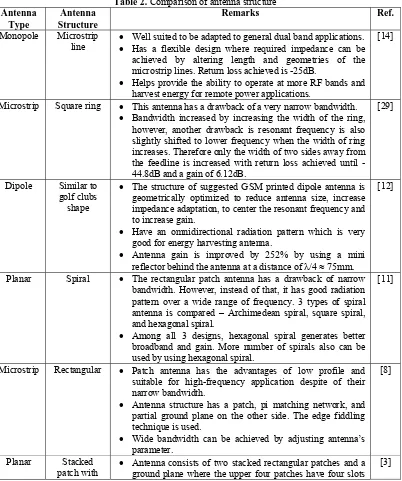
Several designs of antenna that are operate under a broad frequency band haven been identified from selected sources. These antennas have been redesigned and optimized using Computer Simulation Tool (CST). Some modifications have been made to the antenna structure to investigate the new outcome. Most of the antenna uses a FR-4 board material with different type such as microstrip, monopole, dipole and planar and embedded with various antenna structure as summarized in Table 2.
Table 2. Comparison of antenna structure
Antenna
Well suited to be adapted to general dual band applications. Has a flexible design where required impedance can be
achieved by altering length and geometries of the microstrip lines. Return loss achieved is -25dB.
Helps provide the ability to operate at more RF bands and harvest energy for remote power applications.
[14]
Microstrip Square ring This antenna has a drawback of a very narrow bandwidth. Bandwidth increased by increasing the width of the ring,
however, another drawback is resonant frequency is also slightly shifted to lower frequency when the width of ring increases. Therefore only the width of two sides away from the feedline is increased with return loss achieved until -44.8dB and a gain of 6.12dB.
[29]
Dipole Similar to golf clubs
shape
The structure of suggested GSM printed dipole antenna is geometrically optimized to reduce antenna size, increase impedance adaptation, to center the resonant frequency and to increase gain.
Have an omnidirectional radiation pattern which is very good for energy harvesting antenna.
Antenna gain is improved by 252% by using a mini reflector behind the antenna at a distance of /4 75mm.
[12]
Planar Spiral The rectangular patch antenna has a drawback of narrow bandwidth. However, instead of that, it has good radiation pattern over a wide range of frequency. 3 types of spiral antenna is compared – Archimedean spiral, square spiral, and hexagonal spiral.
Among all 3 designs, hexagonal spiral generates better broadband and gain. More number of spirals also can be used by using hexagonal spiral.
[11]
Microstrip Rectangular Patch antenna has the advantages of low profile and suitable for high-frequency application despite of their narrow bandwidth.
Antenna structure has a patch, pi matching network, and partial ground plane on the other side. The edge fiddling technique is used.
Wide bandwidth can be achieved by adjusting antenna’s parameter.
[8]
Planar Stacked patch with
Antenna consists of two stacked rectangular patches and a ground plane where the upper four patches have four slots
slots on the edges.
The antenna has a drawback in terms of size. It is bigger than other conventional antenna for RF energy harvesting. However, it has a very high gain value of 11.98dB. Microstrip Equiangular
spiral
For maximal power transfer, the antenna impedance must be matched to the optimal diode impedance for all frequencies.
Equiangular antenna has a possible dual polarization, broadband antenna and omni-directional radiation pattern.
[1]
There are a few requirements need to be considered when designing a rectifier circuit [41]. For instance, several criteria of rectifying circuit are evaluated in [42] including the choice of diodes, number of stages, effect of load impedance as well as the efficiency of RF-DC conversion.
We need to bear in mind that the most crucial requirement for a harvesting energy circuit is to be able to operate with weak input RF power. Therefore, a diode with a very fast switching time need to be used for the energy harvesting circuit is operating at high frequencies. Schottky diode is one of the popular diodes used in rectifier circuit. It uses a metal-semiconductor junction which allows the junction to operate much faster and gives forward voltage drop. Saturation current is another critical parameter that impacts the efficiency of diodes.
The number of rectifier stages has a major influence on the output voltage of the energy harvesting circuit where the output voltage is directly proportional to the number of stages used in the energy harvesting circuit. A rectifier with too few rectifier stages would yield an insufficient output voltage while too many rectifier stages may damp out the effect of the high Q-resonator. Figure 6 and Figure 7 shows the relation of number of rectifier stages on the energy harvesting efficiency and output voltage.
Figure 6. Effect of number of stages on the efficiency of energy harvesting circuit [42]
Figure 7. Effect of number of stages on the output voltage of energy harvesting circuit [42]
using any matching circuit while the second one is a narrowband system which includes a matching circuit.
The DC power scavenged using the narrowband system [2] can be attended until 400pW. The RF/DC converter used is a voltage doubler which uses the harmonic balance method. It was then optimized by using a commercial zero biased Schottky diode. Figure 8 shows the variations of the output DC power versus the input RF power at 1.5GHz which resulting the RF power more than -32dBm for both simulation and measurement.
Figure 8. Effect of load impedance on the efficiency of energy harvesting circuit [42]
Based on the review gained in this study, it is believed that there is still a room for further researches and developments before the technique become mature. Thus, it is recommended to further investigate and discover the optimum antenna and rectifier topology at GSM850, GSM900, GSM1800 and ISM frequency band particularly in Malaysia. It also involves designing several types of antennas to cover the above-mentioned frequency range in order to match the criteria for the overall system.
For the RF energy harvesting, the antenna with directional radiation pattern is most suitable to integrate with rectifying circuit because it radiates or receives more power in particular directions. However, antennas with an omnidirectional radiation pattern can still be considered since it provides and receives equal signals in all directions even though the signal strength might be weaker. Another factor to consider is to design an antenna with higher gain since the gain relates to the antenna’s ability to capture ambient signals significantly. Besides, the antenna itself must have a return loss better than -10 dB which contributes to 90% of antenna efficiency. Larger return loss indicates higher power being radiated by the antenna which eventually increases the antenna’s gain. Therefore, printed circuit board or PCB-based antenna will be used in this project since it is easy to fabricate, low cost and able to achieve high gain.
While the optimum rectifying circuit topologies must be comprehended to fulfill the requirement of supplying sufficient energy harvested and thus, it has been recognized that voltage multiplier is capable to realize a maximum conversion of RF signal into DC electrical signal.
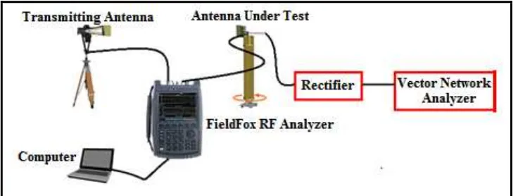
Figure 9. Antenna and rectifier measurement setup
4. Conclusion
A study on energy harvesting based on microwave signals has been reviewed. There are some design issues occurred in RF energy harvesting that need to be considered including low conversion efficiency and low rectified power. Improvements in efficiency of the RF signal harvesting is important. In general, many published papers on RF power to DC conversion - have presented circuits that are capable of converting input or incident power as low as -20dBm. This means that, if an RF survey or scan finds signals in space, with power spectrum levels around -20dBm, then it is potentially viable to harvest such signal power. The verification process of the proposed antenna and rectifier design that operates particularly in GSM and ISM band will be further explored and implemented through an experiment in laboratory and field works. It is believed that these discoveries will motivate further researches towards the usage of RF energy harvesting particularly in wireless sensor networks and their applications.
5. Acknowledgement
The authors would like to thank UTeM for sponsoring this work under the CoE, research grant UTeM, PJP/2012/CeTRI/Y00001.
6. References
[1] “Smart Homes and Home Automation by EnOcean.” [Online]. Available: http://www.enocean-alliance.org/en/smart-homes-residential-buildings/.
[2] Bouchouicha, D., F. Dupont, M. Latrach and L. Ventura, 2010. Ambient RF Energy Harvesting. International Conference on Renewable Energies and Power Quality, pp. 2–6.
[3] Sim, Z. W., R. Shuttleworth and B. Grieve, 2009. Investigation of PCB Microstrip Patch Receiving Antenna for Outdoor RF Energy Harvesting in Wireless Sensor Networks: 129–132. [4] Patel, A. C., M. P. Vaghela, H. Bajwa, and P. K. Patra, 2009. Power Harvesting for Low Power
Wireless Sensor Network: 633–636.
[5] Thomas, J. P., M. A. Qidwai, and J. C. Kellogg, 2006. Energy scavenging for small-scale unmanned systems. Journal of Power Sources, 159(2): 1494–1509.
[6] Arrawatia, M., M. S. Baghini, and G. Kumar, 2010. RF Energy Harvesting System at 2 . 67 and 5.8 GHz Microwave Conference Proceedings (APMC), 2010 Asia-Pacific, pp: 900–903.
[8] Devi, K. K. A., and S. Sadasivam, 2011. Design of a 377 Ω Patch Antenna for Ambient RF Energy Harvesting at Downlink Frequency of GSM 900. Communications (APCC), 2011 17th Asia-Pacific Conference, pp: 492–495.
[9] Mandal, S., and S. K. Giri, 2011. Comparison of antennas for Radio Frequency Energy Harvesting in 0.2–2.4 GHz range. 2011 3rd International Conference on Electronics Computer Technology, pp: 93–97.
[10] Alaeldine, A., M. Latrach, H. Raggad, and Z. Sayegh, 2011. Design and Optimization of a GSM Printed Dipole Antenna for Energy Harvesting Applications. 2011 IEEE International Symposium on Antennas and Propagation (APSURSI), pp: 1780–1783.
[11] Arai, H., M. Chomora, and M. Yoshida, 2012. A voltage-boosting antenna for RF energy harvesting. 2012 IEEE International Workshop on Antenna Technology (IWAT), pp: 169–172. [12] Shao, X., B. Li, N. Shahshahan, N. Goldsman, T. S. Salter, and G. M. Metze, 2011. A Planar
Dual-Band Antenna Design for RF Energy Harvesting Applications. Semiconductor Device Research Symposium (ISDRS), 2011 International, 41(1): 10–11.
[13] Pozar, D. M., 1992. Microstrip Antenna. Proceedings of The IEEE, 80(1) : 79–81. [14] Balanis, A., 2005. Antenna Theory, 3rd Edition. John Willey & Sons.
[15] Tsunayuki, Y., F. Kazuhiro, S. Minoru, and N. Shigeji, 2008. Design of RF-DC Conversion Circuit Composed of Chip Devices, Microwave Conference, 2008. APMC 2008. Asia-Pacific, pp: 1-4.
[16] Selvakumaran, W., W. Liu, H. S. Boon, M. Luo, and Y. L. Sum, 2009. Design of Low Power Rectenna for Wireless Power Transfer. TENCON 2009 – 2009 IEEE Region 10 Conference, IEEE Conferences, pp: 1-5.
[17] Georgiadis, A., G. Andia, and A. Collado, 2010. Rectenna Design and Optimization Using Reciprocity Theory and Harmonic Balance Analysis for Electromagnetic (EM) Energy Harvesting. Antennas and Wireless Propagation Letters, IEEE Journal, 2010, 9: 444-446.
[18] Umeda, T., 2006. A 950-MHz Rectifier Circuit for Sensor Network Tags With 10-M Distance. IEEE Journal of Solid-State Circuits, 41(1): 35-41.
[19] Salter, T., 2009. RF Energy Scavenging System Utilizing Switched Capacitor DC-DC Converter. Electronic Letters, 45(7): 374–376.
[20] Alkanhal, M. A. S., 2009. Composite Compact Triple Band Microstrip Antennas. Progress In Electromagnetics Research, 93: 221–236.
[21] Rowell, C. R., and R. D. Murch, 1998. A Compact PIFA Suitable for Dual-Frequency 900/1800 MHz Operation. IEEE Trans. Antennas Propagation, 46: 596-598.
[22] Sim, C. Y. D., 2007. A Novel Dual Frequency PIFA Design for Ease of Manufacturing Journal of Electromagnetic Waves and Applications, 21(3): 409-419.
[23] Behera, S., and K. J. Vinoy, 2009. Microstrip Square Ring Antenna For Dual-Band Operation. Progress In Electromagnetics Research, 63: 41–56.
[24] Mayhew-Rydgers, G., J. W. Avondale, and J. Joubert, 2000. New Feeding Mechanism for Annular-Ring Microstrip Antenna. Electronics Letters, 36: 605-606.
[25] Nurie, N. S., and R. J. Langley, 1990. Input Impedance of Concentric Ring Microstrip Antennas for Dual Frequency Band Operation Including Surface Wave Coupling. IEE Proceedings H Microwaves, Antennas and Propagation, 137(6): 331.
[26] Misra, I., S. K. Chowdhury, and S. Member, 1998. Study of Impedance and Radiation Properties of a Concentric Microstrip Triangular-Ring Antenna and Its Modeling Techniques Using FDTD Method, 46(4): 531–537.
[27] Latif, S. I., and L. Shafai, 2005. Dual-Layer Square-Ring Antenna (DLSRA) for Circular Polarization. 2005 IEEE Antennas and Propagation Society International Symposium, 2: 525–528. [28] Garg, R., P. Bhartia, I. J. Bhal, and A. Ittipiboon, 2001. Microstrip Antenna Design Handbook.
Artech House, Boston.
[29] Yang, F., S. Member, X. Zhang, X. Ye, and Y. Rahmat-samii, 2001. Wide-Band E-Shaped Patch Antennas for Wireless. Antenna and Propagation, IEEE Transaction, 49(7): 1094–1100.
[30] Chair, R., C. L. Mak, K. F. Lell, K. M. Luk, and A. Kishk, 2005. Miniature wideband half U-slot and half E-shaped patch antennas. IEEE Trans. Antenna Propagation, 53: 2645-2652.
[32] Bulja, S., 2006. Broadbanding Microstrip Antennas Using Unequal Patches, IEEE Antennas and Propagation Society International Symposium, pp: 3731–3734.
[33] Albooyeh, M., N. Kamjani, and M. Shobeyri, 2008. A Novel Cross-Slot Geometry To Improve Impedance Bandwidth of Microstrip Antennas. Progress In Electromagnetics Research Letters, 4: 63-72.
[34] Kasabegoudar, V. G., and K. J. Vinoy, 2009. A Broadband Suspended Micostrip Antenna for Circular Polarization. Progress In Electromagnetics Research, PIER 90: 353-368.
[35] Kordzadeh, A., and F. H. Kashani, 2009. A New Reduced Size Microstrip Patch Antenna With Fractal Shaped Defects. Progress In Electromagnetics Research B, 11: 29-37.
[36] Le, T., J. Han, A. V. Jouanne, K. Mayaram, and T. S. Fiez, 2003. Piezoelectric Power Generation Interface Circuits. Proceeding IEEE Custom Integrated Circuit Conference (CICC). San Jose, California, USA, pp: 489-492.
[37] Sivaramakrishnan A., and K. J. Jegadishkumar, October 2011. A Highly Efficient Power Management System for Charging Mobile Phones using RF Energy Harvesting, International Journal of Information Technology Convergence and Services (IJITCS) Vol.1, No.5, pp: 21–30. [38] Le, T., K. Mayaram, and T. S. Fiez, 2008. Efficient Far-Field Radio Frequency Energy Harvesting
for Passively Powered Sensor Networks. IEEE Journal of Solid-State Circuits, 43(5): 1287- 1302. [39] Minhong M., M. H Mickle, C. Capelli, and H. Swift, 2005. RF Energy Harvesting with Multiple
Antennas In The Same Space. IEEE Antennas and Propagation Magazine, 47(5): 100-106.
[40]Govardhani I., M. S. R. S Tejaswi, M. Venkata, N. Narayana, A. Babu., G. Anupama., and K. R. T. Venkata, 2011. Design of Coaxial Fed Microstrip Patch Antenna for 2.4 GHz Bluetooth Applications. Journal of Emerging Trends in Computing and Information Sciences, 2(12): 686-690. [41] Brown, W. C., 1984. The History of Power Transmission by Radio Waves. Microwave Theory and
Techniques, IEEE Transactions, 32(9): 1230-1242.
[42] Escala, O. A. C., 2010. Study of The Efficiency of Rectifying Antenna Systems for Electromagnetic Energy Harvesting. Degree. Thesis. Universidad Politecnica de Catalunya. Peru. [43]Tan T. D., Anh N. D., Thang C. M., Linh B. L. P., Quynh T. T. T., “ An Indoor Propagation Case
Study at Frequency 915 MHz”, IJEI: International Journal of Engineering and Industries, Vol. 3, No. 4, pp. 9 ~ 19, 2012.
![Figure 1. Energy harvesting wireless system in a smart house [1]](https://thumb-ap.123doks.com/thumbv2/123dok/554280.65268/1.595.164.437.550.693/figure-energy-harvesting-wireless-smart-house.webp)


![Figure 6. Effect of number of stages on the efficiency of energy harvesting circuit [42]](https://thumb-ap.123doks.com/thumbv2/123dok/554280.65268/7.595.181.420.375.508/figure-effect-number-stages-efficiency-energy-harvesting-circuit.webp)
![Figure 8. Effect of load impedance on the efficiency of energy harvesting circuit [42]](https://thumb-ap.123doks.com/thumbv2/123dok/554280.65268/8.595.176.423.181.320/figure-effect-load-impedance-efficiency-energy-harvesting-circuit.webp)