Corresponding Author: Zahriladha Zakaria, Centre for Telecommunication Research and Innovation (CeTRI), Faculty of Electronics and Computer Engineering, Universiti Teknikal Malaysia Melaka (UTeM), Hang
Hybrid Topology of Substrate Integrated Waveguide (SIW) Filter and Microstrip Patch
Antenna for Wireless Communication System
1
Zahriladha Zakaria,
1Sam Weng Yik,
1Mohamad Zoinol Abidin Abd Aziz,
2Kamaruzaman Jusoff,
1
Mohd Azlishah Othman,
1Badrul Hisham Ahmad,
1Mohamad Ariffin Mutalib and
3Shadia Suhaimi
1
Centre for Telecommunication Research and Innovation (CeTRI), Faculty of Electronics and
Computer Engineering, Universiti Teknikal Malaysia Melaka (UTeM), Hang Tuah Jaya 76100 Durian
Tunggal, Melaka, Malaysia
2
Perdana School of Science, Technology & Innovation Policy (UTM Perdana School), 6th Floor,
Menara Razak, Universiti Teknologi Malaysia Kuala Lumpur, Jalan Semarak, 54100 Kuala Lumpur,
Malaysia
3
Faculty of Business and Law, Multimedia University, Jalan Ayer Keroh Lama, 75450 Melaka,
Malaysia
Abstract: This paper presents an analysis based upon the resonant circuit approach to develop hybrid system for integrating a microwave filter and an antenna in a single device. This technique is used to reduce the overall volume of RF/ microwave front-end device especially in wireless communication systems. This study focuses on the hybrid of rectangular Substrate Integrated Waveguide (SIW) filter with rectangular microstrip patch antenna to produce filtering and radiating element in a single system. To prove the concept, the hybrid of microwave filter and antenna, the operating frequency of 2 GHz is demonstrated and validated through simulation and experimental. The experimental performance shows promising results which were in good agreement with the simulated results particularly in exhibiting return loss better than 10 dB in the passband region. This study is useful for any hybrid microwave system whereby it can reduce the complexity of the design, weight and cost as it is very important in base stations and multiplexer in any wireless communication systems.
Key words: Resonant circuit, Hybrid of microwave filters and antenna, Substrate Integrated Waveguide, Microstrip Patch Antenna
INTRODUCTION
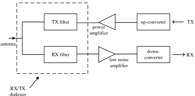
Communication systems in modern living are one of the important factors that influence our daily life whereby the systems use in communicating from one place to another place without moving to the particular place. This system has changed the human culture for decades. Without communication systems, human has difficulties to communicate with others that live far away from the rural/ urban area as shown in Figure 1. To improve the efficiency of communication systems, researchers have taken this opportunity to invent a better communication device that able to reduce size and cost of the end user. Most of the wireless products and services, for example, Global System for Mobile Communications (GSM), Long Term Evolution (LTE), Wireless Local Area Networks (WLANs), and satellite application use microwave devices, such as filter and antenna (Wu, W.J., et al., 2011; Hizan, H.M., et al., 2010; Potelon, B., et al., 2006). These wireless services provide end users with a better lifestyle in modern living without difficulty to access or communication with the each other.
Most of the wireless applications require better performance in term of data transmissions simple and small in size of the filter and antenna that can be implemented in devices. Basically, both filters and antennas are designed separately which are connected using external impedance as a connection. In order to get better performance, both filter and antenna systems need perfectly matched using suitable impedance matching for the both elements.
al., 2007; Lee, J.H., et al., 2007). However, the structure increases the overall size of physical layout, weight and losses.
Fig. 1: Some of the communication devices in modern daily life
TX filter
RX filter
power amplifier
low noise amplifier
up-converter
down-converter antenna
RX/TX diplexer
TX
RX
Fig. 2: Block diagram of a typical radio transceiver front end
In this paper, a hybrid device consisting of microwave filter and antenna based on the cascade and multilayer technique is demonstrated at the centre frequency approximately 2 GHz. The concept can then be proven and customized by researchers at any desired and appropriate frequency. The TE10 mode of propagation is used as a dominant mode to realize a single-mode of the microwave filter and antenna. The advantages of this technique are to realize of SIW filter and microstrip patch antenna that can be transformed for broadband applications and applied to hybrid topology between microwave filter and antenna.
Methods:
Ideal Circuit Design:
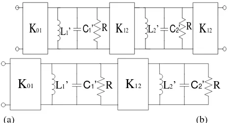
low-pass prototype circuit. The dual-mode rectangular SIW filter and rectangular microstrip patch antenna equivalent circuit.
It can also be developed based on a grouping of two single-mode equivalent circuit into one. One of the most important on designing the equivalent circuit of rectangular SIW filter and rectangular microstrip patch antenna is used to hybrid with any relevant equivalent circuit of filter with any suitable common impedance matching of 50 Ω in between two elements.
K
01L
1’
C
1’
R
K
12
R
C’
K
01L’
(a) (b)
Fig. 3: Single-mode circuit of (a) rectangular SIW filter and (b) rectangular microstrip patch antenna
K
01L
1’
C
1’
R
K
12L
2’
C
2’
R
K
12
R
C
1’
K
01L
1’
K
12L
2’
C
2’
R
(a) (b)
Fig. 4: Dual-mode circuit of (a) the rectangular SIW filter and (b) rectangular microstrip patch antenna
The impedance inverter Kr, r+1 and the capacitance Cr value of the low-pass prototype can be determined using [0]:
, (1)
where N, is the number of orders of the network andη, can be defined in (Hunter, I.C., 2001) and while is the ripple of insertion loss. The antenna equivalent circuit can be transformed from the low-pass prototype equivalent circuit using (Hunter, I.C., 2001):
, (2)
where is the geometric midband frequency; is the bandwidth scaling factor and the r is the number of orders.
Rectangular SIW Cavity:
Rectangular waveguide is commonly used in wireless communication systems which have the benefit of its high power handling capabilities and with low loss (Chuang, C.C., et al., 2007) but it gives disadvantages in term of size and high cost in manufacturing (Grubinger, H., et al., 2009). Therefore, SIW filter is applied on the rectangular waveguide so it can hybridize with any planar structure (Liu, J., et al., 2012). SIW is an artificial waveguide which is constructed on a planar substrate with periodic arrays of metalized via holes inside the cavity (Deslandes, D. and W. Ke, 2002).
(3)
TE10 mode is the efficient width of and length, of the resonant SIW cavity is given by (Deslandes, D. and W. Ke, 2002; Zakaria, Z., et al., 2012). The width and length of the resonant SIW cavity, d
and p are the diameter and the distance between adjacent vias can be calculated using the design rules from (Zakaria, Z., et al., 2012; Li, R.Q., et al., 2010; Chen, X., et al., 2012).
Rectangular Microstrip Antenna:
The rectangular microstrip patch antenna will be used in the integration with the rectangular SIW filter for its desirable features such as light weight and low profile. The layout of the antenna can be easily calculated by the width and the length of its dimensions (Constantine A.B., 2005) and (Zakaria, Z., et al., 2012).
Hybrid Topology of SIW Filter and Microstrip Antenna:
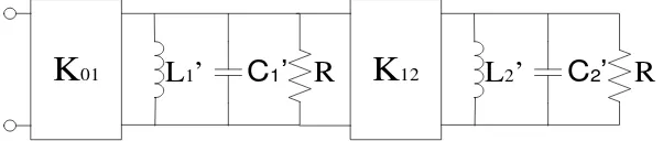
The hybrid topology of the equivalent circuit of the rectangular SIW filter and rectangular microstrip patch antenna can be designed in a cascade and multilayer structures as shown in Figure 5. The transformation of the rectangular SIW filter and rectangular microstrip patch antenna is equivalent to physical circuit layout as shown in Figure 6. The multilayer structure has the benefit of direct coupling without additional matching impedance between the filter and antenna as well as size reduction compared with the cascaded structure. Figure 7 shows the measurement setup on the Device Under Test (DUT) using the Vector Network Analyzer (VNA).
R
C1’
K
01L
1’
K
12L
2’
C2’
R
Fig. 5: Hybrid topology of equivalent circuit for cascade and multilayer between the rectangular SIW filter and rectangular microstrip patch antenna for single-mode
(a) (b)
Fig. 6: (a) Cascade and (b) multilayer approach between rectangular SIW filter and rectangular microstrip patch Antenna
RESULTS AND DISCUSSION
Single-Mode Filter and Antenna:
The single-mode rectangular SIW filter and microstrip patch antenna equivalent circuit has been designed at 2 GHz to obtain the coupling value, K01 = K12 = 50, capacitance, C’ = 98.98 pF and inductance, L’ = 63.98 pH for rectangular SIW filter meanwhile for microstrip patch antenna, the coupling value, K01 = 50, capacitance, C’ = 98.98 pF and inductance, L’ = 63.98 pH. The layout design of the rectangular SIW filter and microstrip patch antenna is simulated using CST Microwave Studio software. The devices are constructed using based on FR-4 material.
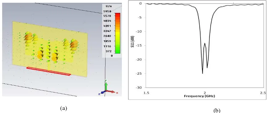
The Electromagnetic (EM) of Electric field (E-field) for the TE10 mode of the SIW filter at 2 GHz is shown in Figure 8 (a). The simulations show the magnitude of E-field is concentrated in the center of SIW cavity. The array of via-holes of the SIW cavity is used as a wall to prevent the EM fields leak from the SIW cavity. Figure 8 (b) shows the simulated and measured results on the rectangular SIW filter. The physical length, and width, of SIW filter are 48.75 mm and 51.62 mm, whilst the via-hole diameter, d = 1 mm and the pitch, p = 3 mm respectively.
The E-field for TE10 mode on rectangular microstrip patch antenna at 2 GHz are shown in Figure 9 (a). There is a noted less concentration of the E-field in the rectangular patch antenna cavity due to the fact that the microstrip patch antenna is a radiating element. Figure 9 (b) shows the simulated and measured results on the rectangular microstrip patch antenna.
(a) (b)
Fig. 8: E-field distribution of rectangular SIW filter in single mode (TE10) at 2 GHz (b) Simulated and measured results of rectangular SIW filter
(a) (b)
Fig. 9: E-field distribution for rectangular microstrip patch antenna in single mode (TE10) at 2 GHz (b) Simulated and measured results on rectangular microstrip patch antenna
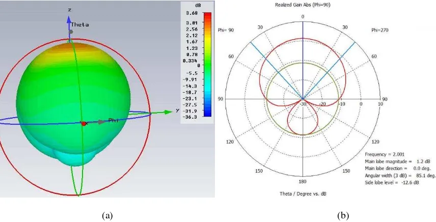
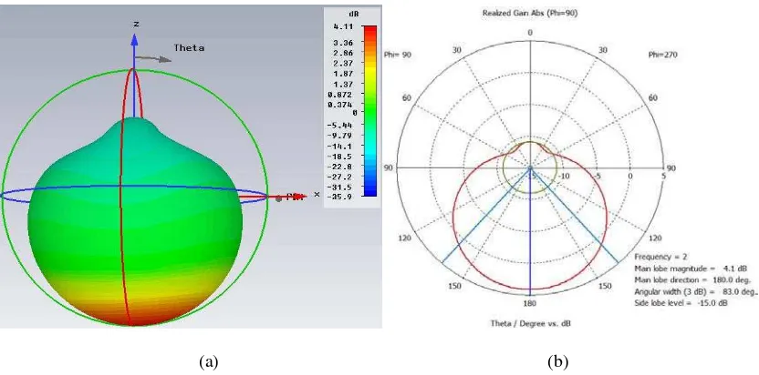
cascaded structure in three dimensional at 2 GHz. The main and side lobes can be observed in simulated two dimensional radiation pattern as shown in Figure 11 (b). The pattern represents the main lobe magnitude of 1.0 dB at 0.0 degree direction from the origin point.
(a) (b)
Fig. 10: (a) E-field distribution at 2 GHz (b) Simulated and measured results for hybrid rectangular SIW filter and rectangular microstrip patch antenna
The design is then carried out on the simulation multilayer structure for microwave filter and antenna as shown in Figure 12 (a). The return loss of -24.65 dB and bandwidth of 62.98 MHz is achieved especially in the passband as shown in Figure 12 (b). The simulated far-field radiation pattern as shown in Figure 13 (a) indicates the forward directional pattern of the multilayer structure in three dimensional at 2 GHz. The main and side lobes can be observed in simulated two dimensional radiation pattern as shown in Figure 13 (b). The pattern represents the main lobe magnitude of 4.1 dB at 180.0 degree direction from the origin point.
(a) (b)
(b)
Fig. 12: (a) Multilayer structure between SIW filter and microstrip patch antenna (b) Simulated on multilayer rectangular SIW filter and rectangular microstrip patch antenna designed at 2 GHz
(a) (b)
Fig. 13: Simulated (a) three dimension and (b) two dimension radiation pattern of the multilayer structure designed at 2 GHz
Dual-Mode Filter and Antenna:
The study explored by analyzing dual-mode topology for microwave filter and antenna through the simulation. The design value for coupling value, K01 = K23 = 50; K12 = 59.85 capacitance, C1’ = C2’ = 42.56 pF and inductance, L1’ = L2’ = 149.23 pH. The layout design on the dual-mode (TE20 mode of propagation) of the SIW cavity filter with EM fields at 2 GHz is shown in Figure 14 (a). The electromagnetic field analysis shows that the distribution of E-fields with two circular propagating is observed in the single SIW cavity filter. Figure 14 (b) shows the simulation results of the dual-mode SIW cavity filter. The return loss (S11) and insertion loss (S21) of about -17 dB and -1 dB with a bandwidth of around 195 MHz have been obtained.
(b)
Fig. 14:(a) E-field distribution of rectangular SIW filter in dual-mode at 2 GHz (TE20) (b) Simulation results on dual-mode rectangular SIW filter
As for the dual-mode antenna, investigation of the EM field pattern behavior at 2 GHz is shown in Figure 15 (a). In this topology, a perturbation notch is introduced in order to separate two orthogonal modes in the rectangular microstrip patch antenna cavity. Figure 15 (b) shows the simulated results of the dual-mode antenna.
(b)
Fig. 15: (a) E-field distribution for rectangular microstrip patch antenna in dual-mode (TE20) at 2 GHz (b) Simulation results on dual-mode rectangular microstrip patch antenna
The analysis is then carried out on the proposed dual-mode cascaded hybrid in between microwave filter and antenna. The design value for coupling value, K01 = K34 = 50; K12 = K45 = 55.28, capacitance, C1
’
= C2’ = 42.43 pF; C3’ = C4’ = 38.58 pF and inductance, L1’ = L2’ = 149.22 pH; L3’ = L4’ = 135.65 pH based on Figure 16. The simulated results of equivalent circuit for cascaded integration gives the return loss, S11, with better than -12 dB with bandwidths of around 95 MHz have been achieved. The electromagnetic field’s pattern for the dual-mode cascaded hybrid rectangular SIW filter and rectangular microstrip patch antenna at 2.1115 GHz are shown in Figure 17 (a). The S-parameter response of the integrated filter and antenna is shown in Figure 17 (b). It shows that the return loss (S11) with better than -20 dB with a bandwidth of around 48.95 MHz and 57.00 MHz have been achieved.
(a)
R
C1’
K
01 L1’K
12 L2’ C2’ RK
34 L3’ C3’ RK
45 L4’ C4’ RFig. 16: Cascaded hybrid in between the rectangular SIW filter and rectangular microstrip patch antenna
(a) (b)
Fig. 17:(a) E-field distribution for dual-mode cascaded hybrid topology at 2.1115 GHz (b) Simulation result of cascaded hybrid rectangular SIW filter and rectangular microstrip patch antenna in dual mode
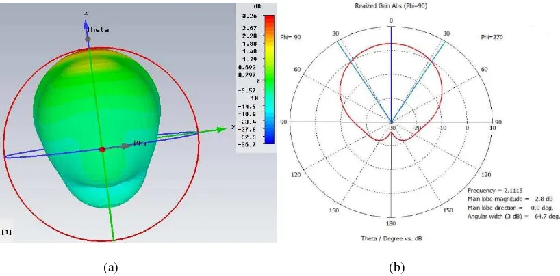
The simulated far-field radiation pattern as shown in Figure 18 (a) indicates the forward directional pattern of the dual-mode cascade structure in three dimensional. The main and side lobes can be observed in simulated two dimensional radiation pattern as shown in Figure 18 (b). The pattern represents the main lobe magnitude of 5.0 dB at 1.0 degree direction from the origin point at frequency 2.1115 GHz. The frequency was selected for radiation pattern due to the responsiveness of the return loss has better than -20 dB. Table 1 shows a summary of the simulation and measurement results for single- and dual-mode structures.
(a) (b)
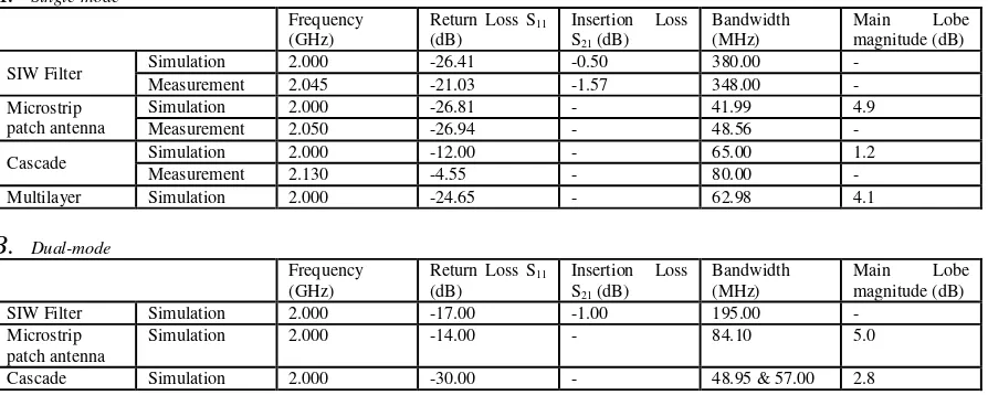
Table 1: Summary of simulation and measurement results
A.
Single-modeFrequency (GHz)
Return Loss S11
(dB)
Insertion Loss S21 (dB)
Bandwidth (MHz)
Main Lobe magnitude (dB)
SIW Filter Simulation 2.000 -26.41 -0.50 380.00 - Measurement 2.045 -21.03 -1.57 348.00 - Microstrip
patch antenna
Simulation 2.000 -26.81 - 41.99 4.9
Measurement 2.050 -26.94 - 48.56 -
Cascade Simulation 2.000 -12.00 - 65.00 1.2
Measurement 2.130 -4.55 - 80.00 -
Multilayer Simulation 2.000 -24.65 - 62.98 4.1
B.
Dual-modeFrequency (GHz)
Return Loss S11
(dB)
Insertion Loss S21 (dB)
Bandwidth (MHz)
Main Lobe magnitude (dB) SIW Filter Simulation 2.000 -17.00 -1.00 195.00 -
Microstrip patch antenna
Simulation 2.000 -14.00 - 84.10 5.0
Cascade Simulation 2.000 -30.00 - 48.95 & 57.00 2.8
Conclusion:
In this paper, the realization of hybrid topology of rectangular SIW filters and rectangular microstrip patch antenna has been successfully presented. A new topology technique to produce single and dual-mode of the rectangular SIW filter and rectangular microstrip patch antenna based on resonant circuit approach has been developed. The experimental results of the cascaded integration are in-line with the simulated responses. The multilayer integration between the rectangular SIW filter and rectangular microstrip patch antenna was simulated to reduce the overall physical volume significantly. Further investigations on multilayer structure will be conducted in future works in order to analyze and characterize the performance of such integration to produce a new class of integrated filter and antenna in a multilayer structure. This new hybrid topology is useful to produce filtering and radiating element in a single device and recommended to be applied in microwave RF front systems where the reduction of overall physical volume and cost is very important.
ACKNOWLEDGEMENT
The authors would also like to thank UTeM and MyBrain15 for sponsoring this work under the short-term grant UTeM PJP/2012/FKEKK (15B)/S01019.
REFERENCES
Chen, X., W. Hong, T. Cui, Z. Hao and W. Ke, 2005. Substrate Integrated Waveguide Elliptic Filter With Transmission Line Inserted Inverter. Electronics Letters, 41(15): 851- 852.
Chuang, C.C., H.H. Lin and C.L. Wang, 2007. Design of Dual-Mode SIW Cavity Filters. TENCON 2007 - 2007 IEEE Region 10 Conference, pp: 1-4.
Constantine A.B., 2005. Antenna Theory: Analysis and Design 3rd edition, John Wiley and Sons, Inc. Deslandes, D. and W. Ke, 2002. Design Consideration and Performance Analysis of Substrate Integrated Waveguide Components. Microwave Conference, pp: 1-4.
Grubinger, H., H. Barth and R. Vahldieck, 2009. An LTCC-based 35-GHz Substrate-Integrated-Waveguide Bandpass Filter. Microwave Symposium Digest, 2009 MTT '09. IEEE MTT-S International, pp: 1605-1608.
Hizan, H.M., I.C. Hunter and A.I. Abunjaileh, 2010. Integrated SIW Filter and Microstrip Antenna. Microwave Conference (EuMC) 2010 European, pp: 184-187.
Hunter, I.C., 2001. Theory and Design of Microwave Filters, The Institution of Electrical Engineers. Lee, J.H., N. Kidera, S. Pinel, J. Laskar and M.M. Tentzeris, 2007. Fully Integrated Passive Front-End Solutions for a V-band LTCC Wireless System. Antennas and Wireless Propagation Letters, IEEE, 6: 285-288.
Li, R.Q., X.H. Tang and F. Xiao, 2010. Substrate Integrated Waveguide Dual-Mode Filter Using Slot Lines Perturbation. Electronics Letters, 46(12): 845-846.
Liu, J., D.R. Jackson and Y.L. Long, 2012. Substrate Integrated Waveguide (SIW) Leaky-Wave Antenna with Transverse Slots. Antennas and Propagation, IEEE Transactions, 60(1): 20-29.
Nova, O.A., J.C. .M. Peña, 2011. An Approach To Filter-Antenna Integration in SIW Technology. Circuits and Systems (LASCAS), IEEE Second Latin American Symposium, pp: 1-4.
Potelon, B., J.C. Bohorquez, J.F. Favennec, C. Quendo, E. Rius and C. Person, 2006. Design of Ku-Band Filter based on Substrate-Integrated Circular Cavities (SICCs). Microwave Symposium Digest, 2006. IEEE MTT-S International, pp: 1237-1240.
Roubat, M., S. Bila, M. Thevenot, D. Baillargeat, T. Monediere, S. Verdeyme and B. Jecko, 2007. Mutual Synthesis of Combined Microwave Circuits Applied to the Design of a Filter-Antenna Subsystem. Microwave Theory and Techniques, IEEE Transactions, 55(6): 1182-1189.
Wu, W.J., Y.Z. Yin, S.L. Zuo, Z.Y. Zhang and J.J. Xie, 2011. A New Compact Filter-Antenna for Modern Wireless Communication Systems. Antennas and Wireless Propagation Letters, IEEE, 10: 1131-1134.
Zakaria, Z. and B.H. Ahmad, 2011. Design of SIW Bandpass Filter with 6 dB Offset. RF and Microwave Conference (RFM). 2011 IEEE International, pp: 87-90.
Zakaria, Z., W.Y. Sam, M.Z.A. Abd Aziz and M.A. Meor Said, 2012. Microwave Filter and Antenna for Wireless Communication Systems. 2012 IEEE Symposium on Wireless Technology and Applications (ISWTA), pp: 76-81.