i
INVESTIGATION OF RECEIVING ANTENNA FOR ENERGY SCAVENGING FROM MICROWAVE SIGNAL
MOHD SHAIKHUL KHALID BIN ABDULLAH
This report is submitted in partial fulfillment of requirement for the Bachelor Degree of Electronic Engineering (Telecommunication Engineering)
Fakulti Kejuruteraan Elektronik dan Kejuruteraan Komputer (FKEKK) Universiti Teknikal Malaysia Melaka (UTeM)
ii
UNIVERSTI TEKNIKAL MALAYSIA MELAKA
FAKULTI KEJURUTERAAN ELEKTRONIK DAN KEJURUTERAAN KOMPUTER
BORANG PENGESAHAN STATUS LAPORAN
PROJEK SARJANA MUDA II
Tajuk Projek : INVESTIGATION OF RECEIVING ANTENNA FOR ENERGY SCAVENGING FROM MICROWAVE SIGNAL
Sesi
Pengajian : 1 3 / 1 4
Saya MOHD SHAIKHUL KHALID BIN ABDULLAH
mengaku membenarkan Laporan Projek Sarjana Muda ini disimpan di Perpustakaan dengan syarat-syarat kegunaan seperti berikut:
1. Laporan adalah hakmilik Universiti Teknikal Malaysia Melaka.
2. Perpustakaan dibenarkan membuat salinan untuk tujuan pengajian sahaja.
3. Perpustakaan dibenarkan membuat salinan laporan ini sebagai bahan pertukaran antara institusi pengajian tinggi.
4. Sila tandakan ( √ ) :
SULIT*
*(Mengandungi maklumat yang berdarjah keselamatan atau kepentingan Malaysia seperti yang termaktub di dalam AKTA RAHSIA RASMI 1972)
TERHAD** **(Mengandungi maklumat terhad yang telah ditentukan oleh organisasi/badan di mana penyelidikan dijalankan)
TIDAK TERHAD
Disahkan oleh:
__________________________ ___________________________________
(TANDATANGAN PENULIS)
Tarikh: ………
iii
“I hereby announce that this thesis entitled, Investigation of Receiving Antenna for Energy Scavenging from Microwave Signal is a consequence of my own research
idea concept for works that have been cited clearly in the references.”
SIGNATURE: ………... NAME: MOHD SHAIKHUL KHALID BIN ABDULLAH
iv
“I, hereby declare that I have read this report and in my opinion, this report is sufficient in terms of scope and quality for the award of Bachelor of Electronic
Engineering (Telecommunication Engineering) with Honors.”
SIGNATURE: ……….. NAME: DR. ZAHRILADHA BIN ZAKARIA
v
vi
ACKNOWLEDGEMENT
First and foremost, I would like to express my gratitude to my dedicated and supportive supervisor, Dr. Zahriladha Bin Zakaria for providing his insightful knowledge and valuable assistance throughout the culmination and success of this project under his guidance.
A particular line of appreciation is extended to my parents, for their unflagging encouragement and financial funding that they have devoted to me for over the years. Their support and encouragement is one of the primary reasons of the success I gain.
Thanks as well to all my acquaintances for their counsel and knowledge they provide to me. My thanks as well extend to all who support me directly and indirectly in making out this task.
vii
ABSTRACT
viii
ABSTRAK
ix
TABLE OF CONTENT
CHAPTER TITLE PAGE
PROJECT TITLE i
REPORT STATUS VERIFICATION FORM ii
STUDENT’S VERIFICATION iii
SUPERVISOR’S VERIFICATION iv
DEDICATION v
ACKNOWLEDGEMENT vi
ABSTRACT vii
TABLE OF CONTENT viii
LIST OF FIGURES xii
LIST OF TABLES xiv
1 INTRODUCTION
1.1 Introduction 1
1.2 Objective 2
1.3 Problem Statement 3
1.4 Scope of Work 4
1.5 Methodology 5
1.6 Contribution of Project 7
2 LITERATURE REVIEW
2.1 Introduction 8
2.2 Critical Literature Review 8
2.3 Antenna Theory 10
2.4 Antenna Properties 10
2.4.1 Impedance 11
x
2.4.3 VSWR (Voltage Standing Wave Ratio) 11
2.4.4 Bandwidth 12
2.4.5 Radiation pattern 13
2.4.6 Gain 13
2.4.7 Polarization 13
2.4.7.1 Types of polarization 15 2.5 Circularly Polarized Microstrip Patch Antenna 18
2.6 Microstrip Antenna 20
2.6.1 Metallic patch 20
2.6.2 Dielectric substrate 21
2.6.3 The ground 21
2.6.4 Feeding 22
2.6.4.1 Coaxial feeding 22 2.6.4.2 Microstrip feeding 23 2.6.4.3 Proximity coupled feeding 24 2.6.4.4 Aperture – coupled feeding 25 2.7 Advantages and Disadvantages of Microstrip
Antenna 26
2.8 Methods of analysis 27
2.9 Conclusion 28
3 METHODOLOGY
3.1 Introduction 29
3.2 Antenna Specification 32
3.3 Antenna Design 34
3.3.1 Rectangular patch antenna 34 3.3.2 Transmission line for array patch antenna 35 3.3.3 Feeding of array patch antenna 36 3.4 Design Parameter of Rectangular Array Antenna 37 3.5 Design of the Rectifying Circuit 39
3.6 Fabrication Process 40
xi
3.7.3 Power receiver for antenna 43 3.7.4 Output voltage for the antenna with rectifier
circuit 44
3.8 Conclusion 46
4 RESULT AND DISCUSSION
4.1 Introduction 47
4.2 Result for antenna 47
4.3 Simulation Result for Antenna 48
4.2.1 Return loss 48
4.2.2 Gain 49
4.2.3 Radiation pattern and directivity 50 4.2.4 Impedance matching 51 4.3 Measurement Result of the Antenna 52
4.3.1 Return loss 52
4.3.2 Gain 53
4.3.3 Radiation pattern 56
4.4 Conclusion 57
5 CONCLUSION AND RECOMMENDATION
5.1 Introduction 58
5.2 Conclusion 58
5.3 Recommendation 59
xii
LIST OF FIGURE
FIGURE TITLE PAGE
1.1 RF energy harvesting block diagram 2
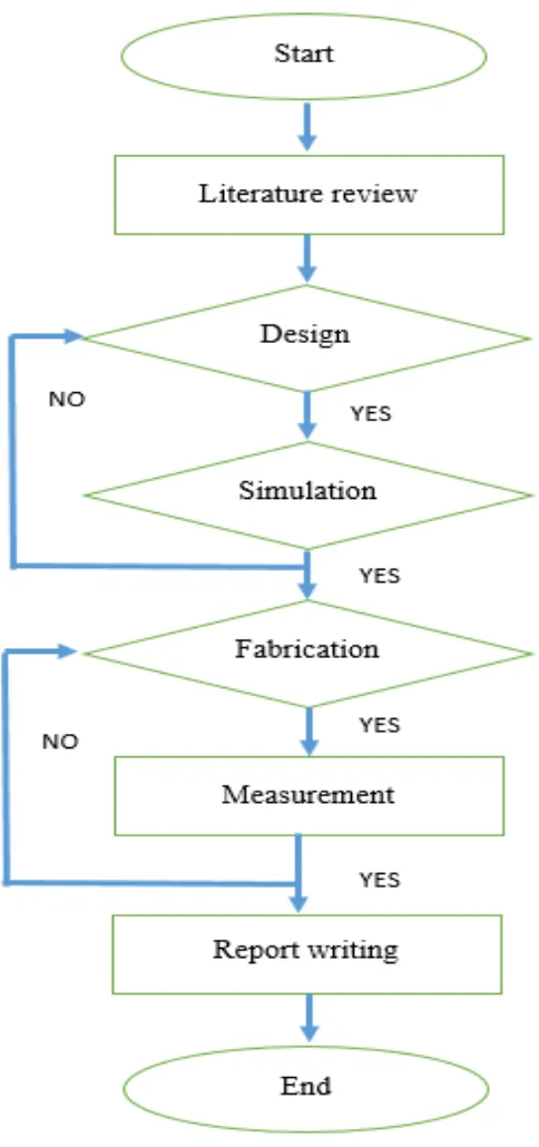
1.2 Flowchart of project 6
2.1 Plane wave and its polarization ellipse at Z=0 15
2.2 Type of polarization 16
2.3 Linear polarization 16
2.4 Circular polarization 17
2.5 Elliptical polarization 18
2.6 Basic Microstrip antenna 20
2.7 Different shapes for microstrip antenna 21
2.8 Coaxial feeding 22
2.9 Direct microstrip feed line 23
2.10 Inset microstrip feed line 24
2.11 Gap-coupled microstrip feed line 24 2.12 Proximity coupled microstrip feeding 25 2.13 Aperture coupled microstrip feed 26 3.1 The flow chart of the project 30 3.2 The options that provided in CST Studio Suite and CST
Microwave Studio been selected 31 3.3 The workspace of the software 32 3.4 The side view of the antenna 32 3.5 The design structure of array antenna for front view 37
3.6 Bottom view for Air gap 38
3.7 Coaxial port for feeding point 39 3.8 The prototype of the array antenna 41 3.9 Antenna and rectifier measurement setup 41
3.10 Vector Network Analyzer 42
xiii
3.12 Connection to measure the power output for antenna 44 3.13 Measurement for output voltage 45 4.1 Bandwidth range for array antenna 48 4.2 Return loss at 2.45 GHz of array antenna 49 4.3 The realized gain of the antenna 49 4.4 The transparent gain with the antenna 50 4.5 Radiation pattern in polar form 50
4.6 The directivity in 3D form 51
4.7 The impedance matching for the antenna 52 4.8 Return loss for measurement of antenna 53 4.9 Comparison between measurement and simulation of
xiv
LIST OF TABLE
TABLE TITLE PAGE
2.1 Summarize of journals for literature study 9 3.1 The design characteristic of the antenna 33 3.2 Design Specifications of Patch Antenna 33
3.3 Antenna dimension 38
3.4 Probe feeding dimension 39
4.1 Result of power transmit and power received 55 4.2 Comparison between simulation and measurement of
1
CHAPTER 1
INTRODUCTION
1.1 Introduction
2
Figure 1.1: RF energy harvesting block diagram
The RF energy system requires the use of antenna as an efficient RF signal power receiving circuit [2]. In the RF signal transmission system generated, amplified, modulated and applied to the antenna. In the meantime, the receive antenna system to collect electromagnetic waves through the antenna and induce alternating Currents is used by the receiver. The antenna capability to transfer energy from the atmosphere to the receiver with the same efficiency as it transfers energy from the transmitter into the atmosphere. The RF signals received by the antenna will be transformed into a DC signal by a diode-based rectifier circuit or a voltage multiplier. This project will represent the design of antenna to use for rectifying circuit based on a concept of RF energy scavenging system. The CST Studio Suite software will be used for the antenna design.
1.2 Objective
3
1.3 Problem Statement
In last few years, there has been a rapid increase in the use of wireless devices in applications such as mobile phones and sensor networks. These devices are powered by a portable device, and limited energy of battery. This means an increase in the use of the application will result in the battery being used has also increased and these batteries need to be replaced often. These batteries contain heavy metals, which if we are not properly disposed of it can leak it contains into the environment pollution increases. Consequently, the use of green technologies such as RF power system is one of the solutions to overcome this problem for developing wireless broadcasting and communications systems generated the free energy.
4
1.4 Scope of Work
5
1.5 Methodology
6
7
1.6 Contribution of Project
At this time, a kind of low-power devices can be operated and charged with use of RF energy is close to us. To use short-distance for a low-power transmitter, an energy scavenging system can be used to trickle charge a number of devices for example GPS or RLTS tracking tags, medical sensor, and consumer electronics devices such as mobile telephones. For long-distance, this system can replace the battery or battery-free sensors known as to control Heating, Ventilation and Air Conditioning also known as HVAC, structural monitoring, and industrial control. Energy scavenging system depends on the power requirements and operations for power can be transmitted continuously, scheduled, or on request. Efforts to eliminate future maintenance to replace the battery can be done using large-scale sensor to reduce labour costs.
8
CHAPTER 2
LITERATURE REVIEW
2.1 Introduction
This chapter discusses some issues that are most important in designing the high gain rectangular patch antenna at 2.45 GHz. This chapter also discussed about basic antenna parameter that will affect the performance of the antenna.
2.2 Critical Literature review
9
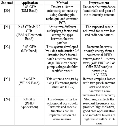
information and facts that can be used in the design process of this project. Table 2.1 summarizes the sample literature review was done.
Table 2.1: Summarize of journals for literature study
Journal Application Method Improvement
[20] (ISM Band) 2.45 GHz microstrip antenna by Design a 10mm using shorting pin technique and common
PCB
Enhance the impedance bandwidth and gain of the microstrip antenna
[21] 2.45 GHz & 5.2 GHz (ISM & Bluetooth
Band)
Adjust two different multiplying factor and
setting the gaps between the two
patches.
The expected result achieved for return loss
and radiation pattern
[22] 2.45 GHz
(ISM band) by using miniaturize 2This system developed nd
iteration koch fractal patch antenna and two
stage Dickson charge pump voltage-doubler
rectifier circuit
Rectenna harvests enough energy from a
commercial RFID
interrogator 3.1 meters away (4W EIRP at 2.45
GHz ISM band) to power up a 1.6 V LED [23] 2.4 GHz
(WLAN Band) This antenna design by using Electromagnetic Band Gap (EBG)
Reduce coupling losses with two patch antenna
layer and wider bandwidth also increases the directivity. [24] 5.8 GHz
(RFID Application)
This design using the orthogonal ports, both
Transmit and receive functions can be implemented on the
same antenna.
Slot length affects the resonant frequency and produce high isolation, good cross-polarization and radiation levels are high waist with 9.3dBi
10
2.3 Antenna Theory
In this antenna theory, basic and understanding of antenna theory is discussed. An antenna is an electrical device which converts electric currents into radio wave or radio wave into electric currents. Antenna usually used with a radio transmitter or radio receiver. In transmission, radio transmitter applies an oscillating radio frequency electric current to the antenna’s terminals and the antennas radiate the energy from the current as electromagnetic waves. Antennas that excite an electrical field are referred to as electrical antennas; antennas exciting a magnetic field are called magnetic antennas. The oscillating electrical or magnetic field generates an electromagnetic wave that propagates with the velocity of light, c. In reception, an antenna intercepts some of the power of electromagnetic waves in order to produce tiny voltage at its terminals. An antenna can be used for both transmitting and receiving.
In other words, an antenna only converts an electromagnetic signal to an electrical signal at receiver or transmitter. If there is 100 percent of efficiency, they radiate no more power than is delivered to their input terminal. This is because all the energy of the signal is absorbed.
2.4 Antenna Properties