Investigation of Mea
Energy harvesting or energy scavenging is conversion process of the ambient energy int energy. In recent years, there has been a growing deployment of wireless sensor networks (WSN) in applications such as in structural monito monitoring, healthcare systems and precision agric
An energy harvesting system consists o subsystems which is receiving antenna and circuitry. An efficient antenna is required to trans power efficiently. The antenna captures the RF sig ambient, and subsequently the rectifier circuit w power from those signals and converts them into D
Microstrip antennas have the attractive fea profile, small size, low cost, and conformability hosts which makes them excellent candidates f this design consideration. [2]. However, micros inherently have certain drawbacks to be given a as narrow bandwidth [3]. Therefore, bandwidth is usually demanded for practical applications. N meet miniaturization requirements of mobile uni size of the antenna is usually required for app mobile communication systems. Thus, size re bandwidth enhancement are major design consi practical applications of microstrip antennas [4].
n of Meander Slots To Microstri
Patch Antenna
. Zakaria2, M. Z. A. Abd Aziz, M. N. Husain, M. A. Mutali
arch and Innovation (CeTRI), Faculty of Electronic and Comput elaka (UTeM), Hang Tuah Jaya 76100, Durian Tunggal, Melak
[email protected], [email protected] to transfer wireless RF signals from the gn considerations for
].
The meander line antenna is one antennas. Meander line technology antenna with a small size and provides [5]. Having the advantage to miniatu proposed methods [6] [7] [8], slotted m chosen because it is able to reduce the s smaller and very flexible to be shifte The performance of the slotted meande on various factors such as the position number of turns of the meander line. Thi of meander slot existed in particular ant
II. ANTENNA DESI
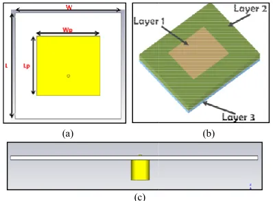
The geometry for the slotted meande of 3 layers [11] which are patch (Layer (Layer 2) and ground plane (Layer 3) a antenna was simulated on an FR4 sub constant of 4.4 and a thickness of 1.6 and the bottom layer of the patch material from the copper annealed w mm. The ground also consists of SM used as an RF connector to connect the the 50 Ω microstrip lines on a boar chosen as the feed because it can be pla the impedance match will depend on it [12]. The geometry of the microstrip in Fig. 1. The basis of the antenna struc rectangular patch element with the dim and length Lp.
(a)
(c) Figure 1: Structure of microstrip antenna; (
view (c) side vie iniaturize antenna like other otted meander line antenna is e the size of the antenna. It is shifted or relocated [9][10]. eander line antenna depends osition of meander slots and ine. This includes the number lar antenna.
ESIGN
meander line antenna consists (Layer 1), dielectric substrate er 3) as shown in Fig. 1. The R4 substrate with dielectric of 1.6 mm. While the upper n be placed at any location and on its location on the patch rostrip patch antenna is shown nna structure is chosen to be a the dimensions of width Wp
(b)
Patch length and width are calculated b transmission line model.
Formula for patch width [13][14] is given by
W
And length is given by;
L 2∆L
The parametric study method is used to ob dimension of microstrip patch antenna to ach operation.
Fig. 2 below shows the parameters of the mea will be used in all designs of slotted meander l Basically it consists of the width of horizonta length of horizontal line LH, width of vertical lin of vertical line LV and the number of turns, N.
Figure 2: Design parameter of slotted meander line a
For all designed structure, the width of the hori WH is fixed to 1mm. The antennas are categori the number of slots attached to the microstrip ante
Fig. 3 shows the slotted meander line antenna Two meander slots each are located at the right, l the probe feed.
ted by using the
(1)
(2)
to obtain the best o achieve 2.4GHz
he meander slot that nder line antennas. izontal length WH, cal line WV, length
r line antenna
f the horizontal line, tegorized based on ip antenna.
ntenna with 6 slots. right, left and top of
Figure 3: Structure of 6 meande
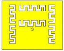
Fig. 4 shows the slotted meander lin All of the meandered slots have the sa 2. Four of them are located at the corne remaining 3 meander line slots are loca left of the probe feed.
Figure 4: Structure of 7 meand
III. EXPERIMENTAL RESULTS
Fig. 5 shows the simulation result return loss and bandwidth of the recta antenna.
Figure 5: Simulated and measured return loss o patch antenna
The simulation return loss at 2.4 which meets the requirement of the des 10 dB (90% of power fed is absorbed). of simulation and measurement r microstrip patch antenna.
meander slot antenna
der line antenna with 7 slots. he same number of turns, N = corners of the antenna while re located at the top, right and
meander slot antenna
LTS AND ANALYSIS
result of frequency response, rectangular microstrip patch
loss of the rectangular microstrip
TABLE I. SIMULATION AND MEASUREMENT RESULT OF RECTANGULAR MICROSTRIP PATCH ANTENNA
) + ( 1 .
Sim 2.4 GHz J14.33 dB 42.68 MHz 4.23 dB
Mea 2.46 GHz J17.05 dB 48.08 MHz 2.67 dB
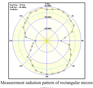
The simulation bandwidth produced is satisfactory and sufficient to cover the 2.4 GHz span of RFID applications. This 10 dB bandwidth ranges from 2.4424 GHz to 2.4905 GHz which is practically adequate. The measurement result shows that the resonant frequency shifted to the left to 2.46 GHz displaying return loss of J17.05 dB which is better than the simulation return loss. The radiation pattern of this antenna is shown in Fig. 6 and Fig. 7.
(a) (b)
Figure 6: Simulated radiation pattern of rectangular microstrip patch antenna
at (a) HJfield (b) EJfield.
Figure 7: Measurement radiation pattern of rectangular microstrip patch antenna
From the return loss graph shown in Fig. 8 below, the 6 meander slot antenna has a good return loss with J16.52 dB. The additional number of slotted meander lines on the antenna improved the return loss and also the bandwidth.
Figure 8: Simulated and measured return loss of 6 meander slot antenna
The measurement result shows that this antenna only able to get a slightly lower than J10 dB return loss. It managed to achieve J11.52 dB. The antenna obtained a higher gain compared to 7 meander slot antenna. Table 2 shows the comparison of simulation and measurement result for 6 meander slot antenna.
TABLE II. SIMULATION AND MEASUREMENT RESULT OF 6MEANDER SLOTS ANTENNA
) + # ( 1 .
Sim 2.41 GHz J16.52 dB 43.01 MHz 3.65 dB
Mea 2.32 GHz J11.52 dB 28.27 MHz 1.69 dB
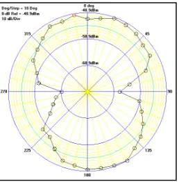
The simulated radiation pattern is as presented in Fig. 9 below. The simulated HPBW for EJfield is 120.7º at 2.4 GHz while the HPBW for HJfield is 98.9º at 2.4 GHz. The measured radiation pattern is shown in Fig. 10.
(a) (b)
Figure 10: Measured radiation pattern of 6 slot meander line antenna
From the return loss graph shown in Fig. 11 below, the 7 meander slot antenna achieved a return loss of J19.42 dB. The position of the slotted meander lines at the corners of the antenna improved the return loss as well as the bandwidth.
For measured results, this antenna is only able to get a slightly lower than J10 dB return loss. It managed to achieve J 14.35 dB of return loss. One of the disadvantages of this antenna is its low gain compared to 6 meandered slot antenna.
Figure 11: Simulated and measured return loss of 7 meander slot antenna
Table 3 shows the comparison of simulation and measurement result for 7 meandered slot antenna.
TABLE III. SIMULATION AND MEASUREMENT RESULT OF 7MEANDER SLOTS ANTENNA
) + ( 1 .
Sim 2.40 GHz J19.42 dB 32.08 MHz J0.76 dB
Mea 2.41 GHz J14.35 dB 33.27 MHz J1.28 dB
The simulated radiation pattern is as presented in Fig. 12. The simulated HPBW for EJfield is 123.8º at 2.4 GHz while the HPBW for HJfield is 94.4º at 2.4 GHz. As for measurement radiation pattern, it is shown in Fig. 13.
(a) (b)
Figure 12: Simulated radiation pattern of 7 meander slot antenna at (a) HJfield (b) EJfield
Figure 13: Measured radiation pattern of 7 meander slot antenna
A comparison of return loss has been made between simulation and measurement. For this purpose, the data obtained from the measurement process has been exported into the CST Microwave software in order to get a better picture of the comparison.
As for the measured radiation pattern, antenna with 7 meandered slots shows an omnidirectional radiation pattern rather than the bidirectional pattern in simulation.
The comparison of simulation and measurement results for both antennas has been converted into table form for a better picture. Table 5 below shows the detailed comparison.
TABLE IV. RESULT COMPARISON OF 6MEANDER SLOTS AND 7MEANDER SLOTS ANTENNA
2 * 0 *
* *
) + ./$
2.41 2.32 2.40 2.42
( ./$
1
J14.54 J11.52 J19.42 J14.35
1 /$
43.0 10.3 32.1 52.3
The gain of 7 meander slot antenna is negative which means that the antenna gain at particular direction is less than the isotropic antenna. It happened due to the mismatch loss where the antenna has a low efficiency. The meander slot position also is one of the factors that affect the antenna gain. Meanwhile, the measured gain is also negative in accordance with the simulation result and due to the losses influenced by the distance, cables and connectors.
IV. CONCLUSION
In this paper, the effect of meander slots on a microstrip patch antenna is investigated. Two slotted meander line antennas with different number of slots has been designed, simulated and fabricated. 7 meander slot antenna obtained better performance than the 6 meander slot antenna in terms of return loss, bandwidth and resonant frequency. However, 6 meander slot antenna has a better simulated and measured gain. Further works can be done to explore the designed antenna for RF energy harvesting applications.
ACKNOWLEDGMENT
The authors would like to thank Universiti Teknikal Malaysia Melaka (UTeM) for sponsoring this work under the CoE, short terms grant UTeM, PJP/2012/CeTRI/Y00001.
REFERENCES
[1] Z. Zakaria, N. A. Zainuddin, M. N. Husain, M. Z. A. Abd Aziz, M. A. Mutalib, A. R. Othman "Current Developments of RF Energy Harvesting System for Wireless Sensor Networks ", AISS: Advances in Information Sciences and Service Sciences, Vol. 5, No. 11, pp. 328 J 338, 2013.
[2] M. A. S. Alkanhal, “Composite compact tripleJband microstrip antennas,” Progress In Electromagnetics Research, PIER 93, pp. 221J 236, 2009.
[3] A. A. Lotfl Neyestanak, “Ultra wideband rose leaf microstrip patch antenna,” Progress In Electromagnetics Research, PIER 86, pp. 155J168, 2008.
[4] K. L. Wong, “Planar antennas for wireless communications”, WileyJ Interscience, 1st edition, New York, 2003.
[5] A. Khalegi A. Azooulay. J. C. Bolomey, "A Dual Band Back Couple Meandering Antenna For Wireless LAN Applications", Gof Survvette, France, 2005.
[6] G. T. Jeong, W. S. Kim, K. S. Kwak, Design of a cornerJtruncated squareJspiral microstrip patch antenna in the 5JGHz band, Microwave and Optical Technology Letters, Volume 48, Issue 3, pp: 529J532 [7] L. C. Godara, Handbook of Antennas in Wireless Communication. Boca
Raton, FL: CRC Press, 2002.
[8] D. Misman, M. Z. A. Abd Aziz, M. N. Husain, M. K. A. Rahim, P. J. Soh, “Design of Dual Beam Meander Line Antenna”, Proceedings of the 5th
European Conference on Antennas and Propagation (EUCAP), pp. 576J578, April 2012.
[9] L. C. Godara, Handbook of Antennas in Wireless Communication. Boca Raton, FL: CRC Press, 2002.
[10] M. Z. A. Abd Aziz, Z. Zakaria, M. N. Husain, N. A. Zainuddin, M. A. Othman, B. H. Ahmad, "Investigation of Dual and Triple Meander Slot to Microstrip Patch Antenna," Microwave Techniques (COMITE), pp. 36J39, 17J18 April 2013.
[11] I. J. Bahl, P. Bhartia, “Microstrip Antennas”, Artech House, 1980.Newble D., and Cannon R., A Handbook for Teachers in Universities and Colleges, Kogan Page, 1991.
[12] S. Haider, Microstrip Patch Antennas for Broadband Indoor Wireless Systems. M. Sc. Thesis. The University of Auckland: New Zealand, 2003.
[13] C. T. P. Song, P. S. Hall, H. GhafouriJShiraz, D. Wake, “Triple Band Planar Inverted F Antennas for Handheld Devices”, Electron Letter 36, pp. 112J114, 2000.