DOI: 10.12928/TELKOMNIKA.v14i4.4019 1356
Least Mean Error Algorithm for Determining the
Radome Dimension of Planar Antenna
Adya Pramudita*1, Yuyu Wahyu2
1
Telecommunication Research Group, Electrical Engineering Department Atma Jaya University, Jl. Sudirman 51, Jakarta, 021-5708826.
2
Pusat Penelitian Elektronika dan Telekomunikasi, Lembaga Ilmu Pengetahuan Indonesia Jl. Sangkuriang-Komplek LIPI, Bandung, 022-2504660
*Correspending author, e-mail: [email protected]
Abstract
Antennas are generally contructed from metallic materials; therefore it is prone to corrosion when installed outdoors. Radome is an important part of an outdoor antenna that serves to protect the antenna from environmental conditions. Radome structure is not expected to have a significant influence on the characteristics of the antenna. Parametric study is generaly applied in finding the optimum antenna dimenssion included radome. A method for guiding a parametric study proses in finding the optimum antenna dimensions has investigated and proposed in this paper. In this study, a method for determining the optimum radome dimension for planar antenna by applying the algorithm Least Mean Error (LME) has investigated. LME algorithm is used to find the optimum dimensions of the radome. The simulation results show that the proposed method can be applied to determine the dimensions of a planar antenna.
Keywords: radome, dimension, planar, antenna
Copyright © 2016 Universitas Ahmad Dahlan. All rights reserved.
1. Introduction
Antennas are generally composed of metallic materials that need to be protected against corrosion process when the antenna is operated as an outdoor antenna [1-3]. The addition of radome structure is not expected to have a significant influence on the characteristics of the antenna, therefore its need to be taken into consideration at the antenna design. Radome is also expected to have a simple structure and provide minimum final dimensions of the antenna. For the planar antenna, the simplest radome structure is the cubical structure. On most surfaces of cubical structure, radome antenna position is parallel to the antenna surface and futher more the wave propagation model in layered medium is potentialy be used as a theoretical approach. Several techniques for analyzing radome that have been studied include a combination of several numerical methods with complex computing [4-6].
Parametric studies often used in designing the antenna in order to determine the best dimensions of the antenna [7, 8]. Problem that addressed in this paper is determined due to the fact that determining the antenna's optimum dimenssion by performing several parametric studies may time consuming and need a larger computation resources. To improve the effectiveness of design process in determining the best dimensions of the antenna, a searching algorithm is studied and proposed to be applied in the parametric study. In the previous research, a deterministic approach was proposed for optimal synthesis of linear phase reconfigurable isotropic sparse array. The optimization step of synthesis procedure is based on minimum square error between reference and actual radiation pattern [9]. Least Mean Error (LME) algorithm is searching algorithm that frequently used and has simple computation. In this research, implementation of LME algorithm in determining the radome dimensions of a planar antenna has investigated. In this research, a method of determining dimensions of planar antenna radome has investigated by using a case study on a triangular-shaped planar monopole antenna which is studied in the previous research as an antenna for digital TV broadcast system [10].
of the LMS algorithm. Chapter III contains the results and discussion of the results that have been obtained and in chapter IV is the conclusion.
2. Research Method
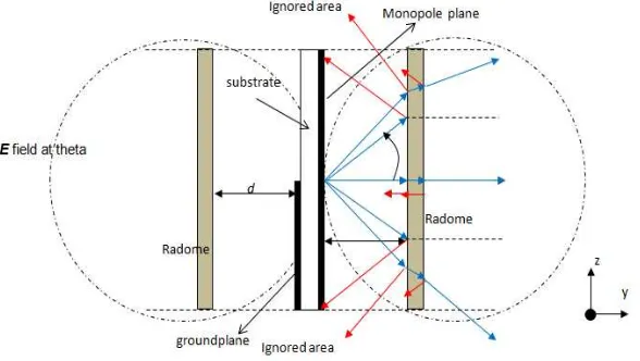
[image:2.595.145.439.233.399.2]Radome is a structure used to protect parts of the antenna that serves as a radiator to the effects of environmental conditions [1-3]. Radome structure is generally composed by a dielectric material and materials that are often used to manufacture the antenna radome include Polyester, Epoxy, cyanate ester, polyimide, PTFE, polycarbonate, fiberglass [11]. In a certain application such as rocket and radar, the selection of radome materials must also considered environmental conditions that are more extreme [4].
Figure 1. Modelling of the radome effect to the planar antenna
Radome structures and its materials potentially affect to the characteristics of the antenna such as radiation pattern and the input impedance of the antenna [5, 6] so the process of designing the shape of the radome and choosing the radome materials need to consider its effect on the antenna characteristics. Radome influence on the electromagnetic waves radiated by an antenna is investigated by using the model that illustrated in Figure 1. In this case, when the most of radome surface are in parallel position with antenna surface then the effect on the radiation patern is significant in perpendicular direction. Therefore, the model is derived only in the point of view antenna input impedance. In z direction of the planar antenna, radome effect is assumed less significant because E field radiated by the antenna has small value and the radome area which is perpendicular to its direction has small dimension.
If the E field that radiated by the planar antenna in the plane zy plane is approximated by the E field of half wave length dipole antenna (1) as illustrated in Figure 1 that the field E of the antenna is partly reflected back by the surface of the radome to the antenna and affected to the antenna characteristics. When the radome has electrical properties
rand
r electromagnetic wave that radiated by the antenna will be partially reflected back by the reflection coefficient that can be calculated based on (2) withZ
a is the air intrinsic impedance (
120
) andZ
r is the intrinsic impedance that can be determined by (3).
sin
)
cos
5
.
0
cos(
)
(
E
(1)a r
a r
Z
Z
Z
Z
r r r
Z
0 0
(3)The comparison between E field that transmitted by the antenna (
E
i) and E field thatreflected back to the antenna (
E
r2) is determined by (4).
5 . 0 0 0 2 ) 5 . 0 ( 2 ) 5 . 0 ( ) ( 2 d E d E E E x i rr (4)
The reflection coefficient of the antenna is also influenced by the electromagnetic wave that reflected back by the radome surface and finally, when
nr is the reflection coefficient ofthe antenna without radome and
ris the reflection coefficient of the antenna with radome, then the total reflection coefficient of the radome can be calculated using (5-6).r nr i r r i r r i r nr
E
E
E
E
E
E
E
1 2total 2 1
,
,
(5)0 0
)
(
)
(
)
(
Z
f
Z
Z
f
Z
f
in in nr
(6)Calculation of the antenna input impedance is approached by biconical antenna theory that is explained first by Schelkunoff [12]. According to the image theory, the ground plane will generate the image of the upper cone and the electrical dimension of the antenna is the same with biconical. Input impedance of single cone above ground plane is half of the biconical antenna input impedance. Furthermore the input impedance of monopole calculated as (7-10) that also mentioned in [10].
inB
in
f
Z
Z
(
)
0
.
5
(7)
L
f
f
jZ
Z
L
f
jZ
f
Z
Z
f
Z
L k k L k inB)
(
tan
)
(
)
(
tan
)
(
)
(
(8)L
f
f
jZ
Z
L
f
jZ
f
Z
Z
f
Z
m k k m k L)
(
tan
)
(
)
(
tan
)
(
)
(
(9)L
f
f
jZ
Z
L
f
jZ
f
Z
Z
f
Z
m k k m k L)
(
tan
)
(
)
(
tan
)
(
)
(
(10)With
is2
/
is, L is the length of the conical and Zk is the characteristic impedance of thetransmission line models of biconical antenna that can be determined by (11).
)
2
ln(cot
c kZ
Effect of the environment around the antenna, aspecially at near field radius need to be considered in the installation or antenna measurement [12]. The radome effect will be increased when the radome position is closer to the antenna and vice versa. In designing the antenna radome, minimun distance of the radome to the antenna surface (d) is also an important consideration in addition to its effect on the antenna characteristics.
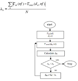
The radome effect can be obseved by calculating the total of reflection coefficient in (5). In this paper, Least Mean Error (LME) algorithm is applied to find the minimum distance of the radome. The minimum average difference (∆r) between
nrand
totalbecomes stoppingcreterial of the algorithm calculation. LME flow chart is shown in Figure 3. The value of ∆r
describes the satisfication level that should be reached by the algorithm that related with the minimum distance between radome and antenna. Calculation was done over N samples in the frequency range of observation. ∆n is the average difference (∆r) between
nrand
total at n-thiteration. When the ∆n still larger than ∆r, then d for next iteration is added by ∆s. ∆s is step size
for updating the value of d in each iteration that is determined base on the minimum resolution of radome fabrication. In this research we used 0.5 mm for ∆s.
N
nf
d
nf
n
n total nr
n
)
,
(
)
(
[image:4.595.122.373.279.539.2](12)
Figure 2. Flow chart of LME algoritm which is used to find the minimum value of d
3. Results and Analysis
Figure 3. The effect of d to the antenna reflection coefficient
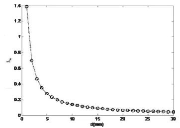
Figure 4. Average difference (∆n) between
nr
and
total in corresponding with radome distance dContrast dielectric between radome material and air between radome and antenna surface also affects to the amount reflection wave. Based on the information about antenna radiation patern, reflection coefficient model of planar antenna due to the existence of radome can be derived. The main purpose of studying the influence of radome on antenna input impedance is determining the minimum dimension of the radome on antenna design. Radome minimum distance is the value of d which causes the average difference between
nrand
total is 0.1 dB or other value that related to the satisfaction level in designing the antenna. The radome minimum distance can be determined by running the LSE algorithm that illustrated as flow chart in Figure 3 with step size 0.5 mm. The result shows that the radome minimum distance is 13.5 mm and reflection coefficient comparison between antenna without radome and antenna with radome at a distance of 13.5 mm is shown in Figure 5. At a distance 13.5 mm, radome effect to the antenna input impedance has been small enough. Figure 5 shows that reflection coefficient of the antenna has very small discrepancy comparing with without radome. Results in Figure 5 indicated that the proposed method can be used to determine the minimum dimensions of the radome for planar antenna. the proposed method is helpful to accelerate the process of parametric studies that are often conducted on the antenna design process.Figure 5. Reflection coeficient comparison between antenna without radome and antenna with radome at a distance of 13.5 mm
4. Conclusion
[image:5.595.191.402.513.657.2]due to the existence of radome has derived base on the antenna radiation patern. The results showed that the method is very helpful to accelerate the process of parametric studies that are generally necessary for determining the optimum dimensions of the antenna. The study was conducted refers to a single parameter, namely antenna input impedance. Further studies also need to be done with reference to the other antenna parameters.
References
[1] Hongfu Meng, Wenbin Dou. Analysis and Design of Radome in Millimeter Wave Band. In: Igor Minin. Editors. Microwave and Millimeter Wave Technologies: from Photonic Bandgap Devices to Antena
and Applications.InTech. 2010: 383-403.
[2] Persson K, M Gustafsson, G Kristensson. Reconstruction and visualization of equivalent currents on a radome using an integral representation formulation. Progress in Electromagnetics Research B. 2008; 20: 65-90.
[3] Sukharevsky OI, VA Vasilets. Scattering of reflector antena with conic dielectric radome. Progress In Electromagnetics Research B. 2008; 4: 159-169.
[4] F Chen, Q Shen, L Zhang. Electromagnetic Optimal Design and Preparation of Broadband Cearmic Radome Material with Graded Porous Structure. Progress In Electromagnetics Research. 2010; 105: 445-461.
[5] HF Meng, WB Dou. A Hybrid Method for the Analysis of Radome Enclosed Horn Antena. Progress in
Electromagnetics Research. 2009; 90: 219-233.
[6] R Orta, F Tascone, Z Rodolfo. Performance Degradation of Dielectric Radome Covered Antenas.
IEEE Transactions on Antenna and Propagation. 1998; 36(12): 1707-1713.
[7] Ahmed Boutejdar, Ahmed A Ibrahim, Edmund Burte. A Compact Multiple Band-Notched Planer Antenna with Enhanced Bandwidth Using Parasitic Strip Lumped Capacitors and DGS-Technique. TELKOMNIKA Indonesian Journal of Electrical Engineering. 2015; 13(2): 203-208.
[8] Quazi Delwar Hossain, M Azad Hossain, Muhammad Asad Rahman. Dual Orthogonal Feed Circular Polarization Array Antenna Using Microstrip Slot Feed Network. International Journal of Electrical and Computer Engineering (IJECE). 2015; 5(5): 1119-1127.
[9] AF Morabito, T Isernia, L Di Donito. Optimal Synthesis of Phase-Only Reconfigurable Linear-Sparse
Arrays having Uniform-Amplitude Exitations. Progress in Electromagnetics Research. 2012; 124:
405-423.
[10] AA Pramudita. A Method for Determining the Dimension of Planar Monopole Triagular Antenna.
Proceedings of IEEE International Conference of Aerospace Electronic and Remote Sensing. 2014: 63-66.
[11] Cobham. Dielectric Constant, Loss Tangent and Teperature Range of Typical Radome material. 2016.