e-ISSN: 2278-2834,p- ISSN: 2278-8735.Volume 5, Issue 3 (Mar. - Apr. 2013), PP 65-69 www.iosrjournals.org
Design of Low Noise Amplifier for Radio over Fiber at 5.2 GHz
A.
Salleh
1, M. Z. A Abd Aziz
1, N. R. Mohamad
1, M. A. Othman
1, Z.
Zakaria
1, M. H. Misran
11
(Center for Telecommunication Research & Innovation (CeTRI), Faculty of Electronic & Computer Engineering, Universiti Teknikal Malaysia Melaka (UTeM), Malaysia)
Abstract : This paper presents the design and simulation of low noise amplifier (LNA) used in an active radio access point (RAP) for Radio over Fiber (RoF) technology at 5.2 GHz. RoF is integration of optical fiber for radio signal transmission within network infrastructures that is considered to be cost effective, practical and relative system configuration for long haul transport of millimeter frequency band wireless signal. The LNA designed function is to amplify extremely low signals without adding noise, thus preserving the required Signal Noise Ratio (SNR) of system at extremely low power signal. The implementation of design is based on Agilent ATF-5143 transistor and Microwave Office software is used to perform the simulation in S-parameters. The design and simulation process including selecting the transistor based on RoF requirements, stability of transistor, matching network, biasing and optimization. The design has shown an acceptable behavior with gain of 16.046 dB and noise figure of 0.9368 dB using conjugate matching method.
Keywords -LNA, RoF, RAP, Conjugate Matching Method, S-parameters
I. INTRODUCTION
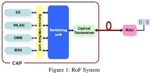
Radio over Fiber (RoF) is well established technology that used intensively worldwide for delivering radio signal from a Central Station (CS) to RAPs via an optical fiber [1]. In new concept of wireless architecture using this technology, all the signal processing associated with the base station, usually found in the RAP or remote antenna unit (RAU), can now be moved to the CS. With such advantages of optical fiber as low loss, large bandwidth and transparent characteristics, RoFs system can simultaneously support multi-standard applications including cellular services and wireless local area networks (WLANs) [2]. 5.2 GHz frequency is one most commonly used license free frequencies which based on IEEE802.11 standard for WLAN. RoF systems are expected to play an important role in future wireless communication and phased array antenna sensor systems [3-6]. Fig. 1 describes the basic diagram of RoF system [7].
Figure 1: RoF System
The only components required at the passive RAP are Electro Absorption Modulator (EAM) and antenna where EAM is used as a remote transceiver. There are practical limitations on the power that can produce by the passive RAP which can affect the dynamic range. The operating range limitations of the passive picocell optical RAP in RoF system can be overcome by using amplification within the antenna unit. Picocell has coverage range up to 100 m. To achieve this distance, RAP needs to operate in active mode, by inserting RF amplifier between optoelectronics modulator and antenna for downlink path and inserting LNA between antenna and optoelectronic modulator for uplink path. The LNA is possible to improve the receiver sensitivity and to also increase the depth of the modulation that optoelectronics modulator produces on the uplink signal [1].
applications where the cost is an important consideration. Likely the LNA of general RF system, amplifier design for RoF involves many tradeoffs between noise figure, gain, linearity, impedance and matching [8].
Central
Station EAM
BPF
LNA
PA
BPF
Downlink
Uplink
C
Radio Access Point
Figure 2: Active optical radio access point
Generally, the main goal of the LNA is to decrease of the incoming noise and amplifying a desired signal within a certain frequency range to increase the signal to noise ratio (SNR) of communication system and improve the quality of received signal as well. Noise in optical receiver (RAP) can be divided into three categories: the noise contributed by optical sources or optical transmission path, the noise arising from photo-generated carriers of carriers transport over the p-n junction and the Johnson noise from the amplifier. Only the third noise can be optimized by a proper circuit design [8]. Therefore the suitable circuit topology and noise optimal technologies are selected to satisfy these goals.
In this paper, a 5.2 GHz LNA is designed in active RAP for RoF technology based on conjugate matching method using Microwave Office software. The maximum gain or conjugate matching method is in the single stage amplifier design. This method will be realized when the overall gain given by transistor, G0 provide a conjugate match between the amplifier source or load impedance and the transistor. The performance of LNA is depending on S-parameters which used to determine the stability, noise figure, maximum gain and matching network and DC biasing.
II. DESIGN METHODOLOGY
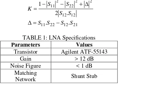
The design methodology of LNA including LNA specifications, stability, matching network and DC biasing. LNA specifications including transistor type, matching network method, gain and noise figure is shown in Table 1. A critical step in any LNA design is the selection of transistor which ATF-55143 transistor from Agilent is used. The ATF-55143 is one of a family of new high dynamic range, low noise enhancement mode pHEMT devices designed for use in low cost commercial applications in the Very High Frequency (VHF) band through 6 GHz. Low cost Field Effect Transistor (FET) are often used due to their low noise figures, high gain and high linearity.
When embarking on any amplifier design it is very important to spend time checking on the stability of the device chosen, otherwise the amplifier may well turn into an oscillator. The main way of determining the stability of a device is to calculate the Rollett’s stability factor (K) based on set of S-parameters for the device at the frequency of operation [9]. S-parameters of transistor usually can be found from data sheet of transistor or through simulation using Microwave Office software. The stability criteria can be written as [9].
12 12 2 2 22 2 11
. 2 1
S S
S S
K (1)
S11.S22S12.S21 (2)
TABLE 1: LNA Specifications
Parameters Values
Transistor Agilent ATF-55143
Gain > 12 dB
Noise Figure < 1 dB
Matching
Network Shunt Stub
determined, and the stable regions for reflection coefficient for source and load (ΓS and ΓL) have been located on the Smith chart, the input and output matching section can be designed.
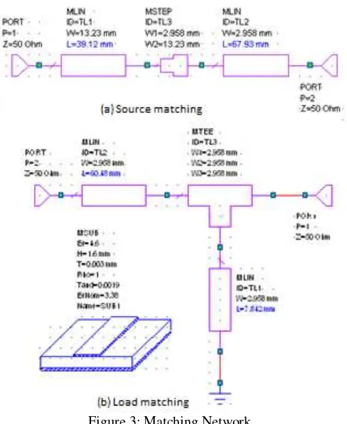
The matching network is important because maximum power will delivered when the load is matched to the line. There are several types of practical matching network such as matching with lumped elements, single stub tuning and quarter wave transformer. The important factors in the selection of a particular matching network include complexity, bandwidth, implementation and adjustability. For this design, the input is matching using the quarter wave transformer while the output is matched using shunt short stub. . Fig. 3 shows the source matching and load matching.
Figure 3: Matching Network
DC biasing of the ATF-55143 is accomplished by the use of a voltage divider consisting of R1 and R2. The voltage for the divider is derived from the drain voltage which provides a form of voltage feedback through the use of R3 to help keep drain current constant. Resistor, R5 (approximately 10 kΩ) is added to limit the gate current of enhancement mode devices such as the ATF-55143. This is especially important when the device is driven to P1dB. Capacitors C2 and C5 provide a low impedance in-band RF bypass for the matching networks. Resistors R3 and R4 provide a very important low frequency termination for the device. Capacitors C3 and C6 provide the low frequency RF bypass for resistors R3 and R4. Fig. 4 shows the DC biasing of LNA. Resistor R3 is calculated based on desired VDS, IDS and available power supply voltage. The values of R1 and R2 are calculated based on the following formula.
BB GS
I V
R1 (3)
GS DS DS
V R V V
R2 1 (4)
DS BB DS DD
I I
V V R
3 (5)
Where,
VDD is the power supply voltage. VDS is the device drain to source voltage. IDS is the desired drain current.
Figure 4: DC Biasing
III. RESULTS AND ANALYSIS
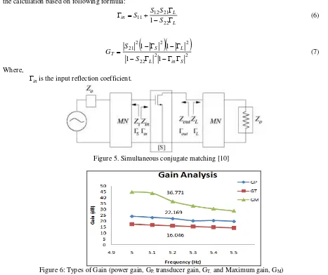
Simulation maximum gain or conjugate matching method will be realized when matching sections provide a conjugate match between the amplifier source or load impedance and the transistor. Fig. 5 shows the simultaneous conjugate matching which provide the maximum power transducer gain (GT). GT is the ratio of power delivered to the load to the power available from the source. From the simulations, three types of gain are considered as shown in Fig. 6. The concern in the design is GT = 16.046 dB which shows the overall gain of LNA including gain from transistor, Go and input and output matching. All the simulation results are proved by the calculation based on following formula:
is the input reflection coefficient.
Figure 5. Simultaneous conjugate matching [10]
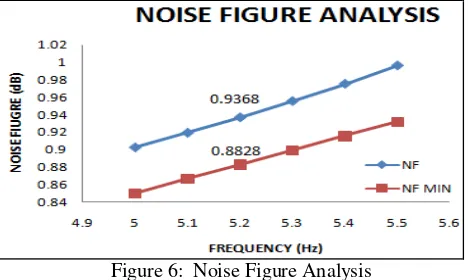
The noise figure, NF of LNA is defined as the ratio of the total available noise power at the output of the amplifier to the available noise power at the output that would result only from the thermal noise in the source resistance. Thus NF is a measure of the excess noise added by the amplifier. The noise figure of an amplifier generally varies as:
2 min s opt
s n
Y Y G R F
NF (8)
WhereYsis the source admittance,Yopt is the optimum source admittance, Fminis the minimum noise figure,Rn
is the equivalent noise resistance and Gsis the real part of Ys. From (3), the NF = 1.0239 dB but the results from the simulation is better as shown in Fig. 6, NF = 0.9368 dB.
Figure 6: Noise Figure Analysis
The LNA designed act as to boost the desired signal power while adding as little noise and distortion as possible so that the retrieval of this signal is possible in the later stages in the system. For any two-port network, the noise figure measures the amount of noise added to a signal transmitted through the network. As used here, stability measures the tendency of an LNA to oscillate. Maximum available gain is a figure of merit for the LNA, which indicates the maximum theoretical power gain when it is conjugate matched to its source and load impedances.
IV. CONCLUSION
In this paper proposed designing and analysis low noise amplifier (LNA) in the RAP at 5.2 GHz for RoF technology. In order to achieve that, the simulation model for the transistor, given from free scale, has been used in the designing process. The achieved results given by simulations (gain of 16.046 dB and noise figure of 0.9368 dB) are meets the requirement for RoF technology. So an interesting future work would be to improve the performance of the LNA by compare the results between fabrication process and simulations and achieve a higher gain and lowest noise figure.
Acknowledgements
The author would like to thank Universiti Teknikal Malaysia Melaka (UTeM) for the grant number PJP/2011/FKEKK (35C)/S00933.
REFERENCES
[1] P. P Smyth, “Optical Radio – A review of a Radical New Technology For Wireless Access Infrastructure,” In: Peter Smyth. Mobile and Wireless Communication: Key Technologies and Future Applications. London. : The Institution of Electrical Engineers, 2004. [2] Hyo-Soon Kang, Myung-Jae Lee and Woo-Young Choi, “Multi Standard Radio over Fiber Systems using CMOS-Compatible Si
Avalanche Photodetector,” Asia Pacific Microwave Photonics Conference, pp. 302–35, 2008.
[3] Hamed Al-Raweshidy, Shozo Komaki, "Radio over Fiber Technologies for Mobile Communications Networks,". Artech House, Boston, 2002.
[4] P.K.Tang, L.C.Ong, B.Luo,A.Alphones and M.Fujise, "Transmission of Multiple Wireless Standards over a Radio-over-Fiber Network,", 2004.
[5] Sangil Kim, Hodeok Jang et al,"Performance Evaluation for UWB Signal Transmission with Different Modulation Schemes in Multi-Cell Enviroment Distributed Using ROF Technology,", 2004.
[6] Gurprakash Singh and Arokiaswami Alphones, "OFDM Modulation Study for Radio-over-Fiber System for Wireless LAN (IEEE802.11a)," 4th International Conference on Information, Communications & Signal Processing , 2003.
[7] Razali Ngah, Teguh Prakoso & Tharek Abdul Rahman, “Coverage Range and Cost Comparison of Remote Antenna Unit Designs for
In building Radio over Fiber Technology,” ITB J. ICT Vol. 2, No. 1, 2008.
[8] Pengcheng Xiou, Zhigong Wang, “5.2GHz CMOS Narrow Optical Receiver for Radio over Fiber,” Proc. of International Conference on Communications, Circuits and Systems, pp. 1937-1941, 2006.
[9] D. M. Pozar, “Microwave and RF Design of Wireless Systems”, John Wiley & Sons, Inc., 2001.
[10] G. Gonzalez, “Microwave Transistor Amplifiers:Analysis and Designs”, 2nd