RENEWABLE ENERGY (SOLAR POWER) MINI PROTOTYPE PLANT WITH SCADA SYSTEM
Muhammad Nashriq bin Mohd Haris
“ I hereby declare that I have read through this report entitle “Renewable Energy (Solar Power) Mini Prototype Plant with SCADA System” and found that it has comply the partial fulfillment for awarding the degree of Bachelor of Electrical Engineering (Industrial Power)”
Signature : ...
Supervisor’s Name : MR. MASLAN BIN ZAINON
RENEWABLE ENERGY (SOLAR POWER) MINI PROTOTYPE PLANT WITH SCADA SYSTEM
MUHAMMAD NASHRIQ BIN MOHD HARIS
A report submitted in partial fulfillment of the requirements for the degree of Electrical Engineering (Industrial Power)
Faculty of Electrical Engineering
UNIVERSITI TEKNIKAL MALAYSIA MELAKA
I declare that this report entitle “Renewable Energy (Solar Power) Mini Prototype Plant with SCADA System” is the result of my own research except as cited in the references. The report has not been accepted for any degree and is not concurrently submitted in candidature of any other degree.
Signature : ...
Name : MUHAMMAD NASHRIQ BIN MOHD HARIS
ACKNOWLEDGEMENT
First and foremost, I would like to express my thankfulness and gratitude to Allah S.W.T who has given me inspiration and strength for me to complete this progress report.
Besides, I wish to express my sincere appreciation to my supervisor, Mr. Maslan bin Zainon, for give me a lot of encouragement, guidance critics and support to accomplish this progress report. I also would like to show my appreciation to all my lectures and technical staffs that have taught me with strong theories especially in electrical subjects to fulfil the requirement of this project.
Furthermore, I would like to thank my friends and fellow classmates for sharing and discussing knowledge and ideas to give me the inspiration in completed this report. Their supports, opinions, and advises will be not forgotten. Not forget to technicians in UTeM that have spent their time to explain and help me in this project.
ABSTRACT
ABSTRAK
TABLE OF CONTENTS
CHAPTER TITLE PAGE
ACKOWLDGEMENT ii
ABSTRACT iii
ABSTRAK iv
TABLE OF CONTENTS v
LIST OF TABLES viii
LIST OF FIGURES ix
LIST OF ABBREVIATION xi
LIST OF APPENDICES xii
1 INTRODUCTION 1
1.1 Overview of Project Background 1
1.2 Problem Statement 2
1.3 Project Objectives 2
1.4 Project Scope 3
1.5 Project Outline 3
2 LITERATURE REVIEW AND 4
THEORETICAL BACKGROUND
2.1 Solar Module Monitoring Expert 4 System for PV System Model Design
2.2 5 kW Grid Connected Photovoltaic 8 2.3 Grid Connected and Building 9
Integrated Photovoltaic: Application Status & Prospect for Malaysia
2.4 Conclusion on Literature Review 10
CHAPTER TITLE PAGE
2.5.1 Solar Photovoltaic Panel 11 2.5.2 Charge Controller Circuit 13
2.5.3 Power Inverter 17
2.5.4 Programmable Logic Controller 18 2.5.4 Supervisory Control and Data 19
Acquisition System (SCADA)
3 PROJECT METHODOLOGY 20
3.1 Overview 20
3.2 Project Planning 20
3.3 Project Flowchart 23
3.4 Phase 1 24
3.5 Phase 2 25
3.6 Phase 3 27
3.7 Phase 4 31
3.7.1 CX-Designer 33
4 PROJECT RESULT AND DISCUSSION 35
4.1 Overview 35
4.2 Analysis of PV Module 35
4.3 Simulation 39
4.3.1 Charge Controller Simulation 39 4.3.2 Power Inverter Simulation 40
4.4 Hardware 41
4.4.1 Charge Controller Hardware 41 4.4.2 Power Inverter Hardware 45
4.5 Software 46
4.5.1 CX-Designer 46
4.5.2 CX-Programmer 47
CHAPTER TITLE PAGE
5 CONCLUSION AND RECOMMENDATION 51
5.1 Conclusion 51
5.2 Recommendation 52
REFERENCES 53
LIST OF TABLE
TABLE TITLE PAGE
2.1 Specification of PV Module 4
3.1 Project Planning Schedule 20
4.1 Effect of PV Orientation Angle on Output PV Module 35
4.2 Effect of Time on Output PV Module 37
LIST OF FIGURES
FIGURE TITLE PAGE
2.1 Sample Data of Solar Radiation for a Week 5 2.2 Sample Data of Ambient Temperature for a Week 5
2.3 System’s Block Diagram 7
2.4 Microsystem Architecture 7
2.5 Block Diagram of Typical PV Utility Grid Interconnection 8
2.6 Silicon Semiconductor Structure 12
2.7 NPN Junction 12
2.8 Semiconductor Depletion Region Formations 13
2.9 10A Charge Controller Circuit Diagram 14
2.10 1A Charge Controller Circuit Diagram 15
2.11 12V dc to 240V ac Inverter Circuit Diagram 18
3.1 Flow of Project Execution 21
3.2 Flow of Project Execution (continued) 22
3.3 Project Flow Graph 23
3.4 Project Flow Graph (continued) 24
3.5 10A Charge Controller Simulation Circuit 26
3.6 Power Inverter Simulation Circuit 26
3.7 PCB Design for Charge Controller Circuit 27
3.8 PCB Design for Power Inverter Circuit 28
3.9 Steps in PCB Etching Process 28
3.10 Charge Controller Circuit on PCB 29
3.11 Power Inverter Circuit on PCB 29
3.12 Soldering the Components 30
3.13 Charge Controller Circuit 30
3.14 Inverter Circuit 30
3.15 1A Charge Controller Circuit 31
FIGURE TITLE PAGE
3.17 Project Property Setting 33
3.18 System Setting Window 34
4.1 Graph Effect of PV Orientation Angle on Output Power 36 PV Module
4.2 Graph Effect of Time on Output PV Module 38
4.3. Voltage Output Simulation For Charge Controller 39 4.4 Current Output Simulation For Charge Controller 39 4.5 Voltage And Current Output Simulation of Power Inverter 40
4.6 10A Charge Controller Hardware 41
4.7 1A Charge Controller Hardware 43
4.8 Power Inverter Hardware 45
4.9 DC Load Switch Button On 46
4.10 DC Load Switch Button Off 47
4.11 Ladder Diagram (DC Load Off) 48
4.12 Ladder Diagram (DC Load On) 48
4.13 Overall View Solar Power Mini Prototype Plant 49
4.14 DC Load (Motor) On 49
4.15 AC Load (Lamp) On 49
4.16 Connecting Hardware to CJ1G PLC 50
LIST OF ABBREVIATION
PV - Photovoltaic
C - Capacitor
R - Resistor
D - Diode
Q - Transistor
T - Transformer
V - Voltage
I - Current
LED - Light Emitting Diode GUI - Graphical User Interface
MPPT - Maximum Power Point Tracker
AC - Alternating Current
DC - Direct Current
PLC - Programmable Logic Controller
SCADA - Supervisory control and data acquisition
I/O - Input/ Output
RTU - Remote Terminal Unit
FYP - Final Year Project
LIST OF APPENDICES
APPENDIX TITLE PAGE
A Gantt Chart 55
B B1: 12V dc, 10A Charge Controller Circuit 57
B2: 12V dc, 1A Charge Controller Circuit 58
B3: Power Inverter Circuit 59
CHAPTER 1
INTRODUCTION
This chapter will discuss the background of solar renewable energy and solar power plant, the aims and specified objectives of the project, project scope and problem statements. The project outline is also listed at the end of this chapter.
1.1 Project Background
1.2 Problem Statement
Solar energy is a part of a widely recognized renewable energy sources. The solar energy source is free of cost and clean energy whereby environmental impacts are negligible. In tropical countries like Malaysia, potential in solar energy is developing but still has not been implemented widely especially in teaching and learning applications. This problem is due to lack of knowledge among people and students especially in operation of solar power plants. At the same time people are not aware about the importance of solar energy in future.
Most of students will prefer to something attractive rather than just theory and formulae. Solar prototype plant for educational can be implemented with SCADA system which will attracts student to learn and understand the operations of solar power plant. All systems need to be monitored and controlled to make sure the system is running steadily. Same with solar power plant system itself. The system need to be stabilized in order to prevent any interruption that will cause to many problems such as unstable power supply and power cut out. These problems can be overcomed with proper monitoring and controlling system.
1.3 Project Objective:
The objectives of this project are:
to analyze and understand the operations of solar power plant system.
to design and develop power plant prototype for teaching and learning based on solar energy.
1.4 Project Scope:
In order to achieve the objective of the project, there are several scope has been specified.
The scope of this project includes:
This prototype power plant is for teaching and learning kit. 12V, 2.4Watt Solar PV Panel.
Charge controller rating current up to 1A. Rechargeable battery 12V, 1.2Ah.
Power Inverter (12Vdc – 240ac)
SCADA software and Programmable Logic Controller (PLC)
1.5 Project Outline
CHAPTER 2
LITERATURE REVIEW AND THEORETICAL BACKGROUND
2.1 Solar Module Monitoring Expert System for PV System Model Design
For a large number of applications, PV technology is simply the least-cost option. It is important to determine the correct system size, in terms of both peak output and overall annual output, in order to ensure acceptable operation at minimum cost.
Parameters require in order to accurately predict the electrical output of the systems: Influence of solar angle of incidence
Influence of solar spectrum
Temperature coefficient for the open circuit voltage and maximum power voltage Temperature coefficient for the short circuit current and the maximum power current
Module operating temperature as a function of ambient temperature, wind velocity and solar radiation.
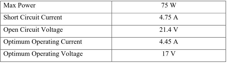
To investigate the fundamental characteristics of the PV modules, the long term measurement is ongoing. Table 2.1 indicates the specification of PV module .used for the measurements. The modules are set with the slop of 35 to 90 degrees.
Table 2.1: Specification of PV Module.
Max Power 75 W
Short Circuit Current 4.75 A
Open Circuit Voltage 21.4 V
Optimum Operating Current 4.45 A
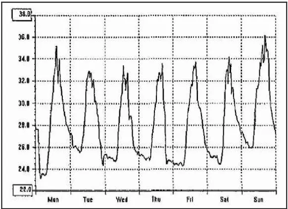
In addition the environmental factors, such as the irradiation, temperature, humidity and wind velocity are measured at the same interval by using personal computer based measurement system. In Figure 2.1 and Figure 2.2, data of ambient temperature and solar radiation were collected for every half an hour every day
. Figure 2.1: Sample Data of Solar Radiation for a Week
Figure 2.2: Sample Data of Ambient Temperature for a Week
square per day. Considering the available solar radiation, module area and angle, these parameters can derive total solar energy per day as in Equation (1).
Sep = Itotal x S x [sin (α) sin (β) + 1] (1)
Where:
Sep solar energy per day Itotal is global solar radiation S is area of PV module
α is duration available for solar energy conversion and varies between 0 o
<α <180 o, 15 ° per hour and also is a sun trajectory from the east and west.
β is a degree of PV module's angle, it varies from 0 o of the negative direction of zenith to 90 °at coordination of north and south, east and west orientation.
The amount of energy produced by a PV device depends not only on available solar energy but also on how well the device converts sunlight to the electrical energy i.e. the efficiency of the cell or module used. The conversion efficiency can be measured by the equation below:
η = ___Pmax____ x 100 (2)
Srad x Area Where:
Pmax is the maximum output power (kWh) Srad is the solar radiation intensity (kWh/m2) Area is the total area of the cell or module (m2)
Figure 2.3: System’s Block Diagram
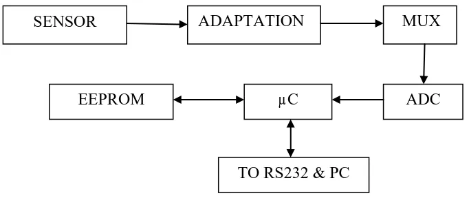
The microsystem architecture uses a microcontroller to control and monitor the data acquisition as represented in Figure 2.4. The analog part is composed essentially of one adaptation and an analog multiplexer allowing the acquisition of many meteorological parameters and the parameters related to the PV system. The numerical part of microsystem allows the transfer of data between the analog-to-digital converter (ADC) and the data bus. The treatment of data is in real time in the microsystem and the transfer of data to the pc is carried out through a bidirectional serial port using an RS232 protocol.[3]
Figure 2.4: Microsystem Architecture
The data are collected from real weather condition i.e. solar radiation, ambient temperature and humidity. At the same lime, the data also collected from PV module where all the output from PV module such voltage, current and power are recorded. These
SENSOR ADAPTATION MUX
ADC µC
EEPROM
two major parameters (weather condition and PV module monitoring) will be analyzed by ES to evaluate the best PV system model for that location.[3]
2.2 5 kW Grid Connected Photovoltaic
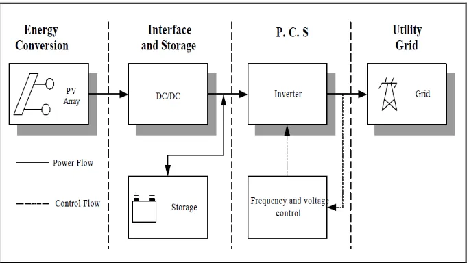
Power supply reliability and power quality have become important issues for all kind of power electronic systems including photovoltaic systems. Interconnecting a photovoltaic system with utility, it is necessary that the PV system should meet the harmonic standard and the active power supply requirement. Several utility connected photovoltaic systems have been proposed. Among these systems, the most common type is the parallel running PV with bi-directional power flow to provide unity power factor on the utility line. In this system, an inverter connected to the photovoltaic array supplies the power to the utility. Photovoltaics (PV) are the direct conversion of sunlight to electricity by solar cells. When photons of sunlight are absorbed in solar cells, the photons free electrons from the cell’s atoms, creating a voltage potential.
Figure 2.5 is a block diagram description of a PV utility-interactive system. The PCS is primarily responsible for converting the DC PV power into utility compatible AC power and for synchronizing and transferring that Ac power safety into the utility grid. The DC to AC commutated inverter utilizes the utility voltage as a means of commutation (turn-off) of transistor or thyristor switching devices.[8]