DEVELOPMENT OF AERODYNAMIC SMOKE TUNNEL UNIT FOR TEACHING AND LEARNING
AHMAD SOBRI BIN ISHAK
This technical report is submitted in accordance with the requirements of the Bachelor of Mechanical Engineering (Automotive)
Faculty of Mechanical Engineering Uuniversiti Teknikal Malaysia Melaka
ii
CONFIRMATION
“I admit that have read this work and in my opinion this work was adequate from scope aspect and quality to award in purpose Bachelor of Mechanical Engineering
(Automotive)”
Signature :……… 1st Supervisor‟s name:……… Date :………
Signature :……… 2nd Supervisor‟s name:……… Date :………
iii
DECLARATION
“I hereby, declare this thesis entitled „Development of Aerodynamic Smoke Tunnel Unit for Teaching and Learning‟
is the result of my own research except as cited in the reference”
Signature :……….
Author name : AHMAD SOBRI BIN ISHAK Date : 9 APRIL 2009
iv
DEDICATION
To my beloved late father To my beloved mother
v
ACKNOWLEDGEMENT
In the name of Allah, the Most Merciful and the Most Beneficent. It is with the deepest senses gratitude of the almighty that gives strength and ability to complete this project and technical report.
First of all, I would like to dedicate my special thanks to my supervisor, En Mohd Zakaria Bin Mohammad Nasir and also lecturers at Universiti Teknikal Malaysia Melaka because allowed to take me under his supervision. All of them has given me valuable information and ideas how to perform this project.
During to complete my project, there are many people give advises in teaching and guiding to make sure that my project success and fulfill the Faculty needed. Many things that I never know and learn before, but I got it here. So I like to say thanks to my supervisor again.
I would also to express my thanks to all the lecturers and technicians for their assistance and guidance advice in developing and producing this work and also an effort to guide me through this Projek Sarjana Muda (PSM).
vi
ABSTRAK
vii
ABSTRACT
The smoke tunnel unit is one of method to visualize the aerodynamic flow trajectory occurred on small scale vehicle model. It can also be used as an experiment apparatus to study about aerodynamic. The main goal of this project is to design the aerodynamic smoke tunnel unit (small scale) for T&L and to visualize the aerodynamic flow trajectory occurred on vehicle model using the smoke tunnel. Aiming to achieve this goal, several techniques were carried out with method. In the first phase of the case study, the step taken such as do the literatures review on the previous journal of smoke tunnel. The conclusions of this project that are the aerodynamic flow trajectory can be visualize using the smoke tunnel.
viii
TABLE OF CONTENT
CHAPTER TITLE PAGES
CONFIRMATION ii
DECLARATION iii
DEDICATION iv
ACKNOWLEDGEMENT v
ABSTRAK vi
ABSTRACT vii
TABLE OF CONTENT viii
LIST OF TABLE xi
LIST OF FIGURE xii
LIST OF ABBREVIATIONS, SYMBOLS AND SPECIALIZED NOMENCLATURE xiv
APPENDIX xv
CHAPTER 1 INTRODUCTION
1.0 Introduction 1
1.1 Objectives 2
1.2 Scope 2
1.3 Problem Statement 2
CHAPTER 2 LITERATURE REVIEW
ix
CHAPTER TITLE PAGES
2.1 Aerodynamic 3
2.2 Smoke Tunnel 9 2.3 History Of Aerodynamic Flow Visualization 10
2.4 Smoke Method 11
2.5 Smoke Generator 15
2.5.1 Probe 15
2.5.2 Power Supply 16
2.5.3 Fuel 17
2.5.4 Reservoir 17
2.5.5 The Model And Background 18
2.5.6 Operation Of The Smoke Generator 18
2.6 Flow Visualization Experiment 19
2.6.1 Smoke Flow Visualization Wind Tunnel And Equipment 19
2.7 Design Of Smoke Tunnel 22
2.8 Summary 25
CHAPTER 3 METHODOLOGY 3.0 Introduction 26
3.1 Process Planning 26
3.2 Explanation On Each Process Planning 29
3.3 Summary 31
CHAPTER 4 RESULTS 4.0 Introduction 32
4.1 Design 32
4.1.1 Contraction Cone 33
4.1.2 Settling Chamber 34
x
CHAPTER TITLE PAGES
4.1.4 Diffuser Cone 35
4.1.5 Smoke Tube 36
4.1.6 The Wind Source 36
4.1.7 Smoke Technique 37
4.1.8 Assemble Design 38
4.2 Expected Results from Air Flow Visualization Experiment 39
4.3 Summary 40
CHAPTER 5 DISCUSSION 5.0 Introduction 41
5.1 Design Process 41
5.2 Fabrication Process 42
5.3 Expected Results 42
CHAPTER 6 CONCLUSION AND RECOMMENDATION 6.0 Conclusion 43
6.1 Recommendations 43
REFERENCES 44
xi
LIST OF TABLES
No. TITLE PAGE
xii
LIST OF FIGURES
No. TITLE PAGE
2.1 The picture shows the streamlines over the vehicle body 4
2.2 Pressure and speed 5
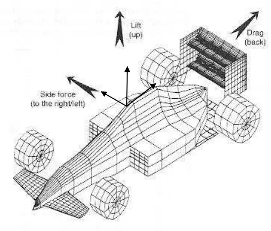
2.3 Aerodynamic forces 6
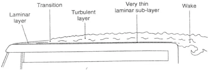
2.4 Boundary layer growth on the roof of a bus 7
2.5 Laminar Flow 8
2.6 Turbulent Flow 8
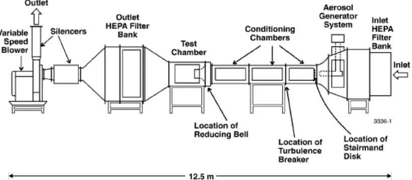
2.7 Schematic diagram of the Lovelace aerosol wind tunnel 9 2.8 Low turbulence subsonic smoke-tunnel with unsteady
flow generator 10
2.9 An example of smoke produced in smoke tunnel 12
2.10 Schematic of smoke rake with vertical movement used
for subsonictunnel 14
2.11 The schematic diagram of the smoke generator 16
2.12 Dual unit power package 17
2.13 Smoke Flow Visualization Tunnel 20
2.14 Preston-Sweeting Generator Mist 21
2.15 Models use in the smoke tunnel 21
2.16 Sample smoke flow visualization for the airfoil model 21
2.17 HM 170 Educational Wind Tunnel 22
2.18 Model H-6910-CDLWind Tunnel 22
xiii
2.20 Educational Wind Tunnel (EWT) System 24
A Semester I 27
B Semester II 28
4.1 Contraction cone 33
4.2 Settling chamber 34
4.3 Test section 35
4.4 Diffuser Cone 35
4.5 Smoke Tube 36
4.6 Smoke Tunnel in 2D view 38
4.7 Smoke Tunnel in 3D view 38
4.8 The flow visualization over the vehicle model in
smoke tunnel 39
4.9 The flow visualization over the vehicle model in
xiv
LIST OF ABBREVIATIONS, SYMBOLS AND SPECIALIZED NOMENCLATURE
AC = alternating current
CFD = Computational Fluid Dynamic CD = drag coefficient
F = Fahrenheit ft3 = feet cubic lbs = pounds m3 = meter cubic mph = miles per hour
psi = pound per square inch � = air pressure
� = air density µm = micrometer
� = speed.
xv
APPENDIX
NO. TITLE PAGE
A Gantt Chart Semester I 46
A Gantt Chart Semester II 46
B Contraction Cone Drawing 47
C Test Section Drawing 48
D Diffusion Cone Drawing 49
E Smoke Tube Drawing 50
F Sample of Aerodynamic Flow Visualization
1
CHAPTER 1
INTRODUCTION
1.0 Introduction
Aerodynamic is important factor consider in design stage. Though the term "aerodynamics" is most commonly associated with airplanes and the overall science of flight, in fact, its application is much broader. Simply put, aerodynamics is the study of airflow and its principles, and applied aerodynamics is the science of improving manmade objects such as airplanes and automobiles in light of those principles. Aside from the obvious application to these heavy forms of transportation, aerodynamic concepts are also reflected in the simplest of manmade flying objects and in the natural model for all studies of flight, a bird's wings.
The smoke tunnel is one of method to visualize the aerodynamic flow trajectory occurred on small scale vehicle model. This equipment designed to help the lecturer to visualize and explain about aerodynamic effect on frontal edge or etc. Student will know and learn the term practically to support the theory or simulation (CFD). This equipment will be used as a practical lesson through experiment in order to compare theoretical with simulation.
2
1.1 Objectives
To design the aerodynamic smoke tunnel unit (small scale) for T&L.
1.2 Scope
Literature study on standard smoke tunnel and aerodynamic effect. Design an appropriate scale and concept for measure and
experimental purpose.
Drawing design of the smoke tunnel using Engineering Tools (Catia VR16).
Data comparison from experiment expected result with theory (using present CFD result).
1.3 Problem Statement
3
CHAPTER 2
LITERATURE REVIEW
2.0 Introduction
This literature review is discussed about research which had been made previously about smoke tunnel. It also discussed the points which related to this project such as smoke tunnel design and aerodynamic flow trajectory. The objective of the literature review is to appreciate and explain in detail about journal read as the guideline for this project research. All information about wind tunnel can also be use because it is not much differing from smoke tunnel. Since the current project is to design an experiment for aerodynamic flow visualization, all the information regarding aerodynamic, wind/smoke tunnel, CFD and any related information should be collected.
2.1 Aerodynamic
4
acting on the object. Typical properties calculated for a flow field include velocity, pressure, density and temperature as a function of position and time. By defining a control volume around the flow field, equations for the conservation of mass, momentum, and energy can be defined and used to solve for the properties. The use of aerodynamics through mathematical analysis, empirical approximation and wind tunnel experimentation form the scientific basis for heavier-than-air flight.
Figure 2.1: The picture shows the streamlines over the vehicle body. (Source: www.kasravi.com)
5
Figure 2.2: Pressure and speed. (The air accelerates when flowing from a high pressure to a low one and slows down when flowing from a low pressure to a high
one). (Source: Barnard, 2001)
There is one relationship that is absolutely fundamental to the study of air flows and that is the Bernoulli equation. Bernoulli‟s equation can be written as below:
� + 1
2 ��
2 = constant………(1)
where � is the pressure,� is the density and � is the speed.
There are three pressure related to aerodynamic, that are static pressure, dynamic pressure and stagnation pressure. Static pressure is air pressure at any point while dynamic pressure actually represents the kinetic energy of a unit volume of air (m3 or ft3). Dynamic pressure represented as 1
2 ��
2 in mathematical symbol.
Aerodynamic forces such as lift and drag are directly dependent on the dynamic pressure. At any point in the flow where the speed is zero (the lowest possible value), the pressure must reach its maximum value because this maximum pressure is associated with stagnant condition (zero flow speed). It is known as the stagnant pressure. In the context of cooling air flows and engine air intakes, the stagnant pressure is commonly referred as the ram air pressure.
6
Figure 2.3: Aerodynamic forces. (Source: www.kasravi.com)
normal road vehicles is the drag force. The total force resisting the forward motion of a road vehicle comes partly from the rolling resistance of the wheels and partly from aerodynamic drag. The aerodynamic drag dominates at speeds above about 65-80 km/h (40-50 mph) and there are considerable economic and performance advantages to be gained from drag reduction. Drag coefficient ( ) is mainly dependent on the shape of the vehicle. The aerodynamic drag also depends on the frontal area of the vehicle, the air density and the square of the relative air speed. The relationship between drag and these factors can be expressed by:
Drag = 1 2 ��
2� ………(2)
where � is the frontal area
� is the density of the air
� is the speed of the vehicle relative to the air
Knowing the drag coefficient and the projected frontal area, formula above can be used to work out the drag at any speed. Unfortunately, drag coefficient also dependent on a Reynolds number (���/�). The dependence on Reynolds number
7
wind tunnel that the variation of with Reynolds number becomes important. The lower value of means the car has larger frontal area. As an example, VW Microbus has 0.45 value of compared to F1 car is 1.00 value of . (Table 2.1)
Table 2.1: CD and CDA values for various vehicles. (Source: Barnard, 2001)
Figure 2.4 shows how the boundary layer grows on the surface of a vehicle. There are two distinctive types of boundary layer flow. Near the front edge, the flows smoothly with no turbulent perturbations and appear to behave like laminae sliding over each other with friction, the outer ones moving faster than the inner ones. This type of flow is called laminar flow. Further long, there is a sudden change or transition to a turbulent type in which random motion is superimposed on the average flow.
8
Figure 2.5: Laminar Flow. It has the ideal aerodynamic properties. (Source: www.kasravi.com)
Figure 2.6: Turbulent Flow. It has undesirable properties. (Source: www.kasravi.com)
The two types of boundary layer flow (Figure 2.5 and Figure 2.6) have important differences in their properties and these can be exploited in aerodynamic design. The main practical effects are that the laminar layer produces less drag due to friction with the surface but in a turbulent boundary layer, the flow is more likely to follow the contour of the body which usually results in lower „pressure drag‟.
9
2.2 Smoke Tunnel
Smoke tunnel is an apparatus for studying the interaction between a solid body and an airstream. Normally smoke tunnel is used to visualize flow trajectory occurred on the vehicle model. A smoke tunnel simulates the conditions of a vehicle in moving by causing a high-speed stream of air to flow past a model of the vehicle being tested. Applications of smoke tunnel research range from testing of airframes (the structures of aircraft and spacecraft) to research on the boundary layer, turbulence, drag, and lift. Measurements of air pressure and other characteristics at many points on the model yield information about how the total wind load is distributed. This can be done by injecting thin streams of smoke into the tunnel to render the airflow visible. A mixture of lampblack and kerosene painted on the model shows the surface streamlines. A suspension of talcum powder and a detergent in water is also used. Pressures on the model surface are measured through small flush openings in its surface. Forces exerted on the model may be determined from measurement of the airflow upstream and downstream of the model. In many instances, smoke tunnels have been rendered obsolete by computer modeling. Figure 2.7 shows an example of smoke tunnel in marketplace.