UNIVERSITI TEKNIKAL MALAYSIA MELAKA
STUDY A PNEUMATIC CONTROL SYSTEM AND SIMULATION
FOR INSECT WALKING ROBOT
This report submitted in accordance with requirement of the Universiti Teknikal Malaysia Melaka (UTeM) for the Bachelor Degree of Manufacturing Engineering
(Robotic and Automation) with Honours.
by
SYAMSUDDIN BIN ABD AZIZ
DECLARATION
“I declare this report is on my own work except for summary and quotes that I have mentioned its sources”
Signature :
Name of Author : SYAMSUDDIN BIN ABD AZIZ
APPROVAL
This report is submitted to the Faculty of Manufacturing Engineering of UTeM as a partial fulfillment of the requirement for the degree of Bachelor of Manufacturing Engineering (Manufacturing Design) with honours. The member of the supervisory committee is as follow:
i
ABSTRACT
ii
ABSTRAK
Dalam rancangan ini, objektif utama adalah untuk mempelajari dan merancang suatu sistem kawalan pneumatik untuk robot serangga berjalan. Kebiasanya, robot serangga berjalan seperti hexapod menggunakan motor stepper untuk menggerakkan kaki dan menunjukkan pergerakan yang dibuat. Pergerakan robot berjalan lebih penting bagi setiap robot tidak kira sama ada robot serangga, robot berkaki dua roda atau berjalan seperti dari segi jumlah gaits dan darjah kebebasan (DOF). Untuk membuat pembaikan untuk robot ini, sistem pneumatik akan digunakan dan menunjukkan pergerakan mekanisma bagaimana ia bekerja atau bergerak. Dalam mereka rangka robot serangga berjalan dalam keadaan lancar, litar kawalan pneumatik diperlukan dari segi pergerakan dan kriteria logik. Sistem kawalan robot menggunakan cara berjalan jenis tripod gait.
iii
DEDICATION
vi
ACKNOWLEDGEMENT
I would like to dedicate my appreciation to my lecturer, En. Khairol Anuar bin Rakiman for serving as my supervisor and for providing guidance while conducting the research and the writing of this Projek Sarjana Muda (PSM).
Thank you also goes to my entire lecturers especially my academic advisor, Pn. Silah Haryati binti Kamsani for her advices and guidance since the first day I step in UTeM. Furthermore, I would like to offer thanks and deepest gratitude from the bottom of my heart for all the support, encouragement and inspirations I obtained through the duration of this project.
v
1.2 Insect Walking Robot 1
1.3 Problem Statement 3
1.4 Project Aim and Objective 3
1.5 Scope 4
2.3.2 Advantages of Pneumatic Actuator 9
2.4 Control System Use in Project 10
2.4.1 PLC 11
2.5 Software Design Use in Project 11
2.5.1 Solid Works 12
vi
2.6 Walking Robot Available in the Market 13
2.6.1 Humanitarian Mine Detection Six-Legged Walking
Robot COMET- II with Two Manipulators 14 2.6.2 Intelligent Legged Climbing Service Robot for
Remote Inspection and Maintenance in Hazardous Environments 15
2.6.3 Six-Legged/Wheeled Security Robot 16
2.6.4 Dash: A Dynamic 16g Hexapedal Robot 17
2.6.5 Maneuvering of a Biologically Inspired Hexapedal Robot 18 2.6.6 Design of an Autonomous Mini Mobile Robot Able
To Interact With Cockroaches 19
2.6.7 Development of Neural Oscillator Based Motion
Control System and Applied To Snake-Like Robot 20 2.6.8 A Small, Insect-Inspired Robot That Runs and Jumps 21 2.6.9 A Cockroach-Inspired Hexapod Robot Actuated By LIPCA 22 2.6.10 A Small, Autonomous, Agile Robot with an
On-Board, Neurobiologically-Based Control System 23 2.6.11 Architectures for a Biomimetic Hexapod Robot 24
2.7 Conclusion 25
3. METHODOLOGY
3.1 Background 26
3.2 Project Design and Analysis 27
3.3 Preliminary Conceptual Design 28
3.4 Method of Gait Generation 30
3.5 Methods of Leg Movement 31
3.6 Gait Type Selection 33
3.7 Step Phase Gait 33
3.8 Conclusion 34
4. PNEUMATICALLY A CONTROL INSECT WALKING ROBOT DESIGN
4.1 Introduction 35
4.2 Mechanical Design 35
vii
7.1 Recommendation for Improvement 64
REFERENCES 65
APPENDICS
A Insect Walking Robot Drawing B RC Servo Motor
C Legged Robot Design 3
ix
LIST OF TABLES
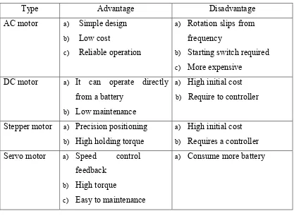
2.1 Type of Motor 7
2.2 Advantage of Pneumatic Actuator 9
2.3 Description of Humanitarian Mine Detection 14
2.4 Description of Intelligent Legged Climbing Service Robot 15
2.5 Description of Wheeled Security Robot 16
2.6 Description of a Dynamic 16g Hexapedal Robot 17
2.7 Description of a Biologically Inspired Hexapedal Robot 18 2.8 Description of a Design of an Autonomous
Mini Mobile Robot Able To Interact With Cockroaches 19 2.9 Description of Development of Neural Oscillator
Based Motion Control System and Applied To Snake-Like Robot 20 2.10 Description of a small, insect-inspired robot that runs and jumps 21 2.11 Description of a Cockroach-Inspired
Hexapod Robot Actuated By LIPCA 22
2.12 Description of a Small, Autonomous,
Agile Robot with an On-Board, Neurobiologically-
Based Control System 23
2.13 Description of Architectures for a Biomimetic Hexapod Robot 24
4.1 Advantage and Disadvantage for Conceptual Design 1 38 4.2 Advantage and Disadvantage for Conceptual Design 2 40 4.3 Advantage and Disadvantage for Conceptual Design 3 41
4.4 Pugh Method 43
x
LIST OF FIGURES
2.1 An example of DC motor 6
2.2 A pneumatic component 8
2.3 Model DSEU FESTO pneumatic cylinder 10
2.4 The connection between PLC, programming,
push button, pump, photo sensor and drive motor and light 11
2.5 A third dimension view of SolidWork drawing 12
2.6: Library and Cross Section views synchronized with a component 13
2.7 Overview of COMET-II 14
2.8 Robug IIs was performing an automatic floor to wall transfer 15
2.9 Six-legged/Wheeled Robot 16
2.10 DASH: A power Autonomous Hexapedal robot 17
2.11 Sprawlette, a hexapedal running robot guided
by a simple tactile sensing artificial antenna 18
2.12 InsBot fully assembled 19
2.13 The developed snake like robot 20
2.14 Mini-Whegs™ 9J and a 10.4 cm long robot that runs 21 2.15 Prototype of the LIPCA robot is the largest part
of the robot, thus its size influences overall dimension of the robot 22 2.16 BILL-Ant- walks autonomously on irregular terrain
using SCASM leg control implemented using
low-computation-capable microcontrollers 23
2.17 Biobot, a biomimetic robot physically modeled
after the American cockroach, Periplaneta Americana 24
3.1 Flow Chart of the project design and analysis phase 27
3.2 Top View 28
3.3 Right View 29
xi
3.5 Legged movement 30
3.6 Examples of all hexapod gaits completing one full cycle 33 3.7 Hexapod gaits completing one full cycle for insect robot 34
4.1 Legged labeling 36
4.2 Flow Process to Select the Best Design 37
4.3 Pneumatic Insect Walking Robot First Design 38
4.4 Pneumatic Insect Walking Robot Second Design 40
4.5 Pneumatic Insect Walking Robot Third Design 41
4.6 Robot leg (a) and (b) show normal condition of legged design1 44 4.7 Robot leg design 1 with both of actuator in operation 45 4.8 Robot leg design 1 with one of actuator in operation 45 4.9 Robot leg show normal condition of legged design 2 46 4.10 Robot leg design 2 with both of actuator in operation 46 4.11 Robot leg design 2 with one of actuator in operation 47 4.12 Robot leg (a) and (b) show normal condition of legged design 3 47 4.13 Robot leg design 3 with both of actuator in operation 48 4.14 Robot leg design 3 with one of actuator in operation 48 4.15 Pneumatic cylinder position design for forward
and backward process 50
4.16 Pneumatic cylinder circuit diagram for forward
and backward process 50
4.17 Pneumatic cylinder ladder diagram for forward
and backward process 51
4.18 Pneumatic cylinder position design for right and left direction 52 4.19 Pneumatic cylinder circuit diagram for right and left direction 53 4.20 Pneumatic cylinder ladder diagram for right and left direction 53
5.1 Volume of Walking Robot 55
xiii
LIST OF ABBREVIATIONS
PSM - Projek Sarjana Muda
UTeM - Universiti Teknikal Kebangsaan Malaysia COG Center Of Gravity
1
CHAPTER 1
INTRODUCTION
1.1 Background
In this chapter will describes and simple briefly about the design a pneumatic control system for insect walking robot. In this chapter also include the problem statement of the design for insect walking robot, objective of this project, research scope, and lastly important of the research.
1.2 Insect Walking Robot
Insect walking robot is combination between insect nature and mechanical robotic technology. Most walking machines follow the animal locomotion by using a high number of similar legs with many degrees of freedom (DOF). This approach leads to complex design needs a complex control system that use static walking. Static walking at least are listed six legs or more are required.
2
However, there are many different types of insect walking robots from bipeds or human of different joint configurations and intelligence, to walking animal like quadrupeds, many legged insect styles and even snake emulating robots. The basic components of a robot are:
a) Moving parts that perform an action like arms and legs.
b) An actuator to power moving parts and sensors to detect environment. c) A control system that makes decisions and overlooks the overall operation.
Most often, any robot such as human robot or insect robot are controlled by gaits, which allow the robot to move forward, turn, and perhaps side-step. Some of the most common gaits are as follows as alternating tripod with 3 legs on the ground at a time, quadruped, and also crawl to move just one leg at a time. Beside, gaits for insect walking robot are often stable, even in slightly rocky and uneven terrain. This is because gait is characterized as the sequence of lift and release events of the individual legs is depend on the number of legs and also the number of possible event N for a walking machine with k leg is (Sven, B., 2000):-
N= (2k-1)!
(1)
where:
3 1.3 Problem Statement
Robot is a relatively modern technology at this time. At present this technology is exposed to some countries, particularly in developed countries. European countries such as Germany, USA and other country have done develop robotic technology in this century. This technology to produce a lot of robots, especially robotic insects, swarm robots, robot military, delivery robots, industrial robot and more. At this time, the system used by the insect robot mostly used a motor such as stepper motor but the insect robot using a pneumatic system is not much highlighted or introduced especially in this country.
However, in robot technology research institution of higher learning is not much to introduce the robot to walk using a pneumatic system and effectively simulation -motion. So, with the graphic simulation of the robot, students will better understand the movements a more effective for sequence mechanism simulation performed by using the pneumatic system just in a prototype or developed.
1.4 Objective
The aim of this project is to design an insect walking robot in smooth motion in graphic simulation software. Below are some important objectives that need to be achieved.
a) To develop graphic simulation on insect walking 6 legs robot using CAD software. b) To design pneumatic control system circuit in term of sequential and logic criteria
4 1.5 Scope
Study the mechanism of insect walking robot. As well as project focused on insect walking robot is:
a) Identify the suitable gait into insect walking robot.
b) Develop an interactive insect walking robot simulation by using SolidWorks. c) Design pneumatic control circuit system for insect walking robot.
d) Analyze the pneumatic system calculation such as velocity, air cylinder flow rate and also sizing of air reservoir.
e) Carry out analysis on possible load and weight for pneumatic components of insect walking robot.
1.6 Project Planning
The project planning is needed to identify and to make plan in order to achieve the objectives in a period of time was prescribed. A good planning would ensure this project goes on actual track. For a good time management planning, Gantt chart is a suitable method that always being used.
A Gantt chart is a type of bar chart that illustrates a project schedule. The Gantt charts illustrate the start time and the end of the project implementation and summary elements of a project. Project implementation and summary of a project element comprise the work breakdown structure of the project.
5
CHAPTER 2
LITERATURE REVIEW
2.1 Background
This chapter will discuss and review available literature on Design Pneumatic Control System for Insect Walking Robot using Automation Studio and CAD software. The reviews begin with Walking Robot. This section will be including the actuator of system, control system, design and also previous projects. Then, the Automation Studio and CAD software will be discussed in this chapter.
2.2 Actuator
6
2.2.1 Electrical Motor
Electrical motor is a device which it convert electrical energy to mechanical energy following the principles of process by generator. Energy of motors used on the part and the device always perform both task and related with actuation and movement. Many type of electric motor can be run as a generator or vice-versa. Basically electrical motor can be use in alternating current (AC) and also direct current (DC) for any application. The DC motor is different from AC motor because it uses electricity and magnetic field to form what is known as torque. Both categories are further divides into different subcategories according their function (Puchstein 1976)
Figure 2.1: An example of DC motor (www.o-digital.com)
2.2.2 Types of Motor
7
8
Figure 2.2: A pneumatic component (www.instruction.greenriver.edu)
2.3.1 Actuator Type Used in Project
Pneumatics cylinders double acting is used in this project because to perform their function and give a force by converting the potential energy of compressed gas into kinetic energy. So that, this actuator will be attach to all legged of insect walking robot and to make sure the function is running better.
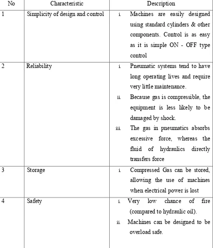
9 2.3.2 Advantages of Pneumatic Actuator
Table 2.2: Advantage of pneumatic actuator
No Characteristic Description
1 Simplicity of design and control i. Machines are easily designed using standard cylinders & other
ii. Because gas is compressible, the equipment is less likely to be damaged by shock.
10
Figure 2.3: Model DSEU FESTO pneumatic cylinder
2.4 Control System Use in Project
Robots use a computer, microcontroller or a microprocessor and also PLC to manage movement and action. Like all computer, the ones for robot control need to be
programmed. Although the advantage of programming languages such as functional,
logic or functional logic languages for a high level completion of software systems is well known, the effect of such languages are too many actual world applications is imperfect. One reason for this might be the fact that many real world applications have not only a logical component but demand also for an appropriate modeling of the dynamic behavior of a system.