ToGouR: Tour Guide Robot Visualization
using Shape Recognition Pattern for
Automatic Navigation
Hamzah Asyrani Bin Sulaiman, Mohd Zulfadhli Akmal Subari, Muhamad Arif Bin Pazil, Mohd Muzafar Bin Ismail, Maizatul Alice Binti Meor Said
Faculty of Electronic and Computer Engineering Universiti Teknikal Malaysia Melaka 76100 Durian Tunggal, Melaka, Malaysia
Abstract—The invention of autonomous robots with an increasing demand for industrial used has been caught attention from researchers and inventors. In this new sophisticated era, various types of robots and systems have been developed and bring significant contribution to the industries, economy, and infrastructure. Thus in this project, we have develop an application for PIC based Tour Guide Robot (ToGouR) where the PIC16F877A has been chosen as the main microcontroller. The application has a Graphical User Interface (GUI) has allows the user to interact in interactive ways between ToGouR and the images for navigation systems. The application also has an ability to perform shape recognition for path planning and automatically make alternative ways when various shapes that have been recognized are put in the way. Various alternatives have been used to make sure this project is successful carried out. This tour guide robot is suitable to be commercialized with numerous robotics companies that would like collaborate in delivering this project as a product and can be used for military or during any unexpected catastrophe such as one that occurred in Japan.
Keywords-component; robot, shape recognition, pattern
I. INTRODUCTION
Recently, many researches have been done in Japan, Korea, Germany, Switzerland, and America regarding the tour-guide robots that has multiple functions, features, and appearances. With the bombarding type of robots, most of these robots have been found in the public such as various museums, recreation parks and other public places [1-17]. In World Expo 2005 Aichi, we have the reception-tour guide robot that showed us the significant contribution of tour-guide robots to the community.
Nowadays, we can see that tour guide is important to our country. For tourist that wants to do their research might visit some company or institute to get information. Because of this, the company faced problem to entertain tourist. To ensure visitors or tourist satisfied with their serve, they have spare time for them. But totally of employee busy with their work. To solve this problem our group decides to design a tour guide robot called as ToGouR. This robot is move in automatically system with a several backup system to avoid failure or emergency. ToGouR will be waiting for visitors in a starting point or initial position that have been decided. The visitors or tourist just need to key in their destination that displayed on a GUI screen that have been installed [10, 12]. ToGouR will guide the visitors to their destinations.
The robot will be installing with a wireless camera, to get a view that will be displayed on a monitor. It is also can be controlled by manual in case the robot having a difficulty on the trip. The robot also will be installed with 3 sensors to improve the movement of robot and to ensure that ToGouR move in good condition. This robot also can return to the initial position and wait other instruction.
II. RESEARCH BACKGROUND
III. RESEARCH METHODOLOGY
A. Introduction
This chapter will explain more about the project methodology that used in the project. This part will explain more about the project path from the beginning until it is completed. Every single thing that has been done in this project should be explains step by step. This project methodology must be done in order to make sure this project that consists of software and hardware development will be deployed systematic.
B. Project Flowchart
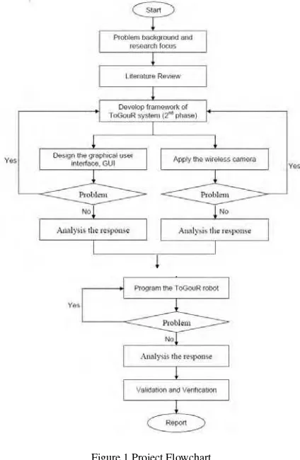
This research consists of three main phases (Figure 1). First phase involve the research focus and problems background regarding tour guide robot which using power line networking system. In this phase, the literature review on various types tour guide robot in market, method that being used in the tour guide robot, codes for the robot and interaction between human and robot from various resources including journals, books and other reference was conducted. The aim for the reading was to get some idea on how to make some improvement or enhancement of features previous tour guide robot types that already been developed in the market.
Second phase involve programming and implementing of propose technique via MPLab IDE and Visual Studio 2010 as a platform for the robot to function and as its main brain. Starting with the development of the graphical user interface, the robot now can interact with the human. Then performance and destination of the robot being monitor via the graphical user interface and integrated wireless camera. In this phase also the ToGouR will be programmed. In order to make sure that the codes are function properly, the obtained result will be analyzed which is considered as the last part. The purpose of doing analysis of the response is to make sure that there is no error and the coding functioning properly. The outcome of this testing result based will be collected and analyzed for future research in order to implement any enhancement or improvement that appropriate for the real-time application.
Figure 1 Project Flowchart
IV. FEASIBILITY STUDY FOR FREQUENCY INTERFERENCE OF WIRELESS CAMERA
From our concern, a signal from a 2.4 Ghz Wireless Camera might have interfered signal by any 2.4 Ghz frequency devices such as cordless phone or mobile phone but not all the time. The visual still can be viewed from our monitor even though the interference occurred but may lost certain quality of the visual. It is because we performed a connection between specific IP address just to transmit the signal and avoid worse case scenario of getting lousy visual from the wireless camera. Usually we used Line-of-Sight(LOS) to rate the signal quality of Wireless Camera. Standard Wireless Video Camera might have an average of about 700 feet LOS.
In general, the signal also can be transmitted through any solid objects such as plastic, wood, glass or fiberglass regardless of the materials but has different capability of signal interference.
V. IMPLEMENTATION OF A TOUR GUIDE ROBOT VIA SHAPE RECOGNITION AND PATH PLANNING
Based on the paper that written by Chun-Chieh Wang, Kuo-Lan Su and Chih-Teng Shen from Chienkuo Technology University and National Yunlin University of Science & Technology proposed an implementation of a tour guide robot with image system is implemented [3]. “This paper also proposed a shape recognition method so that the robot can move autonomously. In addition, to abandon the conventional rail-type tracking control, we propose a fixed path planning to let the robot move autonomously along the desired path. Moreover, the supervisors can look after the security of the environment by a human machine interface surveillance system. The validity of the proposed shape recognition method is verified by means of a practical testing on a tour guide robot with POB system. The experimental results validate the practicality of the shape recognition and the path planning technology applied to robots.” In the shape recognition part, there are 3 things that need to be considered about pixel, POB-eye and POB-pattern. For the pixel configuration part, a black and white LCD screen is used where color pixel is represented by one bit. Screen displays will eventually show one byte for 8 pixels as shown in Figure 2.
Our challenge for this buffer to have a ration of “1 bit = 1 pixel”. As it does not consume too much memory, 1 bit = 1 pixel is the suitable operation. A mask is required in order to change a bit value in the memory. This mask will be used to differentiate whether the bit is set to 0 or to 1. Since the process is time consuming as it takes 8129 times just to determine the mask, the usage of 1 bit = 1 pixel is needed to save memory and computation time. Another approach is to design a system that is able to consider 1 byte to draw 1 pixel. The advantage of this technique is that it can have no delay or mask when we are requires to switching on or off the pixel. However, it may takes up to 8 times of memory than the previous technique. For shape recognition, we need to transfer 2-D array into only 1-D array as shown in Figure 3.
Fig. 2 2-D Array [3]
Fig. 3 D Array1 [3]
A. Navigation Method
The navigation methods that will be used in this project are combination of shape recognition and selection destination. The concept of shape recognition method is to make an autonomous movement of the robot after visitor selects the desired destination. After the visitor has select the desired destination, a fixed path planning is generated by the robot in order to let the robot move accordingly in autonomously along the planned path configured by the robot. In order to have some sort of emergency situation, a robot supervisor can have a vision and full control of the robot in a control room. In details, the robot can recognize shape that installed at certain location such as walls and floors in order to find their ways. A command already installed in the robot system for the recognition purpose and they can generated automatically an alternative ways when reach obstacles.
the movement. The working principle of the robot is after user clicks the destination at the system, the robot will move to the destination and follow the shape guidance along the operation. This guide robot also will be including the manual transmission so that if there is any malfunction in the autonomous transmission, the robot still can operate.
Fig. 4 Shape for Tour-Guide Robot
B. Image Transmitting to the control unit
A basic decision that needs to be made is whether or not to invest in a wireless system. Unlike their hardwired counterparts, wireless systems use a transmitter and receiver to send data from the camera to control unit. One advantage of a wireless camera is flexible placement. A wireless camera can be moved to different locations so long as a line of sight relationship remains between the transmitter and the receiver. In other words, the transmitter and receiver must be able to see each other. This is the only stipulation besides the actual range of the equipment. In order to move a hardwired camera, power and video cables must be run to the new location. A second advantage related to the first is that wireless cameras are perfect for seasonal or temporary applications.
Once the application or season has ended, the camera can be removed from the location. A third advantage is the appearance of the system. With no messy cabling to install, a wireless system is more aesthetic than a hardwired system. Relative to this is the fact that there are no wires that can be tampered with or cut in a wireless system. While using wireless camera also need to be considered for the frequency interference which the signal generated by a 2.4GHz Wireless Camera may be disrupted by the 2.4GHz cordless phone or other 2.4 GHz devices but not every time. Even there is an interference the visual from the camera will receive by the receiver. It is because the wireless cameras are using a specific IP address to transmit the signal. The transmission range of a Wireless Camera is usually rated by use the Line-of-Sight (LOS). Standard Wireless Video Cameras have a range of about 700 feet LOS. So there will be no problem for ToGouR wireless camera to transmit visual image to receiver.
C. Camera Configuration
In order to install the IP camera, there are 12 steps for user to follow. The first step is the language selection. There are various selections of languages such English, French and others, so English is the best selection to set as default. Second step is the Wi-fi protection setup (WPS) for router. The WPS is to able creating a secure wireless connection between camera and router and the best choice is to choose no WPS connection. Next is the hardware setup and followed by Ethernet cable and power adapter connection. The camera selection will be enabled if the LED on the camera is green light. In order to use view the camera without an internet connection, choose Intranet connection. After all the steps had been followed and camera been configured successfully, the user can stream the image on the camera. Figure X-X explains the steps.
D. Software Development
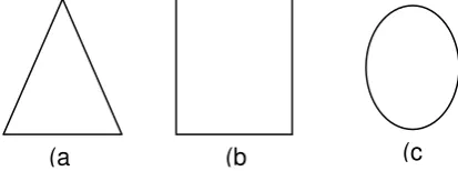
In software development, there are 5 forms that being used in order to complete this project, from the control form, simulation form, virtual serial port emulator, wireless camera form and shape recognition form. Furthermore, this software was developed with the combination of C-language such C# and C for the control form such main form and shape recognition form and been designed using Visual Studio 2010. For the simulation form, the circuit was designed using Proteus 7. In the control form, there are connect and disconnect function in order to communicate with the robot using Bluetooth protocol and selection of mode either auto or manual mode also been developed in this control form. Comparing between manual mode and auto mode, the manual mode will help us to control the robot under certain unavoidable conditions differ than auto mode that the robot will be headed to the guided direction according the black line painted at the floor and stop whenever it reaches certain checkpoints. The simulation form, which is the circuit form, consists of all components that are used for functioning the robot. Meanwhile, in simulation and control form can’t be communicated without connecting the serial port. In order to communicate the simulation form and control form, the virtual serial port emulator must be activated. The purpose of wireless camera form is to enable admin or user to watch what the robot currently travels. Lastly the shape recognition form was designed to allow visitor to choose which destination to travel. There are 4 destinations include in this form such home is represented by no shape, destination 1 is represented by circle shape, destination 2 is represented by rectangular shape and destination 3 is represented by triangle shape. This shape recognition form was designed for the auto mode.
VI. TOUR GUIDE ROBOT TESTING
The robot will be headed to the guided direction according to the black line painted at the floor and stop whenever it reaches certain checkpoints. For the Auto mode, there are consist of Home button, Reset position, stop and back button. Here also shape will be recognized.
A. Destination: Home
Figure 5 shows the result of auto mode for home destination. For home, user just pressed the Home button at the GUI and the ToGouR will start to move. Noted that when home is being chose, the GUI will show Current Destination : 0 and Current Shape : No shape, this is represent the Home destination. The Bluetooth will receive a signal from the user and then transmit the signal back to the microcontroller that works as the brain of the robot to declare it is a home destination and move the robot until it reached the checkpoint and LCD will displayed the direction of the robot.
Fig. 5 Destination : Home
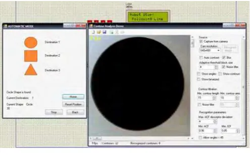
B. Destination 1: Circle
Figure 6 shows the result of auto mode for destination 1. For destination 1, user showed the circle shape to the camera at the shape recognition form and the ToGouR will start to move. Noted that when destination 1 is being chose, the GUI will show Current Destination : 1 and Current Shape : circle, this is represent the destination 1. The Bluetooth will receive a signal from the user and then transmit the signal back to the microcontroller that works as the brain of the robot to declare it is a home destination and move the robot until it reached the checkpoint and LCD will displayed the direction of the robot.
Fig. 6 Destination 1
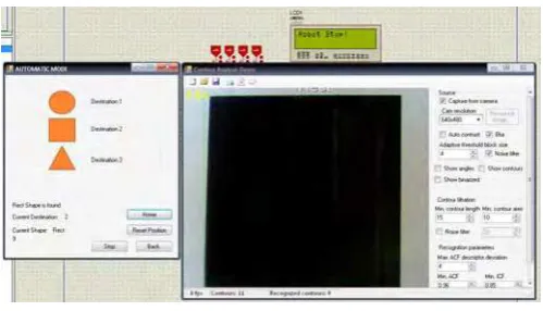
C. Destination 2: Rectangle
Fig. 7 Destination 2
D. Destination 3: Triangle
Figure 8 shows the result of auto mode for destination 3. For destination 3, user showed the triangular shape to the camera at the shape recognition form and the ToGouR will start to move. Noted that when destination 3 is being chose, the GUI will show Current Destination : 3 and Current Shape : tri, this is represent the destination 3. The Bluetooth will receive a signal from the user and then transmit the signal back to the microcontroller that works as the brain of the robot to declare it is a home destination and move the robot until it reached the checkpoint and LCD will displayed the direction of the robot.
Fig. 8 Destination 3
VII. CONCLUSION AND FUTURE WORK
The final outcome of the project is to design an application for a guide robot system for via shape recognition to autonomous guide visitor to the desired location. By using the shape recognition as the navigation method will move the robot autonomously and implemented wireless camera to view the movement of the robot. Besides that the streaming video of the robot can be displayed and saved in the graphical user interface in the control unit. All the knowledge studied in pass few years can be fully utilized and recalled back by doing this project. This project has discussed on the design and develop a transceiver with more robust. Research has been done on base on the problem statements and comes out with the idea to complete the project.
This system can be right foundation for further improvement in the future. Therefore, there are several actions can be made for improvement this project features for the future such change navigation method from shape recognition to motion detection for an example. Besides that the project will be more interactive if it can guide visitor at every floor in the building. Meanwhile this tour guide robot feature only can guide visitor in one floor. In addition, the application of shape recognition can be used in certain area for example in factory; the restricted area can be identified using certain shape. It can be used for military or during any unexpected catastrophe such as one that occurred in Japan. They used various helps from various robot companies to search for the survivors and for nuclear factory. It has very high commercialization value with numerous robotics companies that would like collaborate with us in delivering this project as a product.
ACKNOWLEDGMENT
REFERENCES
[1] H. Byung-Ok, K. Young-Ho, C. Kyusung, and H. S. Yang, "Museum tour guide robot with augmented reality," in Virtual Systems and Multimedia (VSMM), 2010 16th International Conference on, 2010, pp. 223-229.
[2] T. Ching-Chih, S. Shu-Min, H. Hsu-Chih, W. Min-Yu, and L. Chih Chung, "Autonomous navigation of an indoor tour guide robot," in
Advanced robotics and Its Social Impacts, 2008. ARSO 2008. IEEE Workshop on, 2008, pp. 1-6.
[3] W. Chun-Chieh, S. Kuo-Lan, and S. Chih-Teng, "Implementation of a Tour Guide Robot via Shape Recognition and Path Planning," in Innovative Computing, Information and Control (ICICIC), 2009 Fourth International Conference on, 2009, pp. 544-547.
[4] T. Germa, F. Lerasle, P. Danes, and L. Brethes, "Human / robot visual interaction for a tour-guide robot," in Intelligent Robots and Systems, 2007. IROS 2007. IEEE/RSJ International Conference on, 2007, pp. 3448-3453.
[5] K. Gunhee, C. Woojin, K. Kyung-Rock, K. Munsang, H. Sangmok, and R. H. Shinn, "The autonomous tour-guide robot Jinny," in
Intelligent Robots and Systems, 2004. (IROS 2004). Proceedings. 2004 IEEE/RSJ International Conference on, 2004, pp. 3450-3455 vol.4.
[6] K. Gunhee, C. Woojin, P. Sung-Kee, and K. Munsang, "Experimental research of navigation behavior selection using generalized stochastic Petri nets (GSPN) for a tour-guide robot," in Intelligent Robots and Systems, 2005. (IROS 2005). 2005 IEEE/RSJ International Conference on, 2005, pp. 2259-2265.
[7] H. Hiruma, A. Fukunaga, K. Komiya, and H. Iba, "Evolving an effective robot tour guide," in Evolutionary Computation (CEC), 2011 IEEE Congress on, 2011, pp. 137-144.
[8] L. Hung-Hsing, T. Ching-Chih, and C. Hsu-Yang, "Global Posture Estimation of a Tour-guide Robot using RFID and Laser Scanning Measurements," in Industrial Electronics Society, 2007. IECON 2007. 33rd Annual Conference of the IEEE, 2007, pp. 483-488. [9] C. Kuo-Hung, T. Shih-Huan, W. Yen-Hsun, L. Guan-Hao, L. Chi-Pang, and F. Li-Chen, "Multisensor-based outdoor tour guide robot
NTU-I," in SICE Annual Conference, 2008, 2008, pp. 1425-1430.
[10] M. Nieuwenhuisen, J. Gaspers, O. Tischler, and S. Behnke, "Intuitive multimodal interaction and predictable behavior for the museum tour guide robot Robotinho," in Humanoid Robots (Humanoids), 2010 10th IEEE-RAS International Conference on, 2010, pp. 653-658.
[11] R. Philippsen and R. Siegwart, "Smooth and efficient obstacle avoidance for a tour guide robot," in Robotics and Automation, 2003. Proceedings. ICRA '03. IEEE International Conference on, 2003, pp. 446-451.
[12] P. Prodanov and A. Drygajlo, "Multimodal interaction management for tour-guide robots using Bayesian networks," in Intelligent Robots and Systems, 2003. (IROS 2003). Proceedings. 2003 IEEE/RSJ International Conference on, 2003, pp. 3447-3452 vol.3. [13] P. Prodanov and A. Drygajlo, "Decision Networks for Repair Strategies in Speech-Based Interaction with Mobile Tour-Guide Robots,"
in Robotics and Automation, 2005. ICRA 2005. Proceedings of the 2005 IEEE International Conference on, 2005, pp. 3041-3046. [14] P. J. Prodanov, A. Drygajlo, G. Ramel, M. Meisser, and R. Siegwart, "Voice enabled interface for interactive tour-guide robots," in
Intelligent Robots and Systems, 2002. IEEE/RSJ International Conference on, 2002, pp. 1332-1337 vol.2.
[15] J. J. Rainer and R. Galan, "Learning to Be a Good Tour-Guide Robot," in Machine Learning and Applications (ICMLA), 2010 Ninth International Conference on, 2010, pp. 595-600.
[16] S. Thrun, M. Bennewitz, W. Burgard, A. B. Cremers, F. Dellaert, D. Fox, et al., "MINERVA: a second-generation museum tour-guide robot," in Robotics and Automation, 1999. Proceedings. 1999 IEEE International Conference on, 1999, pp. 1999-2005 vol.3.
[17] H. Yuan-Pao, T. Ching-Chih, W. Zeng-Chung, F. Yi-Jiang, and L. Hung-Hsing, "Hybrid navigation of a four-wheeled tour-guide robot," in ICCAS-SICE, 2009, 2009, pp. 4353-4358.
[18] Z. Zakaria, M. Ariffin Mutalib, K. Jusoff, M. S. Mohamad Isa, M. A. Othman, B. H. Ahmad, et al., "Current developments of microwave filters for wideband applications," World Applied Sciences Journal, vol. 21, pp. 31-40, // 2013.
[19] M. A. Othman, M. Z. A. A. Aziz, and M. Sinnappa, "The exposure of Radio Frequency (RF) radiation on pharmaceuticals medicine for RF application," 2012, pp. 40-44.
[20] M. M. Ismail, M. A. Othman, H. A. Sulaiman, M. H. Misran, R. H. Ramlee, A. F. Z. Abidin, et al., "Firefly algorithm for path optimization in PCB holes drilling process," 2012, pp. 110-113.
[21] A. Adamatzky, P. Arena, A. Basile, R. Carmona-Galan, B. D. L. Costello, L. Fortuna, et al., "Reaction-diffusion navigation robot control: from chemical to VLSI analogic processors," Circuits and Systems I: Regular Papers, IEEE Transactions on, vol. 51, pp. 926-938, 2004.
[22] I. Ashokaraj, A. Tsourdos, P. Silson, B. White, and J. Economou, "Feature based robot navigation: using fuzzy logic and interval analysis," in Fuzzy Systems, 2004. Proceedings. 2004 IEEE International Conference on, 2004, pp. 1461-1466 vol.3.
[23] M. Mariappan, W. Choo Chee, K. Vellian, and W. Chow Kai, "A navigation methodology of an holonomic mobile robot using optical tracking device (OTD)," in TENCON 2009 - 2009 IEEE Region 10 Conference, 2009, pp. 1-6.
[24] M. S. Miah and W. Gueaieb, "Indoor robot navigation through intelligent processing of RFID signal measurements," in Autonomous and Intelligent Systems (AIS), 2010 International Conference on, 2010, pp. 1-6.
[25] S. Rao, S. Iyengar, C. Jorgensen, and C. Weisbin, "Concurrent algorithms for autonomous robot navigation in an unexplored terrain," in Robotics and Automation. Proceedings. 1986 IEEE International Conference on, 1986, pp. 1137-1144.
[26] H. Seraji and A. Howard, "Behavior-based robot navigation on challenging terrain: A fuzzy logic approach," Robotics and Automation, IEEE Transactions on, vol. 18, pp. 308-321, 2002.
[27] C. Sunglok, L. Jae-Yeong, and Y. Wonpil, "uRON v1.5: A device-independent and reconfigurable robot navigation library," in
Advanced Robotics and its Social Impacts (ARSO), 2010 IEEE Workshop on, 2010, pp. 170-175.
[28] M. Suruz Miah and W. Gueaieb, "A stochastic approach of mobile robot navigation using customized RFID systems," in Signals, Circuits and Systems (SCS), 2009 3rd International Conference on, 2009, pp. 1-6.
[29] C. Wanming, M. Tao, L. Huawei, Y. Zhuhong, L. Shuai, and M. Q. H. Meng, "Environment-Map-free Robot Navigation Based on Wireless Sensor Networks," in Information Acquisition, 2007. ICIA '07. International Conference on, 2007, pp. 569-573.
[30] C. Wen-Chung and C. Chun-Yi, "Vision-based robot navigation and map building using active laser projection," in System Integration (SII), 2011 IEEE/SICE International Symposium on, 2011, pp. 24-29.
[31] D. Xiao ming, Y. Kui, Z. Zhiping, and W. Feng, "A hybrid method for robot navigation based on MR code landmark," in Intelligent Control and Automation (WCICA), 2010 8th World Congress on, 2010, pp. 6676-6680.
![Fig. 2 2-D Array [3]](https://thumb-ap.123doks.com/thumbv2/123dok/551032.64767/3.595.175.419.440.614/fig-d-array.webp)