Abstract
—
This project is purposely to design
the Wireless Camera Controller for Mobile Robot
using Radio Frequency. To control position of the
camera, forward and reverse motor circuit is most
suitable to use. This circuit will be given the
instruction to the dc motor either to turn forward
or turn reverse. That instruction comes from
Radio
Frequency
Transmitter
and
Radio
Frequency Receiver. In the controller also use the
RF transmitter circuit and RF receiver circuit. The
RF transmitter circuit is to transmit the signal
back the original signal and in this circuit use the
Charger Battery Circuit as backup supply when
common supply black out. For sending the signal
needed the right and sharp frequency to transmit
the signal from RF transmitter circuit to RF
receiver circuit.
Keywords- Wireless Camera Receiver, Wireless Camera Transmitter, RF Transmitter, RF Receiver.
I-INTRODUCTION
T
he term of wireless is normally used to refer to any type of electrical or electronic operation which is accomplished without the use of a hard wired connection. The term of the wireless came into public use to refer to aThis work was supported in part by the FKE under final year project. M. Shahrieel M. Aras is a lecturer in the Mechatronics Department, transmitter device). Wireless communication is the transfer of information over a distance without the use of electrical conductors or wires. The distances involved may be short such as a few meters in television remote control or very long thousands or even millions of kilometers for radio communications. Now, the wireless is commonly used in the telecommunications industry to refer to telecommunications systems such as radio transmitters and receivers, remote controls, computer network and network terminal. Wireless camera has many advantages and its high technologies applications. Wireless camera using computerized is more efficient and flexible than television. We are able to control a wireless camera as a security whenever not at home and the wide angle of lenses is easier to focus an images. Nowadays wireless cameras are very popular because they allow the ultimate in flexibility of placement. Wireless cameras can be used quite creatively in certain applications because it’s free from the limitations induced when hardwired models are used. The only real caveat of wireless cameras is that they often utilize a batter pack power supply source that needs recharged and project process should be identified. It can be classified into several stages. In designing process, step by step should be follow to reach the target. The first stage concentrates on the design concept of the controller circuit and wireless system. All the information about the controller circuit and wireless system will be collected. After that, the circuit should be design and simulate using the Proteus software to make sure all the designing circuit in very well operation. Another section the circuit must be fabricated when all the circuit already testing. The final stage is concluded with its testing, appraisal and minor adjustment of the project. The overall design flows of the design and development of
Wireless Camera Controller System for
Mobile Robot using RF
M Shahrieel M Aras,
M. Zaki A. bakar, M Hafiz Sulaiman,Fakulti Kejuruteraan Elektrik, UTeM
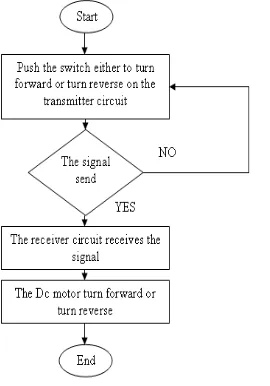
wireless camera controller system is shown in Figure 1 and Figure 2 shown the flow chart for the controller of project.
Figure1: Design and construction of project
Figure 2: Flow Chart for the Controller of Project Figure 3 shows the blocks of operation for control the position of wireless camera. The frequency will be use in this project is 315 MHz for transmit and receive. The
rotation of wireless camera will be control by the motor driver circuit.
Figure 3: Block Diagram Operation for Control the Position of Wireless Camera
III. THEORY
Wireless systems consist of combined RF components such as transmitters, receivers, transceivers, filters, down / up converters, antennas, and antenna positioners [1]. Wireless systems use low-powered radio waves to communicate data between these devices without the use of cables. Wireless systems are widely used in computer networking and communication applications. These devices communicate with each other and transmit data using wireless access protocols. Wireless communication may be via Radio Frequency Communication, Microwave Communication for image long range line of sight via highly directional antenna or short range communication and Infrared (IR) short range communication for image from remote controls.
The basic of communication system is to communicate data or information from one point called source of generation to distant point called destination of end user. The communication channel or media connects source as well as destination over telephone lines, microwave links and optical fiber cable. The basic of communication block diagram as shown in Figure 4.
Figure 5: Block Diagram for Display Image Image capturing can be done using wireless camera available in various resolutions. There are two types of cameras generally available which is digital cameras (CCD charge coupled device and CMOS sensor based) and analogue cameras. Digital cameras generally have a direct interface with computer (USB port) but analogue cameras require suitable grabbing card or TV tuner card for interfacing with computer. Power requirement of Wireless cameras give high quality and low noise images. It generates an analog signal and uses analog to digital converter (ADC) and thus consumes high power.
IV RESULTS
The main part of this project is wireless controller which is Transmitter, Receiver, DC Motor Circuit and Regulator Circuit. The transmitter is to transmit the signal from input to the receiver. The switch is use as an input to control the DC motor to turn right or turn left. In this part, have a several main component to make sure the circuit or operation fully functioning very well such as:
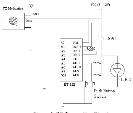
A- Encoder IC
The kind of Encoder integrated circuit use in circuit is HT-12E. The Encoder is series of CMOS LSIs for remote control system applications. They are capable of encoding information which consists of N address bits and 12-N data bits. The programmed addresses or data are transmitted together with the header bits via an RF or an infrared transmission medium upon receipt of a trigger signal. The capability to select a TE trigger on the HT-12E enhances the application flexibility of the 2^12series of encoders.
B- RF Transmitter Module (TX Modulation) RF Transmitter Modules (TX Modulation) are very small in dimension and have a wide operating voltage range from 3V to 12V. This RF transmitter can be used to transmit signal up to 100 meters. The antenna design, working environment and supply voltage will seriously impact the effective distance. data and transmit the signal to the RF receiver Module with the limited distance and to follow the accurate frequency. In the receiver also have two main parts to make this circuit number of addresses and data format should be chosen. The decoders receive serial addresses and data from a programmed of encoders that are transmitted by a carrier using an RF or a transmission medium.
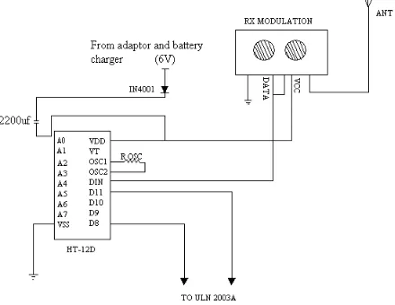
B- RF Receiver Module (RX Modulation)
Figure 7: RF Receiver Circuit
Figure 7 shows the RF Receiver Circuit. When the RX module receives the signal from transmitter, the decoders receive the data and pin DIN activates the oscillator which in turn decodes the incoming address and data. If the received address codes all match, the decoder activate the output pins. The source of this circuit use adaptor which is connects to the regulator circuit as common supply and battery charger as backup supply. The reason act of adaptor connect to the regulator circuit because the RX Modulation need VCC 6V, so the kind of this regulator is 7806 where produce the output fix 6V. Figure 8 shows the regulator circuit.
Figure 8: Regulator Circuit
Another important circuit used in this project is the Driver Motor Control Circuit to control the rotation of wireless camera. In Driver Motor Control Circuit have a several main component such as:
A-IC ULN 3002A
The ULN 2003A is a versatile devices useful for driving a wide range of loads including solenoid, relay Dc motor, LED display and other. The ULN 2003A are high voltage and high current Darlington array. Each consist seven NPN Darlington pairs that features high voltage output with common cathode clamp diode for switching inductive loads. It can accept output voltage of up 50V
B-Relay
The relay used in this circuit is 6V coil as a switching to control the dc motor either to turn forward or turn reverse. When a current through the coil, the resulting magnetic field attract an armature that is mechanically linked to a moving coil. When the current to the coil is switched off, the armature is returned by a forced approximately half a strong as the magnetic force it relaxed position. If the coil is energized with Dc motor, a diode is frequently installed across the coil
Figure 9: Driver Motor Circuit using ULN 2003A F
Fiigguurree 88 sshhoowwss tthhee ssiimmuullaattiioonn ooff ddcc mmoottoorr ccoonnttrrooll c
ciirrccuuiittuussiinnggUULLNN22000033iinnPPrrootteeuussDDeessiiggnn..TThheerreellaayyiinntthhiiss c
ciirrccuuiitt aass aa sswwiittcchhiinngg aanndd UULLNN22000033AA aassaaddrriivveerrmmoottoorr e
eiitthheerrttoottuurrnnffoorrwwaarrddoorrttuurrnnrreevveerrssee..WWhheenntthheeccooiillrreellaayy11 i
iss eenneerrggiizzeedd,, ccoonnttaacctt rreellaayy iinn nnoorrmmaallllyy ooppeenn bbeeccoommee n
noorrmmaallllyycclloosseedd..IInntthhiissccoonnddiittiioonntthheeddccmmoottoorrwwiillllbbeettuurrnn f
foorrwwaarrdd,, aasssshhoowwnn iinn FFiigguurree1100..TThheeooppeerraattiioonn ooff rreellaayy22 s
saammeessuucchh aass rreellaayy11,,ddeeppeenndd oonn iinnppuuttooffUULLNN22000033AAaass s
Figure 10: 9 DC Motor Turn Forward
Figure 11: DC Motor Turn Reverse
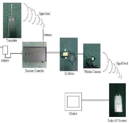
When the switch on transmitter is push either forward or reverse, the encoder IC HT-12E will encoder the signal and send that signal by the TX Modulation to the RX Modulation with carries transmission system. The RX Modulation will send the signal to decoder IC HT-12D to decode back into the original signal either the dc motor should be turn forward or turn reverse. The image will be capture and send to the Radio AV Receiver by the wireless camera and that image will display by the monitor. Figure 12 shows the overall operation of the Wireless Camera Controller using radio frequency.
Figure 12: Overall Operation of the Wireless Camera
Controller Using Radio Frequency
V CONCLUSION
This paper describes the development of the Wireless Camera Controller for Mobile Robot using Radio Frequency. The devices make process easy where the wireless camera can control by the transmitter controller which is the wireless camera able to rotate 360 degrees to observe the environment. The communication of the transmitter controller to the receiver controller will be in real time.
ACKNOWLEDGEMENTS
We wish to express our gratitude to honorable University (Universiti Teknikal Malaysia Melaka) especially to Faculty of Electrical Engineering for give the financial as well as moral support for complete this project successfully.
REFERENCES
[1] Walter A. Elmore. Protective Relaying Theory and Application. Marcel Dekker, Inc
[2] Vladimir Gurevich (2008). Electronic Devices on Discrete Components for Industrial and Power Engineering. London-New York: CRC Press, 418
[3] Anderson (1998). Wireless Cameras Operating Manual. Tommy Gamis.
[4] John Wiley & Sons (2003).Control System Engineering.4th
Edition.S. Nise Norman. [5]
http://www.alibaba.com/product-gs/51531904/Power_Window_Motor_Window Motor_Universal_Type_.html
[7] The SINTEF Group, The Foundation for Scientific and Industrial Research at the Norwegian Institute of Technology
[8] Pearson Prentice Hall (2005).Introduction To Robotics, Mechanics and Control.3rd Edition.John J. Craig