DEVELOPMENT OF AUTOMATIC WATER LEVEL CONTROL AND IT’S MONITORING SYSTEM
MOHD SYARAFI BIN MUDA
A report submitted in partial fulfillment of the requirements for the Bachelor of Electrical Engineering (Control, Instrumentation and Automation)
Faculty of Electrical Engineering
UNIVERSITI TEKNIKAL MALAYSIA MELAKA
“I hereby declared that I have read through this report entitled “Automatic Water Level Control and Its Monitoring System” and found that it has comply the partial fulfillment for awarding the degree of Bachelor of Electrical Engineering (Control, Instrumentation, and Automation)”
I hereby declared that this report entitle “Automatic Water Level Control and Its Monitoring
System” is the result of my own research except for the excerpts that have been cited clearly in
the references. The report has not been accepted for any degree and it is not concurrently
submitted in candidature of any other degree.
Signature : ………
Name : MOHD SYARAFI BIN MUDA
ACKNOWLEDGEMENTS
In the name of Allah, Most Gracious, Most Merciful who has given me strength and
patience to complete this final year project and deliver it. It will not be successful without the
contribution and perseverance support of numerous people.
First of all, I would like to express my deepest gratitude to my project supervisor
Madam Azrita binti Alias for her valuable advices, guidance and assistance. Her excellent
supervision had been the key factor for the success of the Final Year Project II (PSMII).
Indirectly, I would like to express my appreciation to all participants who had
volunteered in this study. Without their contribution, there would not have any project testing
conducted. I wish to thanks for their participation and patient throughout the testing
procedures. Thanks a lot to my friends and all BEKC members for their additional support and
encouragement that I need in my way to complete this thesis.
Finally, special tribute goes to my parent Mr. Muda Mamat and Madam Maznah Ngah
who had taught me the good things that really matter in the life and thanks for the love that
iii
ABSTRACT
Nowadays robotic and automation system has been introduced to facilitate humankind from
doing everyday chores to the high scale manufacturing. A control and automation system is
very important for country to generate economy throughput optimization and better product.
Therefore, it needs the modern and exceptional automation system. Based on that requirement,
an “Automation Water Level Control and Its Monitoring System” have been developed. The
water levels in tank automatically control by the pump. It also can monitor the system on the
personal computer PC with the interfacing system. Visual Basic software is used as software
tool to produce a graphic user interface (GUI). An electronic sensor circuit was detecting the
water level and give signal to the Programmable Logic Controller PLC. The PLC control the
pumping system to allow the amount of water that will be flow into the tank. The whole
processed will be connected by parallel port to the personal computer and monitor the water
ABSTRAK
Hampir kesemua pekerjaan dalam kehidupan manusia seharian masakini telah di permudahkan
oleh penggunaan robot dan sistem automasi. Ia meliputi kerja harian biasa sehinggalah kepada
penghasilan produk yang banyak dan berkualiti. Memandangkan sektor kawalan dan automasi
adalah amat penting untuk menjana ekonomi negara melalui produk yang lebih optimum dan
berkualiti tinggi, maka satu sistem kawalan yang moden dan cekap adalah perlu. Berdasarkan
keperluan ini, projek ” Sistem Automasi Kawalan Paras Air serta Pengawasan ” dibangunkan.
Projek ini mengawal takat air di dalam tangki simpanan secara automatik menggunakan pam.
Ia juga dipantau oleh sistem kawalan melalui paparan pada komputer. Perisian Visual Basic
digunakan bagi membina pengantaramuka grafik pengguna. Pengesan jarak mengesan takat air
dan menghantar isyarat yang diterima kepada Pengawal Logik Aturcara (Programmable Logic
Controller-PLC). PLC mengawal sistem pengepam air bagi membolehkan sejumlah air masuk
ke dalam tangki simpanan. Isyarat yang dikawal dari PLC akan dihantar ke komputer melalui
v
TABLE OF CONTENT
CHAPTER CONTENT PAGE
ACKNOWLEDGEMENT ii
ABSTRACT iii
ABSTRAK iv
TABLE OF CONTENTS v
LIST OF TABLES x
LIST OF FIGURES xi
LIST OF ABBREVIATIONS xiv
LIST OF APPENDICES xv
I INTRODUCTION
1.1 Overview 1
1.2 Objective of project 1
1.3 Scope of project 2
CHAPTER CONTENT PAGE
II LITERATURE REVIEW
2.1 Overview 3
2.2 Literature Review 4 2.2.1 Water Level Control System 4
2.2.2 Liquid Level Monitoring Systems 6 2.2.3 Application of Water Level Control System 11 2.2.3.1 Monitor Water Level in sand tank 11 2.2.3.2 Monitor Water Level in Brunei River 12 2.2.3.2 Water Pumping System 13 2.2.4 Types of Water Level 15 2.2.4.1 Float Switch 16 2.2.4.2 Ultrasonic Sensor 17 2.2.4.3 Magnetic Level Gauges 18 2.2.4.4 Capacitive Transmitter 19
2.3 Project Background 20
2.3.1 Water Level Sensor Circuit 20 2.3.1.1 Dual Water Level Sensor Circuit 20 2.3.1.2 Water Level Detector Circuit 23 2.3.2 Programmable Logic Controller 26
2.3.2.1 Parts of PLC 28
2.3.3 Two Way Valve 30
2.3.4 Pump 32
vii
CHAPTER CONTENT PAGE
III METHODOLOGY
3.1 Overview 36 3.2 Project Methodology 38
3.2.1 Research and Study 38
3.2.2 Design Water Level Sensor Circuit 38
3.2.3 Design PLC 40
3.2.3.1 CX-Programmer 41
3.2.4 Design and wiring hardware 44 3.2.4.1 Components Water Level Circuit 44 3.2.4.2 Hardware Implementation 49
3.2.5 Design Visual Basic 53
3.2.5.1 Visual Basic 6 53
3.2.5.2 Starting Visual Basic 53 3.2.5.3 Properties Window 55
3.2.5.4 Toolbox 56
3.2.6 Interfacing with Parallel Port 57
3.2.7 Analysis 59
CHAPTER CONTENT PAGE
IV RESULT AND DISCUSION
4.1 Overview 60
4.2 Hardware Implementation 60
4.2.1 Water Level Sensor Circuit 60
4.2.1.1 Circuit’s Analysis 61
4.2.1.2 Circuit Simulation 62
4.2.1.3 Simulation Result 65
4.2.1.4 Circuit Implementation 67 4.3 Software Implementation 68
4.3.1 PLC 68
4.3.1.1 I/O Assignments 68
4.3.1.2 PLC’s Analysis 71
4.3.2 Visual Basic 72
4.3.2.1 Codes Programme 72
4.3.2.1 Main Control System 74 4.3.3 Interfacing Parallel Port 78
4.4 Project Implementation 80
ix
CHAPTER CONTENT PAGE
V CONCLUSION AND RECOMMENDATION
5.1 Conclusion 84
5.2 Problem Encountered 85
5.2.1 Electronic 85
5.2.2 Mechanical 86 5.2.3 Software Programming 86
5.3 Recommendation 87
REFERENCES 88
APPENDICES 89
Appendix A 89
Appendix B 90
Appendix C 91
Appendix D 92
LIST OF TABLES
TABLE TITLE PAGE
2.1 Parts of Valve 31
4.1 Input I/O Assignment 69
4.2 Output I/O Assignment 70
4.3 Internal Relay Assignment 70
xi
LIST OF FIGURES FIGURES TITLE PAGE 2.1 LEVEL MASTER Water Level Control System 4 2.2 Monitoring System of Water Level 5
2.3 Type of Sensor 5 2.4 Water Level Sensor 6
2.5 Typical Water Supply System 7 2.6 Water Level Control System 8
2.7 Field Water Supply 8 2.8 Sump Pump 9
2.9 Automatic Water Level Control 10
2.10 Acoustic Wave Sensor 11
2.11 Water level control in Brunei River 12
2.12 Water Pumping System 13
2.13 Microcontroller Architecture 14
2.14 Example types of Water Level Sensor 15
2.15 Example of Float Switch 16
2.16 Application Float Switch 16
2.17 Example of Ultrasonic Sensor 17
2.18 Application Ultrasonic Sensor 17
2.19 Example of Magnetic Level Gauges 18
2.20 Application of Magnetic Level Gauges 18
2.21 Example of Capacitance Transmitters 19
2.22 Application of Capacitance Transmitter 19
2.23 Sensor setup 22
2.24 Illustrates the complete circuit 22
FIGURES TITLE PAGE
2.26 PLC Block Diagram 7
2.27 Example of PLC Block Diagram 28
2.28 I/O Assignments Types 29
2.29 Ladder Diagram 29
2.30 Valve Diagram 31
2.31 Pump Principle 32
2.32 Pump wiring 33
2.33 Pump Motor 33
2.34 Parallel Port 34
2.35 Parallel Port Pin 34
2.36 Wiring of Parallel port 35
3.1 Project Flowchart 37
3.2 Water Level Sensor Circuit 39
3.3 Multisim 9 Software 40
3.4 Multisim 9 Display 40
3.5 CX-Programmer 41
3.6 CX-Programmer Display 42
3.7 Chosen Type of PLC 42
3.8 PLC Flowchart 43
3.9 List of Components 45
3.10 IC-CD4066 46
3.11 Diagram of IC-CD4066 46
3.12 Electronic Level Detector 47
3.13 LED 47
3.14 Alarm Buzzer 48
3.15 Switch ON/OFF 48
3.16 Water Level Detector Circuit 49
3.17 Panel Board 49
3.18 Hardware 50
3.19 Pump 50
3.20 2-way valve 51
xiii
FIGURES TITLE PAGE 3.22 Control Panel Board 52
3.23 Water Level Detector 53
3.24 Icon Visual basic 54
3.25 Layout Visual basic 55
3.26 Form Properties 56
3.27 Toolbox 56
3.28 Parallel Port View 57
3.29 Female pin 57
3.30 Printer Port properties 58
4.1 Water Level Detector Circuit 61
4.2 Simulation Progress 63
4.3 Measure Current Value 64
4.4 Parameter Circuit 64
4.5 Simulation Result 66
4.6 Electronic Water Level Circuit 67
4.7 Panel Box of Electronic Circuit 68
4.8 Isolating Transformer 68
4.9 Mnemonic Code Diagram 70
4.10 PLC Ladder Diagram 71
4.11 Modules Codes of Parallel Port 73
4.12 Visual basic Module 74
4.13 Codes of Programming 78
4.14 Main display of Monitoring 78
4.15 Interfacing Circuit 79
4.16 Parallel Port Circuit 79
4.17 Parallel Port 80
4.18 Main Hardware 81
4.19 Main Control Panel 81
4.20 Parts of Water Detector 82
LIST OF ABBREVIATIONS
PLC - Programmable Logic Controller
VB - Visual Basic
PC - Personal Computer
RAM - Random Access Memory
I/O - Input/Output
AC - Alternate Current
DC - Direct Current
IC - Integrated Circuit
LED - Light Emitting Diode
GUI - Graphical User Interface
xv
LIST OF APPENDICIES
APPENDIX TITLE PAGE
A Simulation Result of Water Level Circuit
B PLC Ladder Diagram
C Mnemonics List (Ladder Diagram)
D Visual Basic Codes Programming
CHAPTER 1
INTRODUCTION
1.1 Overview
Control engineering is among the most theoretical and difficult to understand. The utilizing of control and automation systems is very important in optimization production, quality and productivity furthermore reduces cost. In industries, application of water level control system is widely use especially in chemical industries. This project is about design and develops of an automatic water level control system and its monitoring system. In this project, the system uses an electronic sensor circuit to detect the water level in a tank. It will be use a Programmable Logic Controller (PLC) to control the pump for automatic incoming and outgoing of water. The monitoring system using Visual Basic software programming will be interface by parallel port between hardware and Personal Computer (PC).
1.2 Objective of Project
2
1.3 Scope of Project
The scope of this project is to develop user friendly integrated system for water level control purpose. The automatic water level control and its monitoring system will help to overview the overall process of water level control. It has a sensor that will be detect the water level, and it will generate a signal to control by the PLC. The PLC will be control the motor pump to allow the amount of water that will be flow into the tank. When the water is reaches at a high level the sensor will be sent a signal to PLC to stop the pump. The overall system will be monitor from the personal computer PC using Visual Basic software programming. Then the interfacing system using the parallel port will display the water level on the tank.
1.4 Problem Statement
CHAPTER 2
LITERATURE REVIEW AND PROJECT BACKGROUND
2.1 Overview
This chapter will be stressed on the literature review and project background of water level control system. The main purpose of this chapter is to analyze, identify and make conclusion based on the research. A literature review means a collecting related data, analyzed business process, identify underlying patterns and create the conclusion (Strauss & Corbin 1990). Another description of the project background is a systematic, explicit and reproducible method to identifying, evaluating and synthesizing the existing body of completed and recorded work produced by researcher, scholars and practitioners (Fink, 2005).
4 2.2 Literature Review
2.2.1 Water Level Control System
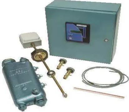
[image:21.612.225.432.246.427.2]The Level Master of water level control system had been designed byMilwaukee, WI in January 2006 for fire tube boiler and water tube boiler which is constructed with enhanced safety diagnostic capabilities.
Figure 2.1: LEVEL MASTER Water Level Control System
Figure 2.2: Monitoring System of Water Level
The water column chambers have been engineered to easily replace limited, single purpose controls with state-of-the-art electronic level sensing and monitoring. Figure 2.2 shows the monitoring system which is display the percentages for output value of water level and display user configurable for on-off or modulating water level control. The design also makes the system adaptable to both new and existing boilers. The specially engineered design of the Level Master was built to accommodate your boiler room specifications. Depending on your boiler application, the control’s sensitivity may be selected in the field.
[image:22.612.253.376.490.664.2]
6 In figure 2.3, this type of sensor employs the magnetostrictive principle, a non-contact, non-wearing, long-life technology. Designed specifically for boiler applications, it will withstand working temperatures to 400°F at 250 PSIG. It includes a 2” diameter titanium float with a captive magnet. The sensor electronics enclosure meets NEMA 4 standards with a working environment of 130°F.
2.2.2 Liquid Level Monitoring and Automatic Control Systems.
Active Control Systems have become very popular with consultants, designing Water Supply and Disposal Schemes in Industry. The main reason is that unlike normal conductivity types, these are unaffected by water corrosion. This has helped reduce the constant manual checking, and bring aboutextremely high Functional Reliability. Most of the clients are from professional maintenance/ project engineers and consultants. For the example, Oberoi Group of Hotels is consistently using the systems, both in Projects and Maintenance. So is the case with Le Meridien, Delhi, Mother Dairy, CDIL etc. This company is specializing in Liquid Level Monitoring and Automatic Control Systems which are based on Magnetic Level sensing.
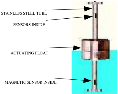
STAINLESS STEEL TUBE
SENSORS INSIDE
ACTUATING FLOAT
[image:23.612.133.338.457.621.2]MAGNETIC SENSOR INSIDE
The level sensing is done by means of a probe unit as shown in figure 2.4. It is made of stainless Steel. A number of sensors suitably spaced, depending of functional requirements are enclosed inside the Probe Unit. An Actuating Float, made from Stainless Steel or PP is used to actuate these sensors.
This Float has a Ring Magnet of specific polarity for correct operation of the Control System. The control unit will receives signal from sensors as liquid reaches their level. This signal then operates the Controller or Indicator System. The Control Systems are designed as ‘stand alone’ units and are specific to the capacity and system of operation of Pumps.
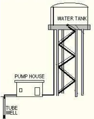
[image:24.612.237.399.367.572.2]Otherwise, type of Pumps or Valves which is can be used is any type or capacity for the example single phase mono-block pumps, jet pumps, single or three phase submersible pumps, or other heavy capacity pumps or pumps related to chemical or process or dozing etc.
Figure 2.5: Typical Water Supply System