ISSN: 1693-6930
accredited by DGHE (DIKTI), Decree No: 51/Dikti/Kep/2010 171
The Damage of Z
nO Arrester Block Due To Multiple
Impulse Currents
Tarcicius Haryono*1, K. Tunggul Sirait2, Tumiran3, Hamzah Berahim4 1, 3,4
Electrical Engineering and Information Technology Department, Universitas Gadjah Mada (UGM) Grafica St, Yogyakarta, Indonesia, Phone +62811250611
2
School of Electrical Engineering and Infomatics, Bandung Institute of Technology (ITB) e-mail : [email protected]*1, [email protected], [email protected]
Abstrak
Arester yang dipasang di sebuah sistem tenaga listrik, dimaksudkan untuk melindungi peralatan listrik dari kerusakan akibat sambaran petir. Akan tetapi, kalau yang menerpa arester adalah gelombang impuls petir yang yang berganda dengan nilai puncak arus yang tinggi, maka arester dikhawatirkan akan mengalami kerusakan dan tidak dapat beroperasi lagi sebagaimana mestinya. Dalam penelitian ini, tiga nilai puncak arus impuls, yaitu: 600, 1300, dan 2500A, yang masing-masing dengan arus impuls berganda sebanyak 5 kali, diujikan pada blok ZnO dengan rating arus 5000A (1 p.u). Blok ZnO ini merupakan 1 dari 7 buah blok ZnO yang dipunyai oleh sebuah sistem arester 20 kV. Hasilnya menunjukkan bahwa dengan nilai puncak arus impuls 600(0.12), 1300(0.26), dan 2500(0.5) A(p.u.), sampel blok ZnO yang diuji menjadi rusak sebanyak 26.58, 50 dan 100% berturut-turut dari cacah sampel yang dikenai oleh arus-arus impuls tersebut. Tambahan lagi, tegangan residu blok ZnO yang rusak menjadi bernilai kecil. Penurunan tegangan residu lebih dari 5% tegangan residu blok ZnO ketika masih baru mempunyai sifat permanen. Blok ZnO semacam ini kalau masih tetap dipasang di sistem arester pada sistem tenaga listrik akan mungkin menyebabkan pemutus beban membuka sehingga pasokan tenaga listrik untuk banyak konsumen akan terputus.
Kata kunci: arus impuls berganda, pembangkit impuls arus, shunt arus, tegangan residu
Abstract
A lightning arrester installed in an electrical power system is designed to protect some electrical equipment against damage due to lightning impulse strike. However, if there is a multiple impulse current striking a lightning arrester, it may damage the lightning arrester itself and then, as a result, it cannot provide lightning protection to the electrical equipment anymore. In this research, three peak values of lightning impulse current,which were 600, 1300, and 2500A, each of which had 5 repetitive impulse current, was applied to a 5000A (1p.u.) ZnO block of a 24kV nominal voltage lightning arrester having seven ZnO block units. The results of research showed that by applying impulse current of the order of 600(0.12), 1300(0.26), dan 2500(0.5) A(p.u.), making the ZnO block damage as much as 26.58, 50, and 100% concecutively. In addition, the damage of the ZnO block appeared as permanen low value of residual voltage as low as more than 5% of the new ZnO block residual voltage. If the ZnO block is still being used in a lightning arrester in electrical power system, it may result in the opening of a circuit breaker and possibly making electrical power outages from a number of electrical power customers.
Key words: current shunt, impuls current generator, multiple impuls current, residual voltage
1. Introduction
The use of ZnO lightning arrester now-a-days has been quickly worldwidely spread. Compared to previous kind lightning arrester, which uses SiC (silicon carbide), the ZnO arrester has better characteristics. The advantages of ZnO arrester against SiC arrester are it provides good protection characteristics, high reliability, better performance for low impedance network (in the case of the use of cable and capacitors), and high energy absorption capability [1]. One disadvantage of the use of SiC arrester is that it produces follow currents, whlich flows after a lightning signal being disappeared. This condition is possible to make an electrical power toward an outage condition.
more than one stroke, typically having 3 up to 4 strokes [3] with the difference time between two concecutive strokes are 20 up to 200 miliseconds.
According to Darveniza[4], lightning arrresters that are used in electrical power distribution protection against lightning strikes experience lightning strike stresses. Therefore, the arrester performance in the lightning strike condition is a critical issues. The finding of his investigation revealed that repetitive or multiple lightning strikes resulted in more severe damage to lightning arrester as compared to the implementation of standar lightning current test. Futher, Darveniza found that multiple pulse current affected the performance of a lightning arrester. By the implementation of 6 concecutive 5 kA impulse currents with 35 mS duration time between a concecutive impulses, it was found that the lightning arrester experienced accumulative damage.
IEC standard [5] gives the guidance in testing lightning arrester by applying 4 group impulse currents, each of which consisting of 5 impulse currents of 8/20 µs waveshape with time difference berween 2 concecutive impulses being 1 minute and time difference between concecutive group being 30 minutes.
Miyaki [6] reported that eventhough a ZnO lightning arrrester shows good performance in electrical equipment protection against lightning, by considering that the ZnO lightning arrester may degrade in it’s operation, an air gap is put in series to it. This is to prevent from electricity supply failure whenever the ZnO lightning arrester has been degraded. To study futher, Miyaki carried out an investigation by making the combination of the application of impulse voltage and impulse current. It was found an impulse current treshold, above which the failure of the ZnO lightning arrester block happened. The treshold of the impulse current was 60 kA for 5000 A rating of ZnO block. The failure mainly appeared as striped-shaped destruction in the outer surface of a ZnO block. Flashover happened at that part of the ZnO lightning arrester block.
Bok-Hee Lee [7] wrote the research in studying the effect of multiple impulse voltages on the electrical and physical properties of a zinc oxide (ZnO) varistor. The multiple combination wave generator is able to produce quintuple 1.2/50 µS impulse voltages of 100 kV and quintuple 8/20 µS impulse current of 12 kA. By applying these impulse voltages and currents, the electrical and physical properties of the ZnO varistor were evaluated.
In this research, impulse current generator was constructed having very low inductance value by making coaxial based construction. By having a very low inductance value, the possibility of having oscillation on the multiple impulse signal produced is reduced. The number of impulse currents produced is 5 having 35 mS time difference between two concecutive impulses. This is accordance with the lightning strike, especially time difference between strokes, that happen in Indonesia according to Zoro [2] and the number of stroke is in accordance with IEC standard [5]. The difference to above researches[4, 6, 7] was that in this research, it was intended to study the effect of the application of peak values of multiple impulse current, that is lower than the current rating of the ZnO lightning arrester. In this case, the peak values of the multiple impulse current applied to ZnO arrester block were 600 A, 1300 A, and 2500 A , which were lower than 5000 A ZnO block current rating. Then, the ZnO block performances carried out were : ZnO accumulating energy, the possibility of ZnO damage when the peak of impulse current increased, the ZnO impedance before and after the implementation of the multiple impulse current to ZnO block, the ZnO residual voltage, and possible disadvantages to electricity supply service and possible damage to telecomunication, computing, control, and other electronic equipments. The ZnO blocks were investigated futher by the use of FTIR (Fourier Transform Infra Red) or infra red spectroscope and X ray diffractometer to explore the information related to the damage of ZnO arrester blocks.
2. Research Method
2.1 Object to be Investigated
current rating. Sometime two or three columns of ZnO blocks are connected in paralel to increase the current rating of the lightning arrester.
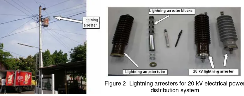
In this study, four out of seven ZnO blocks, belonged to a 20 kV ZnO lightning arrester, appeared in Figure 2. The 20 kV ZnO lightning arrester under investigation has a nominal voltage of 24 kV and current rating of 5000 A. Inside the 20 kV ZnO lightning arrester tube, there are 7 ZnO blocks. Therefore, a ZnO block has a nominal voltage value of 24 kV/ 7 = 3,428 kV = 3428 volt = 1 p.u. The assumption taken for this study is that if a lightning impulse current flowing through the lightning arrester, there is a nearly linear voltage distribution along the column of the 7 ZnO blocks connected in series in side the arrester tube. It means that the voltage value across every ZnO block is nearly the same. This is supported by the research done by Kojima [12]. Therefore, to study the lightning strike effect to ZnO lightning arrester can be based upon the study of one ZnO block. One advantage obtained is that the research can be conducted using reduced source voltage value. When it is needed to calculate the voltage for a real lightning arrester, it is a matter of multiplying the voltage across one ZnO block obtained by a proper factor. When it is the real impulse current flowing through the lightning arrester that is wanted to be calculated, it can be done similarly by applying another multiplication factor to the the value of current obtained.
Figure 1. Lightning arrester at 20 kV electrical power distribution system
Figure 2 Lightning arresters for 20 kV electrical power distribution system
2.2 Multiple/Repetitive Impulse Current Generator.
An impulse current generator that is able to produce impulse current waveshape of 8/20 µs was successfully made, Figure 3. In this figure it can be seen that there is only one high voltage capacitor, but actually there are 5 high voltage capacitors, each of which has the capacitance value of 34 µF and the maximum charging voltage allowed is 25 kV. Each capacitor, after they have been charged using DC current charge, can be individually triggered at different times producing an impulse current intended to flow through a ZnO blocks of a lightning arrester to be tested. The impulse current peak value can be produced up to 15 kA. In addition, the difference in time between concecutive impulse current can be set at the value of time up to 1000 ms using computerised impulse current trigger circuit. In this research the time difference between one impulse current and other was to be 35 ms, see Figure 4.
By applying different direct voltage of 10 kV, 11 kV, and 13 kV charging the capacitors, impulse currents of 600 A, 1300 A, and 2500 A can be produced concecutively. In this research, the peak values of impulse current of 600 A, 1300 A, and 2500 A were used to carry out the investigation
Figure 3. Impulse current generator circuit
Figure 4. Multiple impulse current 8/20 µs waveshape
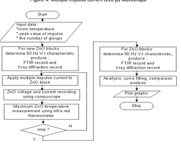
Figure 5. Flowchart of the research conducted
C
RC
ZnO
Current shunt
Voltage Devider 1
220 volt
Transformator 220/13200 Volt
Grounding
Brass rod
Bras plate
R = 210 kohm Diode
shield
Volta -ge devid er 2
2.3 Steps to Conduct Research
In order to well conduct the research, a flowchart shown in Figure 5 was made. It can be seen that the determination of 50 Hz V-I characteristic of ZnO block is done before and after the application of the multiple impulse current to the ZnO blocks. By comparing both characteristics, it can be analysed if there is some change in the ZnO block material. Futher, in order to be able to differentiate between the condition before and after the application of the multiple impulse current to the ZnO blocks and to add some important information, two kinds of recording system, in addition, were apllied to ZnO blocks : by the use of FTIR (Fourier Transform Infra Red) or infra red spectroscope, and X ray diffractometer.
Analisis of data obtained were done by means of computer application programs such as SPSS, Matlab, and Excel.
3. Results and Discussion
3.1 The ZnO Block Response to Multiple Impulse Currents
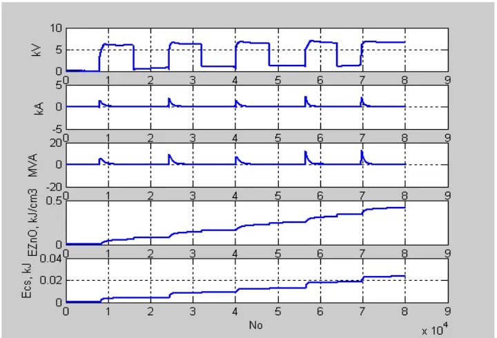
Five concecutive impulse currents having the peak impulse current of 2500 A was impinged on ZnO blocks. The compuscope seen in Figure 3 recorded the voltages of currentshunt, and the voltages of series connection between current shunt and the ZnO block. Then the recorded data were analysed using Matlab computer program to give the information as shown in Figure 6 from the top to bottom curves as followed : the first curve is ZnO residual voltage, the second curve is impulse current, the third curve is MVA ZnO, the fourth curve is energy density of ZnO, and the fifth curve is currentshunt energy. When the first impulse current increases, the voltage of ZnO raises, but it is limited to ZnO’s residual voltage value, which is nearly constant at the residual voltage value of 7052,9 volt. This is the protective level of the ZnO block for equipment. As the impulse current decreases to zero value, the residual voltage of the ZnO is not reduced to zero but has a small value. At the time when the second impulse current up to the fifth impulse current strikes the ZnO block, the similar values of residual voltage are recorded
The energy absorbed by ZnO block, however, see the 4th curve in Figure 6, accumulates from the 1st impulse current up to the 5th impulse current. The assumption used in this research is that there was no energy loss from the ZnO block to the air surrounding it due to the small duration of time between impulse, which was only 35 ms. This is supported by Darveniza[1993] statement that for impulse duration of less than 1 second heat loss can be neglected.
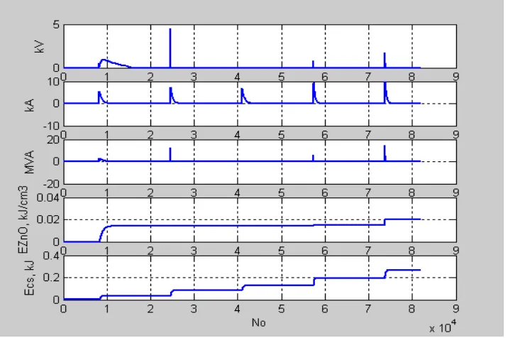
Figure 7 The response of ZnO sample A2.5K30.2.2
Futher, it can be noticed that when the impulse current is zero, the energy of the ZnO block doesnot change. This is logical because during that time, the energy of the ZnO block:
E=
∫
vidt
=
0
, if i = 0 there is no energy value added to the energy obtained before.However, the residual voltage is not appeared as wide waveshape as the one before when the following group of impulse currents impinged on the ZnO block, Figure 7, instead there are seen as very narrow impulse voltages followed by zero voltage value. This is an indication that the ZnO block has been damaged.
3.2 The ZnO Block Damage due to Multiple Impulse Current
In order to know the effect of having higher values of the peak of impulse currents to ZnO blocks, an investigation was conducted dealing with three different peak values of impulse current, that were 600 A (0,12 p.u), 1300 A (0,26 p.u), and 2500 A (0,5 p.u). The basis p.u. value was taken from the ZnO lightning arrester current rating, which is 5000 A. Then 1p.u of impulse current = 5000 A. This reseach was done by using the same number of ZnO block units, which were 14 units, for each peak value of impulse current. The number of ZnO block damaged can be seen in Table 1. The higher the impulse current values applied, the more percentage of the ZnO block damage.
Table 1. Damage samples of ZnO block due to impulse current at 30°C
Impulse Impulse The Number of The Damage
current current ZnO Blocks Of ZnO Block
A p.u. %
600 0.12 14 28.57
1300 0.26 14 50
2500 0.5 14 100
Note : the rating current of the ZnO arrester = 5000 A = 1 p.u.
the ZnO block. When the temperature was futher raised higher than upper thermal stability limit of the ZnO block, the ZnO block damage results were obtained. In this case the damage of the ZnO block were in the form of low impedance of the ZnO blocks.
3.3 The Effect of the Application of Multiple of Impulse Current to 50 Hz ZnO block Impedance
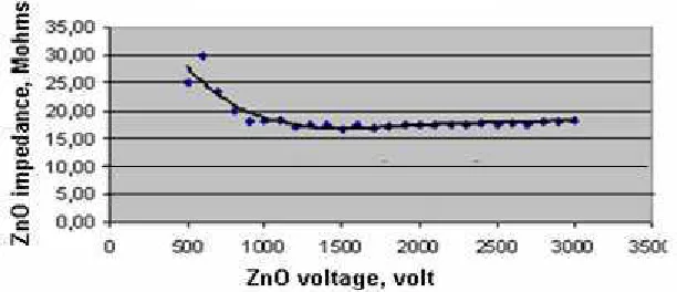
Before and after a ZnO block being stroken by multiple impulse currents, 50 Hz alternating current was flown through it at 3000 volt (= 0.88 p.u, with 1 p.u. = 3428 volt, the rating of a ZnO arrester having 7 ZnO blocks = 24 kV. Then the nominal voltage of one ZnO block = 24 kV/7 = 3428 volt = 1 p.u.). Both value of currents can then be compared in order to provide some information related to the results. For 600 A peak value of impulse current, the ZnO block did not experience any damage, see Figure 8. In this case, the multiple impulse current flowing through the ZnO block was too small to make some change in it’s intergranular material locating in the area between the ZnO block crystals.
When the peak value of the multiple impulse current was increased to 2500 A and it stroke the ZnO block, the ZnO block became damage. This is seen as the diference in it’s 50 Hz impedance characteristic of the ZnO block, see Figure 8 and Table 2.
When a ZnO block had been damaged by a multiple impulse current, in the frequency of 50 Hz, there was an increase in leakage current by about 1000 times from 0.12 mA increasing to 100 mA or in term of impedance, the ZnO impedance shaply decreased, from 16 Mohms to 0.002 Mohms. The change in the value of current flowing through the ZnO block is due to the change in the physical properties resulting in it’s electrical properties of intergranular materials located between ZnO crystals. This is supported by Fujiwara[11] mentioning that the intergranular region is the part where the strong nonlinear V-I characteristic originates. Therefore, the electric characteristic of the element is very sensitive to the additives, their composition and sintering process. In adition, it is mentioned that the ZnO grain has only low value of resistance. Before the ZnO block is damage, the intergranular material provides non linear impedance characteristic of the ZnO block. It means that at low value of voltage, the ZnO impedance is high while at high voltage value, the ZnO impedance is low. After the ZnO block damage, the non linear characteristic of the ZnO block is not able to return back to its original value anymore. In this condition, the impedance is greatly decreased, see Figure 9. The tree curves at lower part of this figure represented the characteristic of the damaged ZnO blocks. Therefore, the damaged ZnO blocks cannot be used as electrical equipment lightning protection means anymore.
Figure 8 The impedance of ZnO block before and after the Implementation of multiple impulse current strike
Tabel 2 The 50 Hz and 3000 Volt current and impedance of new and damaged ZnO block
New ZnO block Damage ZnO block
Current (mA) Impedance (Mohm) Current (mA) Impedance (Mohm)
Figure 9 The change in ZnO impedance due to ZnO block damage
3.4 Residual Voltage of ZnO
When each multiple impulse current having various peak values of 600 A = 0.12 p.u, 1300 A = 0.26 p.u., and 2500 A = 0.5 p.u., was individually flown through a ZnO block, the voltage across the ZnO block, which was called ZnO residual voltage, can be measured. When the ZnO block was still good, the residual voltage recorded was lower than BIL of equipment insulation. The data obtained from investigation, which was shown in Figure 10, revealed that good ZnO block provided good residual voltage, which was about 1.8 p.u. However, data inside the square line showed that the higher the maximum value of ZnO impulse currents resulted in more decrease in the value of ZnO residual voltages. Mathematical regression formulas was made using the order of 5 with coeficient of determination of R2 = 0.2869. This smaller value of the coeficient of determination indicates that the experiment data obtained were so widely scattered. Eventhough the data obtained are widely scattered, at least, it shows the trend of the ZnO block residual voltage in conjunction to the maximum of impulse current values.
Figure 10 Damage ZnO causing the decrease in ZnO residual voltage
Voltage 1 p.u. = 3428 volt,
Maximum of impulse current 1 p.u. = 5000 A
When another impulse current impinged on a damaged ZnO block, the residual voltage was decreased toward a value of
Vres
=
0
volt.blocks damaged.The second condition is that the ZnO lightning arrester was damaged due to ZnO lightning arrester block being open circuit. The third condition is that the damaged ZnO lightning arrester block is in the form of short circuit [10]
When a ZnO lightning arrester block was stroken by a multiple impulse current having a peak value of impulse current of 1300 A under room temperature of 30°C, the ZnO lightning arrester block was broken into pieces, see upper left part of Figure 11 (a), at the application of the fourth impulse current. This condition is very rare to happen. Please compare the broken one with the good one on lower right part of Fig 11 (a).
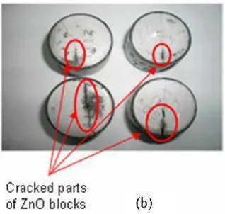
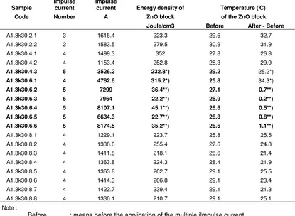
Multiple impulse currents applied to ZnO lightning arrester blocks that resulted in it’s failures oftenly found in the form of ZnO block cracks, see Figure 11 (b). This was caused by the fact that the impulse energy given to the ZnO block produced unhomogen thermal stress to the ZnO arrester blocks. This thermal stresses was caused by non uniform temperature distribution [8] in the ZnO block. If the thermal stresses is higher than failure stress of the material, it can lead to cracking. That was why, when the next impulse strikes the ZnO block, the flashover happened through the cracked part path (the open part having air content). As the result, there was no addition energy absorbed by ZnO block and the difference in temperature measured before and after the application of multiple impulse current was very small, which was less than 1,1°C while it was in the range of 21,2°C up to 31,9°C for good ZnO block at 1300 A peak value of impulse current, see Table 3.
Figure 11. ZnO block damages:
(a) ZnO block broken into pieces and new ZnO block (b) ZnO block craked parts (short circuit)
It is clear from Table 3 that the bolded sample codes give the information that the ZnO samples have been damaged, while unbolded ones infom that the ZnO sample are still good. The largest impulse current flowed through the good ZnO block was only 1615.4 A belonged to sample having the code of A1.3k30.2.1, while the impulse current flowed through the ZnO blocks making the ZnO block damaged due to the current value of 2 up to 5 times as much.
The good ZnO block energy densities have a range of 202.7 up to 352 joule/cm3, see data in Table 3 in column 4 at unbolded data, while the energy densities of damaged ZnO blocks making low temperature rise, which are having the range of 0.2 (belonged to sample with sample code of A1.3k30.6.3) up to 1,1 ( belonged to sample with sample code of A1.3k30.6.6) Joule/cm3
resulted in the low energy density of ZnO block, which was 36.4 Joule/cm3 and low raise in ZnO temperature, which was 0.7°C. This condition can be explained as follows. Because the ZnO block had been cracked by the previous application group of multiple impulse current (sample code A1.3k30.6.1), so the application of the next multiple current produced the flow of impulse current being not through the ZnO material, but through the cracked part one, it means through the air within the crack. Therefore the energy density of the ZnO was low and also the ZnO temperature after the application of the multiple impulse current was low too.
Table 3 Energy density and temperature of good and damage ZnO blocks when stroken by 1300 A multiple impulse currents at 30°C room temperature
Sample
After - Before : temperature rise or the different in temperature values after and before the application of multiple impulse current
*) the conditions related to the ZnO block craked started to happen **) the conditions after the ZnO block craked has been created
Different condition was experienced by the sample code of A1.3k30.4.3, see Table 3. This condition indicated that the sample started to be damaged. The indication is that the maximum energy density allowed to create the damage to ZnO block was 232.8 Joule/cm3. The temperature rise was still high 25.2°C. Certainly, the impulse current still flowed through the ZnO material. The result was that the ZnO crack created. If the next group impulse current was flown, then most of impulse curent would flow through the cracked part, the energy density of ZnO block, as the result, would be low, and so the ZnO block temperature rise. However this condition never happened due to no sample code of A1.3k30.4.4 in Table 3, in other words, the experiment was not to be continued for the next group of multiple of impuls current.
3.6 Infra Red Spectroscope and X ray Spectroscope
An electromagnetixc radiation: X ray has photon energy in the range of 100 eV – 100 keV. An Xray difractometer is an instrument for studying diffraction of X rays, that impinged on material for determination of it’s atomic and molecule structure because the energy of X ray enables to enter some material and gives the material structure information [9]
Figure 12. Infra red spectroscope of new and undamage ZnO blocks
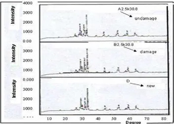
Figure 13 X ray spectroscope of new, damage and undamage ZnO blocks
infra red spectroscope as shown in Figure 12 and to X ray producing Xray spectroscope. Figure 13.
For 5 ZnO samples : A, B, A0.6k30.2, A0.6k30.8, and A1.3k30.8, see Figure 12. it is clear that the five samples experience peaks transmittances followed by sharp drops (largest absorbance of the infra red) at nearly the same value of frequencies. This indicates that there is no change in the ZnO chemical compounds for new and undamage ZnO block. Even the damage ZnO blocks one also experiences the same respond to the infra red exposure.
The results of the exposure of X ray to ZnO block, Figure 13, indicate that new ZnO block (sample D) damage one (B2.5k30.8 sample) and undamage one (A2.5k30.8 sample) have the same spectroscope shapes. It can be concluded that there is no change in chemical compound of ZnO material. The different in impedance between good and damaged ZnO block, see Figure 9, was not caused by difference in their chemical compounds but difference in their physical structure of material.
4. Conclusion
Small peak current value, which is smaller than the ZnO lightning arrester current rating, applying to ZnO lightning arrester results in possible damage to a ZnO lightning arrester due to it’smultiple impulse current waveshape. Higher the peak impulse current value produces higher percentage of ZnO lightning arrester damage.
Most of ZnO block failures are in the form of the ZnO block cracks shown by low energy densities received by the ZnO blocks and as a consequence makes smaller temperature rise of the ZnO block. This kind of failure results in big leakage current flowing through the ZnO block as it has only low value of impedance. Next this current may be treated as ground fault current by a circuit breaker in charge.
Onother kind of ZnO block failure due to multiple impulse current application was initiated by the ZnO block explosion and then it was broken into several small pieces making it opened circuit. It means that there is no ZnO lightning arrester found as the lightning protection of electrical equipment anymore.This may endanger some electrical equipment connected, because it may experience over voltage condition that may make them damage if there is a lightning strike occuring.
References
[1] Short TA, Burke JJ, Mancao RT. Application of MOV’s in the Distribution Environment. IEEE Transactions on Power Delivery. 1994; l.9(1): 293-305.
[2] Zoro R. Insulation Coordination and Overvoltages due to Lightning Strike to Electricl Power System.
The 3rd National Conference on Electrical Power Technique. 1993; 603.1-1-20
[3] Haddath H, Warne D. Advances in High Voltage Engineering. IEE Power and Energy Series 40. the Insitution of Electrical Engineering. Bormin, Cornwall: MP Books Limited. 2004: 229.
[4] Darveniza M, Mercer DR. Laboratories Studies of the Effects of Multipulse Lightning Currents on Distribution Surge Arrester. IEEE Transactions on Power Delivery. 1993; l.8(3): 1035-1044.
[5] IEC 99-4. International Standard. Surge Arresters. Part 4: Metal Oxide Surge Arresters without Gaps for A.C. Systems. Geneva. 1991: 69.
[6] Miyaki S, Sakoda T, Otsubo M, Miyake T, Nakata N, and Knoshita F. Characteristics of Deteriorated ZnO Elements with Striped-Shaped Destruction Trace. 15th Asian Conference on Electrical Discharge. X’ian. China. 2010: A14.
[7] Bok-Hee L, Sun-Man K. Properties of ZnO Varistor Blocks Under Multiple Lightning Impulse Voltage.
Science Directs. 2006: 845-851.
[8] Sakyo H, Yoji Y, Hideaki N. Effect of local Electrical Properties on the Electrostatic Discharge Withstand Capability of Multilayered Chip ZnO Varistors. Journal of Applied Physics. July 2008; 104(1): 013701-013712.
[9] Pramanick A, Jones J. Measurement of Structural Changes in Tetragonal PZT Ceramics under Static and Cyclic Electric Fields Using a Laboratory X-ray Diffractometer. IEEE Transactions onUltrasonics, Ferroelectrics and Frequency Control. Aug2009; 56(8): 1546-1554.
[10] Munukutla K, Vittal V, Heydt GT, Chipman D, Keel B. A Practical Evaluation of Surge Arrester Placement for Transmission Line Lightning Protection. IEEE Transactions on Power Delivery. July 2010; 25(3): 1742-1748.
[11] Fujiwara Y, Shibuya Y, Imataki M, Nitta T. Evaluation of Surge Degradation of Metal Oxide Surge Arrester. IEEE Transaction on Power Apparatus and System. 1982; PAS-101 (4): 978-985.