DOI: 10.12928/TELKOMNIKA.v14i3.4055 800
Temperature Control of the 25kW Parabolic
Dish-Stirling Engine System
Liaw Geok Pheng1, Mohd Ruddin Ab Ghani*2, Chin Kim Gan3, Tole Sutikno4
1,2,3
Faculty of Electrical Enginering, Universiti Teknikal Malaysia Melaka (UTeM), 76100, Durian Tunggal, Melaka, Malaysia.
4
Department of Electrical Engineering, Faculty of Industrial Technology, Universitas Ahmad Dahlan (UAD), Jln Prof. Dr. Soepomo, Janturan, Yogyakarta 55164, Indonesia
*Corresponding author, email: [email protected]
Abstract
Nowadays, even though many researchers continue to investigate and study about Parabolic Dish based on Concentration Solar Power (CSP), the findings are not conclusive and do not provide accurate evidence and proof on the potential of CSP development in Malaysia. The missing link in the Parabolic Dish (PD) Stirling Engine system modelled is the control systems, which vary the amount of working gas in the Stirling engine. The temperature of the heater in PD system which has been modelled is overheated and causes damage to the heater material, low output efficiency, high thermal losses and effect to the lifespan of the PD system. Therefore, the primary aim of this paper was to design a control system to maximize output efficiency during a normal operation by maintaining the heater/absorber temperature at the highest safe operating point and preventing excessive range of threshold to prevent damage to the heater material.
Keywords: concentrating solar power (CSP), parabolic dish stirling engine system, control systems, heater, highest safe operating point
Copyright © 2016 Universitas Ahmad Dahlan. All rights reserved.
1. Introduction
Concentrating Solar Power (CSP) represents a powerful, clean, endless and reliable source of energy. CSP is a promising technology for power generation where the solar radiation is concentrated to generate high temperature for producing steam in a solar thermal power plant. The CSP plant is mostly established in a country with Direct Normal Irradiance (DNI) higher than 1800 kWh/m2/yr. Malaysia has the DNI of around 1500 - 1600 kWh/m2/yr, annual average daily solar irradiations magnitude around 4.21–5.56 kWhm2 and the sunshine duration is more than 2,200 hours per year [1].
However, there is no systematic study on this issue. In Malaysia, power generation from solar energy is monopolized by Photovoltaic (PV). Among available technologies for energy production from solar source, CSP could give a significant contribution to develop more sustainable energy system. CSP is a promising technology for power generation in which the solar radiation is concentrated to generate high temperature for producing steam in a CSP plant. Important features of CSP than PV are their capacity for bulk power generation and their viability in a wide range of plant sizes from a few kilowatts to several hundreds of megawatts [2]. PV and CSP solar projects face the public concerns on the land requirements for the development of CSP Plant. The land area requirements for centralized PV and CSP plants raise concerns about visual impacts. There are four types of CSP technologies which are parabolic troughs, linear Fresnel, parabolic dish and power tower. This research focused on Parabolic Dish (PD) system because it is suitable for small scale plant and it is modular, suitable for small area with each unit typically generating output of 3-25 kW. In addition, the area of the CSP plant especially the Parabolic Dish plant is smaller than the area of the PV plant [3].
dish in Malaysia environment [8].
This project is in line with the Malaysia National Renewable Energy Policy in which by 2020, solar power is expected to contribute to a minimum of 220 megawatts. To achieve this target, the nation needs to increase its power capacity, develop needed regulatory framework, business models and strengthen knowledge and skills. This research could give a big impact not only for Malaysia but for others who want to understand and analyze CSP technology [9].
2. Problem Statement
Renewable Energy Act 2011, the focus on solar energy is mainly on the solar Photovoltaic, whereby the solar themal, such as the Parabolic Dish Concentrating Solar Power (CSP) was not given enough attention [10]. This could due to the lack of thorough investigation of implementing solar CSP in Malaysia environment [11]. Nowadays, even though many researcher continous to investigate and study about Parabolic Dish based on Concentration Solar Power (CSP), but the finding of the research does not conclude and provide accurate evident and prove that the potential of CSP development in Malaysia. However, the missing link in the Parabolic Dish Stirling Engine system has been modelled and studied is the temperature control systems, which vary the amount of working gas in the Stirling engine. The temperature of the heater in PD system modelled by previous researcher is overheating and will causes damage to the heater material, low output efficiency, high thermal losses and effect the lifetime of the PD system [12]. Therefore, the primarily aim of this research is to design of the control system to maximize output efficiency during normal operation by maintaining the heater temperature in the Stirling engine at the highest safe operating point and prevent exceed the range of threshold to prevent damage to the heater material and also to carry out the fundamental investigation on the of solar CSP, focusing on Parabolic Dish type in the Malaysia environment.
3. Research Method
This chapter presents the methodology of this research. The methodology focuses on how to design temperature control system in order to maintain heater temperature within a safe operating region and retain the temperature as high as possible to maximize the output efficiency of the PD system. Figure 1 illustrates the flow chart of the research.
3.1. Temperature Control Design of 25kW PD System
Temperature control is critical because it ensures an efficient and a secure operation of the PD system [13]. The temperature of the receiver/heater should be maintained as high as possible to maximize the output efficiency of the PD system, while it must not exceed the thermal limit of the materials of the metallic tubes and the receiver/heater walls [14].
Figure 1. The Flow Chart of Research
Figure 2. Block Diagram of Dish-Stirling Heater Temperature Control Scheme.
Figure 4. Overall PD Modelling System with Temperature Control System in Matlab Simulink.
3.1.1. Transient Droop Compensation
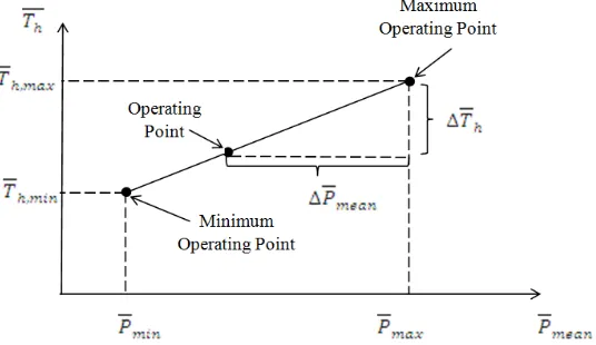
The basic concept of temperature control based on mean pressure control is shown in Figure 5. In the control of the heater temperature in the Stirling engine, the average temperature on the heater is conventionally measured using temperature sensors such as thermocouples [17]. The pressure reference setting Pmean is often calculated based on empirical static temperature-pressure droop characteristic, such as that shown in Figure 5 [17].
Figure 5. Pressure Versus Temperature Relationship with Droop Characteristic
The permanent droop DP is defined as the slope [18],
��=∆�∆�ℎ ����=
�ℎ,���−�ℎ,��� ����−���� =
1−�ℎ,���
1−�����
With the permanent droop DP, �ℎ is thus not maintained constant over the whole range of the insolation level. This is equivalent to the introduction of a proportional controller (P controller) with gain 1/DP into the temperature control system [19].
3.2. Modeling of Command Pressure Control
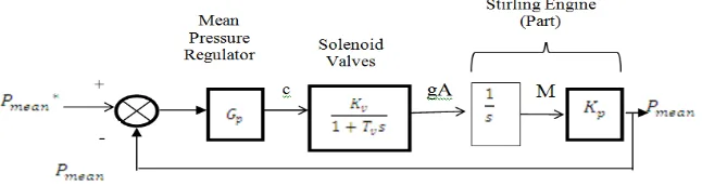
Figure 6. Block Diagram of MPC within the Temperature Control Scheme.
3.2.1. Command Pressure versus Total Mass Relationship, Kp
The linearized model is developed assuming the system is operating in the controlled temperature region [20]. In addition, the expansion and compression temperatures are assumed to be equal to the heater and cooler temperatures, respectively. Therefore the relationship between the quantity of working gas in the engine and the mean pressure is given by [21] and [22];
While in the adiabatic analysis, the mean value of the expansion space temperature is not the same as the heater temperature. Thus, to obtain more accurate values of B and K, Th and Tk should be replaced with the mean values of Te and Tc respectively.
The constant Kp is derived assuming the engine is in a steady state operation, and thus the total working gas mass M is assumed to be constant. Therefore the mean value of the pressure is calculated by integrating its defining equation over one revolution of the crankshaft. Therefore, the constant Kp defines the steady state pressure to be directly proportional to the total working gas mass.
3.2.2. Modelling of Solenoid Valve, Kv and Tv
The solenoid valves are modeled as a first order system, given by [21] and [22];
����(�) �(�) =
��
1+��� (2)
Where gASV is the mass flow in the solenoid valve (kg/s), C is the commanded mass flow rate, s is the Laplace transform variable, and Kv and Tv are the gain and time constant of the valve, respectively. The pressure of the storage tanks are assumed to be constant, and, according to [21] and [22], the mass flow through the open valve can be approximated by:
gA =ρx���2
4 (3)
Where ρ is the gas density (kg/m3), Dp is the pipe diameter (m), and x is given by:
x =�2��(���−�)
��� (4)
Where pst is the high pressure storage tank pressure (Pa), f is the friction factor, and L is the length of the pipe (m). Thus, assuming the minimum working gas pressure for p, the mass flow rate limit is a function of the pipe dimensions.
3.2.3. Controller Tuning, Gp
The resulting closed loop transfer function is of the same form as the normalized second order system often used in linear control theory, with the general form given [21] and [22]:
T(s) = ��2
�2+2 ξ ���+��2 (7)
Where ξ is the damping ratio and ωn is the natural frequency. The damping ratio is given by [21]
and [22]:
ξ = 1
2����= 1
2���������/�� (8)
The pressure controller gain Gp can thus be calculated by choosing a desired damping
ratio, where ξ = 0.7(fine tuning) and solving for Gp, given by [21] and [22]:
��=4��ξ21���
� (9)
Mean pressure control (MPC) can be considered as the inner loop of the temperature control scheme shown in Figure 6.
4. Conclusion
In 2013, it was recorded that the global CO2 emissions were 36 gigatonnes (GtCO2).
This is 61% higher than the Kyoto Protocol reference year (1990) and 2.3% higher than 2012. Meanwhile, in 2014, the global CO2 emissions are increase by an additional 2.5% over the 2013
level. With the extreme dependence on fossil fuels, an environmental problem such as excessive emissions of carbon dioxide (CO2) has created the world anxiety conditions.Thus, when considering scenarios of the renewable energy technology development and deployment, especially in the context of scaling down the global CO2 emissions, initial higher costs of
renewable energy should not be counted as barriers to the deployment. However, the control systems presented in this paper are designed to maximize Stirling engine efficiency during normal operation by maintaining the heater/absorber temperature at the highest safe operating point using Matlab /Simulink 2012a. Based on the developed linearized model, an improved temperature controller with transient droop characteristic and Mean Pressure Control (MPC) has been proposed. This temperature controller is effective in reducing the temperature and improved performance of the PD system.
Acknowledgements
References
[1] Dino. New Technologies for Sustainable Energy in the Smart City: the WET Theory. Tema. Journal of Land Use, Mobility and Environment. 2014; 7(1): 29-42.
[2] N Noor, S Muneer. Concentrating solar power (CSP) and its prospect in Bangladesh. Developments in Renewable Energy Technology (ICDRET), 1st International Conference. 2009: 1–5.
[3] Winter CJ, Sizmann RL, Vant-Hull LL. Solar Power Plants Fundamental, Technology, Systems, Economics. IEEE Symposium on FPGA for Custom Computing Machines. Napa. 2008: 226-232. [4] Andraka CE. Alignment Strategy Optimization Method for Dish Stirling Faceted Concentrators.
In ASME 2007 Energy Sustainability Conference, American Society of Mechanical Engineers. 2007: 1047-1054
[5] Zhang HL, Baeyens J, Degrève J, Cacères G. Concentrated solar power plants: review and design methodology. Renewable and Sustainable Energy Reviews. 2013; 22:466-481.
[6] Howard DF. Modeling, simulation, and analysis of grid connected dish-stirling solar power plants. 2010.
[7] Droher JJ, Squier SE. Performance of the Vanguard Solar Dish-Stirling Engine Module. Rockwell International Corp. Canoga Park, CA (USA). Energy Technology Engineering Center. Final report Number: EPRI-AP-4608. 1986.
[8] Washom BJ. Vanguard I solar parabolic dish-Stirling engine module. Advanco Corp. El Segundo, CA (USA). Final report number: DOE/AL/16333-2. 1984.
[9] Washom BJ. Vanguard I solar parabolic dish-Stirling engine module. Advanco Corp. El Segundo, CA (USA). Final report number: DOE/AL/16333-2).1984.
[10] Schiel W. Dish Stirling Activities at Schlaich Bergermann und Partner. SBP. In Workshop at NREL. 2007; 7.
[11] Pheng LG, Affandi R, Ab Ghani MR, Gan CK, Jano Z, Sutikno T. A review of Parabolic Dish-Stirling Engine System based on concentrating solar power. TELKOMNIKA (Telecommunication Computing Electronics and Control). 2014; 12(4): 1142-1152.
[12] Schertz PT, Brown DC, Konnerth III A. Facet development for a faceted stretched-membrane dish by Solar Kinetics. Sandia National Labs. Albuquerque, NM (United States). Solar Kinetics, Inc., Dallas, TX (United States). No: SAND-91-7009. 1991.
[13] Lopez CW, Stone KW. Design and Performance of the Southern California Edison Stirling Dish.
Proceedings of the 1992ASME International Solar Energy Conference. Maui, HI. New York. 1992; 2: 945-952.
[14] Shaltens RK, JG Schreiber. Preliminary Designs for 25 kW Advanced Stirling Conversion Systems for Dish Electric Applications. Proceedings of 25th IECEC. Reno, NV. 1990; 6: 310-316.
[15] Stone Shaltens RK, JG Schreiber. Status of the Advanced Stirling Conversion System Project for 25 kW Dish Stirling Applications. Proceedings of 25th IECEC. Reno, NV. 1990; 5: 388-394.
[16] Grossman JW, Houser RM, Erdman WW. Testing of the single-element stretched-membrane dish. Sandia National Labs. Albuquerque, NM (United States). No: SAND--91-2203. 1992.
[17] Schiel W. Personal communication. 1992.
[18] Holtz RE, Uherka KL. A study of the reliability of Stirling engines for distributed receiver systems. Sandia National Labs. Albuquerque, NM (USA); Argonne National Lab., IL (USA). Number: SAND-88-7028. 1988.
[19] Diver RB, Menicucci DF. Dish/Stirling for Department of Defense Applications. Sandia National Labs Albuquerque NM. Final Report number: SAND-97-0527. 1997.
[20] Dussinger PM. Design, Fabrication and Test of a Heat Pipe Receiver for the Cummins Power Generation 5 kW Dish Stirling System. Proceedings of 26th IECEC. Boston, MA. 1991; 5: 171. [21] DF Howard. Effects of variable solar irradiance on the reactive power compensation for large solar
farm. In Proceedings of IREP Symposium Bulk Power System Dynamics and Control. Rio de Janeiro, Brazil. 2010: 1-8.
[22] Li Y. Dish-Stirling solar power plants: modeling, analysis, and control of receiver Temperature.