DOI: 10.12928/TELKOMNIKA.v14i1.3291 555
Measurement and Evaluation of Tx/ Rx Antennas for
X-Band Radar System
Folin Oktafiani1*, Yuyu Wahyu1, Yusuf Nur Wijayanto1,2
1
Indonesian Institute of Sciences (LIPI), Jl. Sangkuriang, Cisitu, Bandung 40135 INDONESIA, Telp. +62-22-250-4660 Fax. +62-22-250-4660
2
National Institute of Information and Communications Technology (NICT), 4-2-1 Nukui-Kitamachi, Koganei, Tokyo 184-8795 JAPAN
*Corresponding author, e-mail: [email protected], [email protected]
Abstract
This paper presents the performance evaluation of antennas for microwave transmission and reception in X-band radar systems. The transmitter (Tx) and receiver (Rx) antennas are fabricated on microstrip array structures. The antennas are connected to microwave circuits with transmission lines, coaxial cables, and microwave combiners and splitters. The designed antennas in X-band microwave operation for Tx and Rx parts were fabricated identically by 4x64 microstrip patch antennas in an array structure. The fabricated antennas were measured for return loss (S11), VSWR, radiation pattern, and Gain. The detail methods for the measurements are reported and their results are also discussed. The measured antenna gain of ~20dBi, and beam width of ~20degree can be obtained using the fabricated antennas at 9.4GHz microwave operation.
Keywords: Microstrip antennas, array structure, radar system, X-band microwave
Copyright © 2016 Universitas Ahmad Dahlan. All rights reserved.
1. Introduction
Radar is a device that can be used to monitor the waters, air and land. There are various kinds of technology that can be used in radar systems, such as FMCW technology, Pulse, Pulse Compression etc. Each technology has advantages and disadvantages [1-5].
Radar system which designed in this paper uses FMCW technology with the following considerations, using low operation and maintenance cost, using small power transmit that will reduce costs, small size [6-8]. But its disadvantage, namely transmit and receive signals processing cannot use a single antenna, so that need two antennas for a transmitter and a receiver.
One part that has an important role in the radar system is antenna system. Antenna is a device that used to transmit and receive signals. If the antenna can transmit signal and receive reflected signal from the target by gain and radiation pattern that suitable to desired specifications, it will be able to detect the target precisely and accurately [9-11]. Some aspects that must be considered in radar designing are operating frequency associated with the application to be used, the antenna gain, beamwidth, target range, the resolution of the target detection, etc.
Radar that being designed is radar for navigation applications on vessels so that required a compact antenna design that can be installed on ships, therefore, used X-band frequency in consideration will minimize the dimensions of the antenna [12-14]. Additionally, antenna system that be designed should have a high wind resistance so that when the antenna radar rotates at a speed of 6, 7, 8, 9, 10 rpm, antenna rotates normally.
Antenna type that used is microstrip antenna, because it has small dimension, lightweight, ease to fabricate and low cost. One of microstrip weakness is it has low gain, so that to increase its gain then designed array microstrip antenna [15-20].
In order to see performance of antenna system that has been designed, antenna must be measured in the laboratory and the field. Based on that, we report the measurement methods and discuss its results in this paper. The characteristics of the antenna system are measured such as the return loss, gain, radiation pattern, and isolation to make sure that antenna has designed at desired frequency operation.
2. Antenna System 2.1. Whole Structure
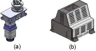
Figure 1(a) shows structure of radar antenna system. It is composed of several parts such as Tx/Rx antennas, antenna frame, radome, tilting mechanism, gearbox, and module box. The Tx/Rx antennas are arranged by mounting on the frame and by locking on tilting mechanism with elbow. The tilting mechanism has a function to adjust angle of the vertical direction of the antenna. It can be used to obtain optimum distance range of the radar. The shift angle of tilting mechanism is 10 degree towards the top and bottom.
(a) (b)
Figure 1. (a) Structure of the radar antenna system in whole-view, and (b) Structure of the antenna for Tx and Rx parts
The radar antenna system mainly consists of Tx and Rx antennas as shown in Fig. 1(b) They are located in the same place and rotate together. They are separated by an air gap to minimize mutual coupling effects and wind resistance. The Tx and Rx antennas are identically same structure include the shape and size. The Tx/Rx antennas are composed of eight antenna modules are arranged horizontally. In a one antenna module has 4 x 8 antenna array.
In order to protect the antenna system from unwanted weather condition such as high heat or heavy raining, a radome made from fiber material is used to cover the antenna system. The radome has a characteristic basically as an insulator. As a result, it has no affection to the antenna system performance. The designed radome consists of two parts to protect the Tx antenna in the upper side and the Rx antenna in the bottom side.
(a) (b)
In order to control the beamforming of the antennas, a motor is used to rotate the antenna systems in 360 degrees in azimuth direction. Illustration of the motor is shown in Figure 2(a). By using the mechanically beamforming, targets in 360 degrees in azimuth direction can be scanned. Since the Tx and Rx antennas are separated by the air gap, the antenna system becomes light and low wind resistance. Therefore, the motor operates smoothly with low load and low power consumption.
In the radar system antenna, RF circuits for front-end parts are also installed. The RF circuits such as a high power amplifier circuit before the Tx antenna and a low noise amplifier circuit after the Rx antenna. The RF circuits are arranged in a module boxes that is connected to the antenna system using a rotary joint. The position of module boxes in this radar as shown in Fig. 2(b) is close to the antenna system to minimize microwave loss of the system.
2.2. Tx/ Rx Antennas
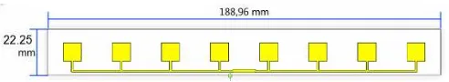
The Tx/Rx radar antenna is composed of eight modules are arranged horizontally as shown in Figure 3. In a single module, there are four rows of sub-module which form the arrangement of the eight patches horizontally, so in a single module there are 32 pieces of patches. The dimension of the antenna modules are 188.98mm in length and width 22.25mm. Picture of the fabricated of total antennas for Tx or Rx parts is shown in Figurre 3(a), and the picture of a single antenna module in front and back view respectively can be seen in Figure 3(b) and 3(c). Figure 3(c) shows that the antenna module consists of four insert port that serves as the feeding for each sub-module. The feeding is done by coaxial probe feeding technique which feeding process is start from the antenna ground plane and then penetrate through the substrate to connect the antenna patch on the top.
(a)
(b) (c)
Figure 3. Picture of the fabricated antennas (a) total antennas for Tx or Rx parts, (b) front view of the antennas, and (c) back view of the antennas
Figure 4. Design and parameters of the fabricated antenna sub-module
Antenna module is arranged in an array structure into a horizontal direction to generate high gain and narrow beamwidth corresponding to the desired specifications. Tx/ Rx antenna has the overall length 1511.68mm and width 89mm. The picture of the arrangement of eight antenna module which is the Tx/Rx antenna system can be seen in Figure 3(a).
The patch antenna is used with a square-shaped where the size set to 8.75 x 8.75mm2. The Tx/Rx radar antenna system is array that consists of 64 patches horizontally and 4 patches vertically. Distance between each horizontal patch is 14.75mm while each vertical patch is 14.25mm.
impedance of 50ohm. In order to obtain matching condition, the impedance adjustment is added by locating sub-modules with a length of 3.4 mm and a width of 1.2mm in the middle.
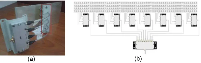
The antenna modules are arranged in array to enhance its performances. The modules are connected together to main input or output signals. It can be realized using power divider/ combiner with 4:1 and 8:1 [21-23]. Power divider/combiner 4:1consists of four inputs and one output on the receiver side, and one input and four outputs on the transmitter side. This also applied to the power divider/combiner 8:1. Semi-rigid cables are used as a link between feeding and in/ out power combiners. Selection of the appropriate combiner can minimize the loss generated in the process of divide/combine antenna modules. If the merger of feeding performed on the horizontal side first then needed four power dividers/combiners 8:1 so the semi-rigid cable to be used much longer and much more that will increase the loss. When the used semi-rigid cables are not in the same length, it will produce a different phase and will affect to performance of the antenna system. Based on this consideration, the mergers are done per module by connecting each feeding on a sub module. The distance between the semi-rigid must be constant because it will lead to the phase difference of the antenna. To keep the distance between the semi-rigid cables is used material as shown in Fig. 5(a) in red line. Configuration of the power divider/ combiner in the antenna systems can be seen in Figure 5(b). The output of the power divider/combiner 4:1 then combined with the power divider/combiner 8:1 to be connected to the main signal source.
(a) (b)
Figure 5. (a) Typical installation of the power combiner/ splitter in the antenna system, and (b) Configuration of the power combiner/ splitter in the antenna systems.
3. Experiment 3.1. Return Loss
Vector Network Analyzer (VNA) was used to measure the return loss and VSWR. Figure 6 shows the measured return loss and VSWR results of the fabricated antenna sub modules. The result shows the antenna has good return loss at desired frequency at 9.4GHz. Figure 6(b) shows the measured VSWR of the fabricated antenna which has an operation frequency of 9.356-9.517GHz with VSWR values of less than 1.5. The measured bandwidth of 161MHz was obtained. Based on the measurement results, the fabricated antennas have good agreement with the design specification.
(a) Return Loss (b) VSWR
(a) Return Loss (a) VSWR
Figure 7. The measurement of a single antenna module
Measurement of the combined four sub-module antennas using power divider/combiner is also necessary to ensure the combine process does not affect the value of return loss and VSWR. The measurement results of return loss and VSWR of the antenna modules are shown in Figure 7. We can see that the measurement results correspond to the designed specification.
3.2. Gain
There are two type of gain measurement method, absolute and comparison method. The comparison method needs a reference antenna with a certain gain. The antennas are often used as a reference is a dipole antenna λ / 2 and a horn antenna. A gain antenna measurement performed in this study using the comparative method. A horn antenna is used as a reference antenna. Port 1 of the Signal Generator is connected to the antenna source as a Transmitter (Tx) and port 2 on the Spectrum Analyzer is connected to the antenna to be measured (AUT) and the reference antenna that acts as a receiver (Rx). In the comparison method, the power received by the AUT and a reference antenna are compared. The minimum distance of far field between the transmitting antenna and the receiving antenna is expressed as follows:
= (1)
Where, is the minimum distance between transmitter and receiver (cm), is the largest dimension of the antenna (cm), and is the microwave wavelength (cm).
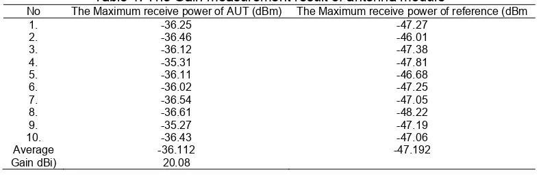
The measurement result of gain antenna is shown in Table 1. The measurement was done by comparing the maximum receive power of antenna under test with the maximum receive power of antenna reference [24, 25]. The measurement using horn antenna as a reference antenna with a frequency of 9.4GHz has 9dBi gain, so that the measurement gain antenna under test can be calculated by the equation:
(2)
Where, Pa is the maximum receive power of antenna under test, Ps is the maximum receive power of antenna reference, and Gs is the gain of antenna reference.
Table 1. The Gain measurement result of antenna module
No The Maximum receive power of AUT (dBm) The Maximum receive power of reference (dBm
1. -36.25 -47.27
2. -36.46 -46.01
3. -36.12 -47.38
4. -35.31 -47.81
5. -36.11 -46.68
6. -36.02 -47.25
7. -36.54 -47.05
8. -36.61 -48.22
9. -35.27 -47.19
10. -36.43 -47.06
Average -36.112 -47.192
In order to obtain accurate results, the measurement of the receive power done for several times. Then the average values of each receive power at the antenna under test and a reference antenna was taken. Furthermore the average value can be calculated for gain of antenna under test. The measured gain of a single antenna module is 20.08dBi.
3.3. Radiaton Patern
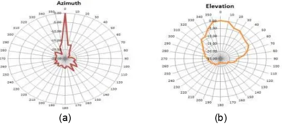
Antenna radiation pattern is a picture of antenna beam intensity as a function of spherical coordinates (Φ, ). The radiation pattern is obtained by making the pattern of elevation (Φ fixed, variable ) or azimuth pattern (Φ variable, fixed ). On the measurement of the radiation pattern, a horn antenna and antenna under test were used as a transmitter and receiver, respectively. The transmitting antenna was connected to the signal generator and the receiver antenna was connected to the spectrum analyzer [26, 27]. To get the azimuth and elevation radiation pattern, the radar antenna was rotated 360 degrees.
Measurement results for the radiation pattern of the fabricated antenna module are shown in Figure 8. Figure 8(a) is the measured radiation pattern in the azimuth with beamwidth of 10 degrees at -3dB. Figure 8(b) is the measured radiation pattern in the elevation with beamwidth of 20 degree at -3dB.
The antenna module of the first generation antenna system has an elevation beamwidth of 20˚, this value is obtained by the addition of reflectors so that the antenna radiation pattern can be focussed on a particular beamwidth angle. The elevation beamwidth of an antenna module on a second-generation radar antenna system is the same as the first generation. This proves that a vertical antenna array can reduce an elevation beamwidth without using the reflector.
(a) (b)
Figure 8. The Measurement result of radiation patern antenna module
4. Analysis 4.1. Gain
The gain measurement results of the antenna module is 20.08 dB, this was due to arrange the antenna array can improve the antenna gain. Antenna array will affect the number of radiating elements and aperture antennas. The more elements are used so the radiation emitted will also increase. The antenna gain is directly proportional to the antenna aperture as an equation of antenna gain. The array structure makes greater effective aperture that will affect the antenna gain,
Ae and (3)
4.2. Beam-width
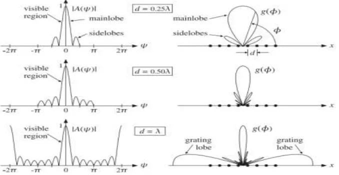
Figure 9 shows radiation pattern shape for 8 uniform array elements. Being greater the distance of each element, then the main lobe becomes narrower and side lobe becomes more. At antenna design uses 0.5λ for its distance isolation to get narrow main lobe and fewer sidelobe. The narrow beamwidth is required for radar antenna in order to get long range detection. To increase maximum detection range capabilities, the energy is concentrated into as narrow a beam as is feasible. Because of practical considerations related to target detection only the horizontal beam width is quite narrow, typical values being between about 0.65˚ to 2.0˚. The vertical beam width is relatively broad, typical values being between about 15˚ to 30˚.
Figure 9. Array factor and angular pattern of 8-element uniform array
To get narrow horizontal beamwidth for Tx/Rx antenna, so at antenna design uses 8 array antennas horizontally. Measurement result shows horizontal beamwidth is 1˚.
5. Conclusion
We have reported and presented the performance evaluation of antennas for microwave transmission and reception in X-band radar systems. The Tx and Rx antennas are fabricated on microstrip array structures. The designed antennas in X-band microwave operation for Tx and Rx parts were fabricated identically by microstrip array structure. The measurement methods and results were discussed in detail. The measured antenna gain of ~20dBi, and beam width of ~20 degree can be obtained using the fabricated antennas at 9.4GHz microwave operation. The antennas can be used to X-band radar system for surveillance applications. Furthermore, the proposed antennas can be used for future remote unit in the radar networks by combining with optical networks. Therefore they can be connected using optical fiber by adopting radio-over-fiber technology [28-30].
References
[1] M Skolnik. Radar Handbook. Third Edition. Mc Graw Hill. 2008.
[2] YK Chan, VC Koo. An introduction to synthetic aperture radar (SAR). Progress in Electromagnetics Research B. 2008; 2: 27-60.
[3] YN Wijayanto, A Kanno, H Murata, T Kawanishi, Y Okamura. Millimeter-Wave Radar Receiver Using Z-Cut LiNbO3 Optical Modulator with Orthogonal-Gap-Embedded Patch-Antennas on Low-k Dielectric Material. IEICE Transaction on Electronics. 2016; 98(8): 783-792.
[4] G Richard Curry. Radar Essentials: A Concise Handbook for Radar Design and Performance Analysis. SciTech Publishing Inc. 2012.
[6] M Jankiraman. Design of Multi-Frequency CW Radars. USA: Scitech Publishing Inc. 2007.
[7] AG Stove. Modern FMCW radar - techniques and applications. in Radar Conference, 2004, EURAD, First European. 2004: 149-152.
[8] Hao-Hsien Ko, Kai-Wen Cheng, Hsuan-Jung Su. Range resolution improvement for FMCW radars. In Radar Conference, 2008, EuRAD 2008, European. 2008: 352-355.
[9] CA Balanis. Modern Antenna Handbook. Wiley. 2018.
[10] Robert J Mailloux. Phased Array Antenna Handbook. Second Edition. Artech House. 2005.
[11] F Oktafiani, Y Wahyu, YS Amrulloh, Y Saputra, YN Wijayanto. Analysis of Corrugated Edge Variations on Balanced Antipodal Vivaldi Antennas. International Conference on Radar, Microwave, Electronics, and Telecommunication (ICRAMET) 2015. Bandung. 2015.
[12] Pearce D. A high resolution FMCW X-band radar sensor for vessel underway replenishment at sea applications. In Radar Conference, 2010 IEEE. 2010: 647-650.
[13] M Hajian, J Zijderveld, AA Lestari, LP Ligthart. Analysis, design and measurement of a series-fed microstrip array antenna for X-band INDRA: The Indonesian maritime radar. In Proc. 3rd Eur. Conf. Antennas Propag. Berlin, Germany. 2009: 1154-1157.
[14] Caruso M, Meta A, Corucci L, Lombardo P. An X-band FMCW radar for airports' perimeter surveillance. In Radar Symposium (IRS), 2013 14th International. 2013; 2: 853-858.
[15] R Garg, P Bartia, I Bahl, A Ittipiboon. Microstrip Antenna Design Handbook. Norwood: Artech House, Inc. 2001.
[16] VR Gupta, N Gupta. Characteristics of a Compact Microstrip Antenna. Microwave and Optical Technology Letters. 2004; 40(2): 158-160.
[17] R Mishra, P Kuchhal, A Kumar. Effect of Height of the Substrate and Width of the Patch on the Performance Characteristics of Microstrip Antenna.International Journal of Electrical and Computer Engineering (IJECE). 2015; 5(6): 1441-1445.
[18] Mashury Y Wahyu, AA Pramudita, P Daud. Coupled Patch Array Antenna for Surveillance Radar. The International Conference on Telecommunication Systems Services and Applications. Bandung. 2007.
[19] AF Morabito, T Isernia, L Di Donato. Optimal synthesis of phase-only reconfigurable linear sparse arrays having uniform-amplitude excitations. Progress In Electromagnetics Research. 2012; 124:405-423.
[20] Muhammad Darsono, Endra Wijaya. Circularly Polarized Proximity-Fed Microstrip Array Antenna for Micro Satellite. TELKOMNIKA Telecommunication Computing Electronics and Control. 2013; 11(4): 803-810.
[21] Mike Golio. The RF and Microwave Handbook. Second Edition. CRC Press. 2008.
[22] Jong-Sik Lim, Sung-Won Lee, Chul-Soo Kim, Jun-Seok Park, Dal Ahn, Sangwook Nam. A 4 : 1 Unequal Wilkinson Power Divider. IEEE microwave and wireless components letters. 2001; 11(3). [23] YP Saputera, AB Santiko, Taufiqqurrachman, M Wahab. Design dan Simulation of Combiner/Power
Divider 4x1 Methods Caviti Case for Application of LPI Radar X-Band Frequency. Proceeding on International Conference on Radar, Antenna, Microwave,Electronics and Telecommunication (ICRAMET). Batam. 2014.
[24] Hirano T, Iida Y, Hirokawa J, Ando M. Gain measurement of a horn antenna by shortened far-field technique with averaging. In Antenna Measurements & Applications (CAMA), 2014 IEEE Conference on. 2014: 1-3.
[25] HT Friis. A Note on a Simple Transmission Formula. Proc. of the IRE. 1946; 34(5): 254-256.
[26] Calazans T, Griffiths HD, Cullen AL, Davies DEN, Benjamin R. Antenna radiation pattern measurement using a near-field wire scattering technique. In Microwaves, Antennas and Propagation, IEE Proceedings. 1998; 145(3):.263-267.
[27] Du Zhou, Viikari Ville, Ala-Laurinaho Juha, Raisanen Antti V. 2D antenna radiation pattern retrieval using reflection coefficient measurement. Microwave Conference (APMC), 2014 Asia-Pacific. 2014: 846-848.
[28] H Murata, N Kohmu, YN Wijayanto, Y Okamura. Integration of Patch Antenna on Optical Modulators. IEEE Photonics Society News. 2014; 28(2).
[29] YN Wijayanto, D Mahmudin, P Daud. Proposal of Fiber-Remoted Radar Systems. Proceeding on International Conference on Radar, Antenna, Microwave, Electronics and Telecommunications (ICRAMET). Bali. 2012: 73-76.