ISSN 1818-4952
© IDOSI Publications, 2013
DOI: 10.5829/idosi.wasj.2013.21.1004
Corresponding Author: Zahriladha Zakaria, Centre for Telecommunication Research and Innovation (CeTRI), Faculty of Electronic and Computer Engineering, Universiti Teknikal Malaysia Melaka (UTeM), Hang Tuah Jaya,
Current Developments of Microwave Filters for Wideband Applications
Zahriladha Zakaria, Mohamad Ariffin Mutalib, Kamaruzaman Jusoff,
1 1 2
Mohd Sa’ari Mohamad Isa, Mohd Azlishah Othman, Badrul Hisham Ahmad,
1 1 1
Mohamad Zoinol Abidin Abd. Aziz and Shadia Suhaimi
1 3
Centre for Telecommunication Research and Innovation (CeTRI),
1
Faculty of Electronic and Computer Engineering, Universiti Teknikal
Malaysia Melaka (UT eM), Hang Tuah Jaya, 76100, Durian Tunggal, Melaka, Malaysia Department of Forest Production, Faculty of Forestry,
2
Universiti Putra Malaysia, 43400 UPM Serdang, Selangor, Malaysia Faculty of Business and Law, Multimedia University,
3
Jalan Ayer Keroh Lama, 75450, Melaka, Malaysia
Abstract: This paper presents a compilation of important review in the development of microwave filters for wideband technology used in previous years. The major research work for each year is reviewed. Several wideband filters based on the planar and non-planar circuits are compared and examined in order to propose a new topology of wideband filter using Suspended Stripline Structure (SSS). More importantly, this new proposed structure will be integrated with the Defects Ground Structure (DGS) to form an advanced hybrid system for wideband applications. This system will produce the band-pass and band-stop responses simultaneously in order to discriminate between the desired and undesired signals in the wideband spectrum. The proposed system outlined in this paper, featuring new innovation in hybrid structure as well as providing an insight of the direction of future research works. The contribution of this study is useful for applications where the reduction of physical volume is very important, while maintaining its good performance such as Ultra-Wideband (UWB), commercial radar as well as the wideband warfare receiver. As for future works, integration techniques between the UWB filter and DGS will be designed and analyzed to form an advanced new microwave device in order to produce bandpass and bandreject response in the same structure simultaneously.
Key words: Hybrid Microwave Device % Microwave Filter % Defected Ground Structure (DGS) % Suspended Stripline Structure (SSS)
INTRODUCTION Wireless technologies such as 802.11b and short-range In communication, the system can be termed as UWB products that would have a throughput capacity of wideband when the message bandwidth considerably 1,000 times greater than 802.11b (11 Mbit/sec). Those exceeds the coherence bandwidth of the channel. The numbers mean UWB systems have the potential to wideband bandwidth is forced to use for any support larger number of users, at much higher speeds communication link due to a high data rate. But another and lower costs than the current wireless LAN systems. link may have slightly low data rates intentionally use Current UWB devices can transmit data-up to 100 Mbps, a wider bandwidth in order to gain another advantage. compared to the 1 Mbps of Bluetooth and the 11 Mbps of The UWB is another modulation technique that uses the 802.11b. Moreover, it involves a fraction of current same purpose, follows on transmitting duration pulses. technologies like Bluetooth, WLANs and Wi-Fi [1].
Fig. 1: Untethered wireless UWB tracking system architecture (more slave sensors can be connected) [1]
UWB is a technology for transmitting information In designing the microwave filter, researchers focus which spreads over a large bandwidth (>500 MHZ) that on how to produce the wideband frequency and apply should, in theory and under the right circumstances, be them to ultra-wideband. In order to avoid the interference able to share spectrum with other users. Regulatory with WLAN radio signal, different methods and structures setting of Federal Communications Commission (FCC) in have been used to develop a UWB bandpass filter. United States is planned to offer an effective use of scarce In UWB, it has some interference with other signal radio bandwidth while allowing both great data rate frequency. Research on how to reject the unwanted signal “Personal Area Network” (PAN) wireless connectivity has to be developed and studied. A novel compact and longer-range, low data rate applications as well as structure that integrates bandpass filter and DGS in a radar and imaging systems [1]. single device to reduce the overall physical size will be UWB devices can be used for a multiplicity of discussed. The resulting structure will exhibit bandpass communications applications including the transmission and band reject response simultaneously. This will of very high data rates over short distances without overcome the problem face by the UWB application in suffering the effects of multi-path interference. UWB order to remove undesired signal, i.e. 5.2 GHz and 7.75 communication devices might be used to wirelessly GHz Wireless Local Area Network (WLAN) radio signal allocate services such as cable, phone and computer [1].
networking through a building or home. These devices In this paper, an effort has been made to describe and can also be used by police, fire and rescue personnel to show the exciting advances in microwave filter in term of provide undercover, protected communications devices. their technologies. The structure to produce the wideband Figure 1 shows the untethered wireless UWB tracking frequency signal is shown with some comparison based system architecture. The UWB can be used in various on planar and non-planar structure of the filter. This paper applications which widely used in the home environment. also shows the hybrid structure of integrating with DGS There are some advantages by using UWB in order to produce bandpass and bandstop filter frequency with the communication speed up to 1 Gbps simultaneously. From this structure, it provides small size, can be achieved for modern living. By utilizing Time of light weight and helps to reduce the cost of the Arrival (TOA) of UWB, the high resolution of 3-D manufacturing. It is expected that the information from location system can be reached. The interference between this paper will help researchers to get a broader electrical equipment can be decreased with less perspective of hybrid structure of the filter and perhaps penetration of the human body. The power consumption can be considered as an alternative to produce other could be minimized because less wireless communication methods.
devices is being carried. Some applications use the UWB
Laboratory, researchers were concentrating on the Basically, researchers are focusing on analysis, synthesis waveguide cavity filters for radar systems. In other and calculation of the microstrip circuit. It includes laboratories, the researches were conducted with different configuration, dimension and structure of the microstrip methods such as developed on broadband low pass, high conductor, while the ground side remains a complete pass and band pass coaxial filters and narrow-band metallization structure. However, by disturbing the tunable filter for receivers. The development of UWB ground plane structure, it can increase the effectiveness microwave filters has been increasing ever since the of capacitance and inductance. Some modifications are Federal Communications Commission (FCC) approved the needed to improve electrical performance and reduce the commercial use of UWB in 2002 [1]. Since then, there has size of microstrip circuit. In recent years, DGS structures been a considerable research effort geared into UWB with reconfigurable by active device have been radio technology worldwide. Radio Frequency (RF) filter investigated. Several solid state devices such as PIN or microwave filter is a type of passive device with two diode, Varactor or Tunnel Diode and Field Effect or portent works because it passes the desired signal and Bipolar Transistor can be used to vary the resonant blocks the unwanted signal. Filters are commonly frequency of DGS structure.
employed in microwave and millimeter-wave transceivers Due to the demand of wide operating frequency for as channel separators. Basically, it has four types of the UWB bandpass filter, this study offers a synthesis frequency responses which are lowpass, highpass, technique based on generalized Chebyshev characteristic bandpass and bandstop characteristics. A compact which is proposed to produce bandpass filter with sharp communication system works in this UWB frequency response and good performance. The main advantage of band require a small bandpass filter (BPF) with a notched the generalized Chebyshev characteristic is the finite band in the UWB passband in order to avoid being frequency can be mathematically placed at the location of interfered by the WLAN radio signals. two transmission zeros (pole-zero plot). Hence, it The defects in the ground plane and which have produces good selectivity and improve the filter’s disturbances in the shield current of distribution, either in performance Moreover, the number of elements can be etched periodic or non-periodic cascade configuration reduced by using this method and absolutely the defect, (e.g. microstrip, coplanar and conductor backed physical size can be decreased [6]. Therefore, the UWB coplanar waveguide) are known as DGS. This disturbance bandpass filter can be integrated with the DGS in order to occurs in the ground plane will alter the characteristics of remove undesired signal frequency within the UWB a transmission line such as line capacitance and frequency range. For example, in WLAN, the operated inductance. In other words, the effects of capacitance frequency of 5.2 GHz and 5.75 GHz can be eliminated. and inductance can be increased if the ground plane of Therefore, the integration technique can produce microstrip has a defect etched [3]. The DGS can also bandpass and band reject with the same structure eliminate the unwanted frequency which produces the simultaneously.
band rejection and the frequency range can be tuned by
controlling one physical dimension of DGS pattern [4]. Development of Microwave Filters for Wideband
Quasi-lumped inductive element was offered in DGS Application: The motivation of this study is driven by the structure. It can be used to replace the high impedance fact that for the UWB technology, UWB signals must narrow microstrip line which is normally used as an comply with the spectrum mask as required by the FCC inductor for designing high-low impedance low-pass filter Rules and Orders. Therefore, the design of UWB (LPF) [5]. The drawback with the very narrow width microwave bandpass filter is very critical in order to microstrip line section is the difficulty in fabricating the achieve broad bandwidth, while has the capabilities to LPF. In addition, the increased length of the filter will remove any undesired signal within the UWB frequency increase the dimensions of physical layout. Therefore, range. To provide the hybrid structure of the application, DGS acts as an inductor and can reduce the length of the the UWB can be applied at the microwave filter and DGS LPF. A resonant gap or slot in the ground metal is the to produce bandpass and rejection frequency signal basic element of DGS which placed directly under a simultaneously. In order to fulfill the satisfaction for the transmission line and aligned for efficient coupling to the users, this application can be used in the modern living;
line. PAN. Therefore, the suitable method which has been used
Fig. 2: Evolution of the proposed composite BFR[10] was discussed in [17]. However, the fractional bandwidths Several methods and structures have been studied in implemented and produced a cascading of cascadable order to develop new structures of these UWB filters. 180° hybrid rings by finite-ground coplanar waveguide UWB filter was produced by mounting a microstrip line in [18]. UWB with hybrid Microstrip-Coplanar waveguide a lossy composite substrate with the higher insertion loss was produced but the stopband frequency is still only [7]. However, at the lower frequency, the filter lacks of 16.0 GHz [19]. The structure in Figure 4 called an sharpness and produces a larger insertion loss which is asymmetric parallel coupled-line has been attempted in greater than 6.0 dB with poor impedance matching at the bandpass filter design [20] but their shape of transmission high frequency. In other studies, a microstrip ring UWB line has some difference in the shape proposed in [21]. is constructed by allocating transmission zeros below 3.2 The new method to produce UWB by using WLAN GHz and above 10.6 GHz [8, 9]. This filter with a ring notch was introduced [22, 23]. This UWB suspended resonator is larger in size and produces narrow, lower and stripline filter which has a single stopband by upper stopbands. The results show that, insertion loss is incorporating a resonant slot into one of its elements. better than 0.53 dB and return loss is greater than 10 dB in In this method, a Duroid RT 6010 substrate with a the passband from 3.8 GHz to 9.2 GHz and indicates the dielectric constant of 10.2 and a folded slot are selected to group delay below the 0.6 nsec within the passband ensure a resonance at a sufficiently low frequency. A slot
UWB. resonator is included into the patch to provide the
Hsu et al. [10] used a different technique to produce rejection of a small frequency band. The author connects
UWB by combining lowpass and highpass structures. a lowpass filter and highpass filter in series to improve the Figure 2 shows the evolution of the purpose composite upper stopband performance of the filter. The notch leads BFR. Both BPF consist of a hi-Z, low-Z LPF and an to some additional ringing of a transmitted Gaussian HPF structure designed with shunt quarter-wave monocycle, but the distortion is not very large compared short-circuited stubs separated by 8g/4 sections which act to a UWB filter without notch.
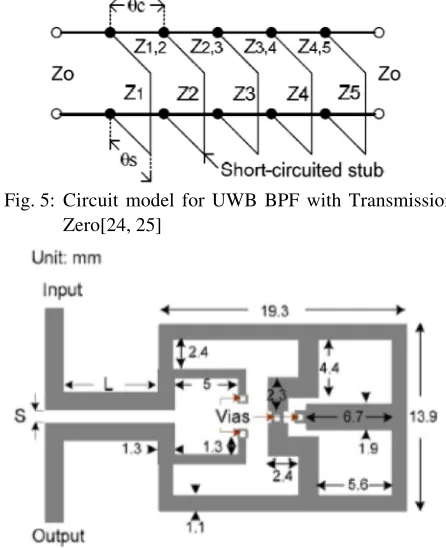
as impedance inverters. In [11-13], a broadside-coupled Shaman and Hong [24, 25] designed the compact Microstrip-coplanar Waveguide (CPW) structure with a UWB filter by using the short stubs to create tightened coupling degree is utilized to design an transmission zero. This paper proposed a filter with low alternative UWB filter with one, two and three sections. insertion loss, sharp rejection and excellent performance The two microstrip line are separated with a gap and both side and outside the band. For this method, the broadside coupled to one open-end CPW which is a basic purpose filter with five short-circuited stubs as section of the filter. The tight coupling will provide very demonstrated in Figure 5 has been designed for an wide bandpass operation. optimum stub filter whose connecting lines are The most important part of the structure in Figure 3 non-redundant. The conventional 9-pole Chebyshev filter is a broadside-coupled microstrip-coplanar waveguide will allow the filter to exhibit high selectivity.
(CPW). This structure is fabricated on the ground of the This filter in [25] is formed by using GML 1000 microstrip line. The reasons for introducing the extra high substrate with a relative dielectric constant of 3.05 and the rejection filter (HFR) are the BPF needs to have good thickness of 0.508 mm. This filter was fabricated on a bandpass performance and requires not only in-band but microstrip substrate and connected using the SMA also out-band. By using this type of structure, the connectors. The filter improved the response by performance of out-band up to 16 GHz with attenuation producing transmission zeros at desired frequencies. larger than 22 dB and the group delay is 0.27 ns. This was realized by placing the short-circuited stubs with
Zhu et al. [14] constructed a UWB BPF by using
Fig. 3: UWB BPF using broadside-coupled microstrip-coplanar waveguide structure [11]
Fig. 4: UWB BPF using Microstrip Stub-Loaded Tri-Mode Resonator [20]
Fig. 5: Circuit model for UWB BPF with Transmission and upper stopbands. This filter exhibited low insertion
Zero[24, 25] loss which includes the losses from the SMA connector
Fig. 6: Physical layout of UWB BPF with Pairs of this UWB filter. This method can increase the filter’s
Transmission Zeroes [25] selectivity.
two-section open-circuited stubs. However, in this technique, the size of the filter is increased significantly. The new technique is very simple for implementation by placing two sections of the feed lines of the length,
L parallel to each other separate spacing, S as shown in Figure 6.
The new transmission zeroes improved the filter performance outside the passband by widening the lower
(a) (b)
Fig. 7: (a) Equivalent circuit of four-resonator BPF with inductance feedback and (b) fabricated layout of UWB BPF [26]
Table 1: Comparison of different methods of UWB frequency
Filter/ Year f (GHz)o Fractional bandwidth, FBW (%) Insertion loss, S (dB)21 Return loss, S (dB)11 Size (mm )2
[7] 2003 6.8 - 6.7 >10 20×50
[8] 2004 6.5 1.5 0.53 >10
-[10] 2005 7.0 3 - >15 15×30
[11] 2005 6.83 - 0.32 >10 20×50
[13] 2005 5.63 - 0.5 >10 9.8×11.8
[14] 2005 6.85 - 0.55 >10 17×2.16
[20] 2008 7.0 90 0.5 >10 20×15
[21] 2011 6.8 - <1.0 >13 16×5
[25] 2007 6.85 110 0.3 >10 13.9×26.1
Figure 7(a) shows the circuit diagram for the four methods and design were presented in Table 1. Each coupled transmission which is used to replace the four design of filter has its own advantage. Some modifications resonators. The gap of transmission lines can control the can be made by improving the structure of a design in amount of coupling. This LTCC UWB filter is designed order to produce a hybrid structure which is DGS. using the substrate of Dupont 951, with a dielectric
constant of 7.8 and loss tangent of 0.0045. The compact Topology of Hybrid Structure: Bandpass filter is UWB filters have been widely investigated for highly commonly used by researchers and applied for the integrated low cost solutions by using LTCC technology wideband frequency. This study proposes a new hybrid and semi-lumped type filter circuits [27-30]. However, in structure which can be designed by combining the higher order, resonances were degraded and caused suspended stripline structure and DGS to produce the by parasitic electromagnetic (EM). Although the LTCC required results. DGS can produce the outstanding still suffers from certain temperature-related even the performance in terms of sharp selectivity at the cut-off packaging and miniaturizing were effective. frequency, spurious free wide stopband and ripples in the
A passive technology is applied by using PCB passband [29, 30, 32-34].
1 2 3 4 5 6 7
Fig. 8: (a) DGS in ground plane, (b) Equivalent circuit of DGS [35]
Fig. 9: Fabrication filter (a) Bottom view (b) Top view [37]
Fig. 10: Example of generalized Chebyshev lowpass
prototype filter (c)
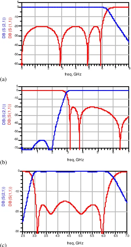
Bahmani et al. [37] designed a compact slot geometry Fig. 11: Preliminary Result for wideband frequency (a) to produce the DGS for a microstrip line. By using Lowpass filter at 6 GHz (b) Highpass filter at 3.1 U-shape slot, the capacitive of the structure and overall GHz (c) Bandpass filter at 3.1 to 6 GHz
length of the pattern can be increased. This design of LPF
produces the excellent stop band more than 30 dB from finite frequencies as shown in Figure 10. The suitable 2.8 to 10 GHz with 1.2 sharpness factor (f / fo c). Figure 9 lumped element needs to be chosen based on the number shows the fabrication structure of filter by applying the of order and attenuation of this design filter.
DGS. The measured filter has 3 dB cutoff frequencies at The lowpass prototype operates in a system 2.4 GHz and the insertion loss in the passband is less than impedance of 1 S and the cutoff frequency with 1 rad/s. 0.6 dB. The transmission zeros at 2.9 GHz enhanced the To convert from 1 S to 50 S impedance, all the circuit roll off and stopband rejection. elements must be scaled by 50 S. A lowpass filter with 6 There are some mathematical formulae that can be GHz cut-off frequency based on the generalized used in order to prove the method of designing the Chebyshev prototype of stopband insertion loss of bandpass filter. The design will start from the lowpass 60 dB and minimum passband return loss of 20 dB will be prototype network which satisfies a generalized used as a specification in the synthesis and mathematical Chebyshev response with two transmission zeroes at modelling. The lowpass filter prototype and its element
(a)
(a) to the incessant development in both theoretical filter
(b) radar as well as the wideband electronic warfare receiver.
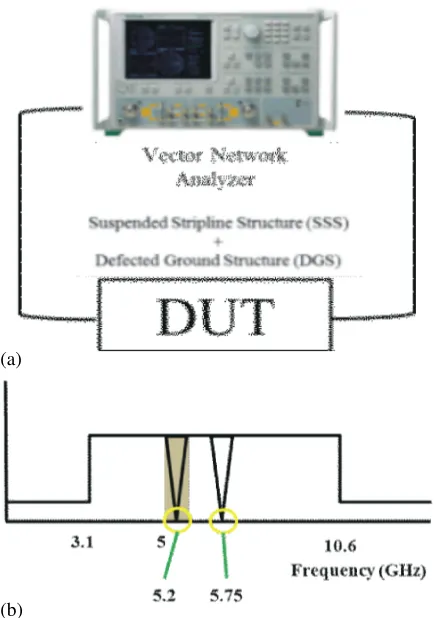
Fig. 12: (a) Method for Measuring Filter (b) Undesired between the UWB filter and DGS can be designed and signal at UWB spectrum analyzed to form an advanced new microwave device in values can then be constructed and transformed to the same structure simultaneously.
highpass filter in order to produce bandpass filter.
The formula to transform this design from lumped element ACKNOWLEDGEMENTS
to distributed circuit and lastly to suspended is provided
[38]. The authors would like to thank UTeM for
A combination of the lowpass and highpass filter in sponsoring this work under the short-term grant a cascaded method can produce a new class of bandpass UTeMPJP/2012/FKEKK(11C)/S01015.
circuit. The overall physical realization of the filter will be
implemented based on suspended stripline structure. In REFERENCES
this stage, the utilization of EM simulations will be
required as well as the analysis of S-parameter and 1. Revision of Part 15 of the Commission’s Rules electromagnetic fields. The analytical modelling of DGS Regarding Ultra-Wide-band Transmission System. will be established based upon a Dumbbell-shaped 2002. Federal Communication Commission, ET-structure by using a co-planar waveguide technology to Docket, pp: 98-153.
produce a band reject characteristic. A PIN diode will be 2. Levy, R. and S.B. Cohn, 1984. A History of introduced in the DGS in order to activate the band reject Microwave Filter Research, Design and response at the desired frequency. Development. Microwave Theory and Techniques,
A parametric study will be involved at this stage in IEEE Transactions, 32(9): 1055-1067.
order to identify and analyze the variation of DGS 3. Weng, L.H., Y.C. Guo, X.W. Shi and X.Q. Chen, 2008. parameters. Further tuning and optimization on the DGS An Overview on Defected Ground Structure. parameter will be carried out to obtain good appropriate Progress In Electromagnetics Research, 7(1): 173-189. responses. Figure 11 shows the preliminary results of the filter characteristics to produce a bandpass response which covers from 3.2 Ghz to 6 Ghz. Figure 12 (a) shows the measurement setup on the Device Under Test (DUT) using the Vector Network Analyzer (VNA) and Figure 12 (b) illustrates the undesired signals (5.2 GHz and 5.72 GHz) occur at UWB frequency that need to be removed.
CONCLUSION
In this paper, an effort has been made to relate some of the several advances in filter technology for modern applications such as in the UWB spectrum. This has led design methods and in the technology used for realizations. The hybrid technique for designing bandpass filter and defected ground structure is proposed in this study. This technology can be used for emerging digital home environment which can support the different consumer computer device, electronic device and mobile devices. It can be implied that microwave filters are not only restricted to UWB applications but can also be used in any wideband applications particularly in commercial It is recommended that the integration techniques
4. Yang, G., R. Jin, C. Vittoria, V.G. Harris and N.X. Sun, 16. Zhu, L., H. Bu and K. Wu, 2000. Aperture 2008. Small Ultra-Wideband (UWB) Bandpass Filter
With Notched Band. IEEE Microwave and Wireless Components Letters, 18(3): 176-178.
5. Hong, J.S. and M.J. Lancaster, 2001. Microstrip Filters for RF / Microwave Applications. New York: Wiley.
6. Mandal, M.K. and S. Sanyal, 2007. Compact Wide-Band Wide-Bandpass Filter Using Microstrip to Slotline Broadside-Coupling. Microwave and Wireless Components Letters, IEEE, 17(9): 640-642.
7. Saito, A., H. Harada and A. Nishikata, 2003. Development of Band Pass Filter for Ultra Wideband (UWB) Communication. Ultra Wideband Systems and Technologies, 2003 IEEE Conference, pp: 76-80. 8. Ishida, H. and K. Araki, 2004. Design and Analysis of UWB Bandpass Filter with Ring Filter. Microwave Symposium Digest, 2004 IEEE MTT-S International, 3: 1307-1310.
9. Cai, P., X. Guan, X. Yang, Y. Zhang, B. Chen, J. Huang and Y. Wu, 2009. Wideband Bandpass Filter Using Parallel-Coupled Line and Step-Impedance Open Stubs. 3 IEEE Internationalrd
Symposium on Microwave, Antenna, Propagation and EMC Technologies for Wireless Communications, 1(1): 1047-1049.
10. Hsu, C.L., F.C. Hsu and J.T. Kuo, 2005. Microstrip Bandpass Filters for Ultra-Wideband (UWB) Wireless Communications. Microwave Symposium Digest. 2005 IEEE MTT-S International, pp: 679-682. 11. Li, K., D. Kurita and T. Matsui, 2005. An Ultra-Bandpass Filter and Its Application to UWB Pulse Generation. 2005 IEEE International Conferenc Ultra-Wideband, 2005. ICU 2005, pp: 446-451.
13. Li, K., D. Kurita and T. Matsui, 2006. UWB Bandpass Filters with Multi Notched Bands. Microwave Conference, 2006. 36 European, pp: 591-594.th
14. Zhu, L., S. Sun and W. Menzel, 2005. Ultra-Wideband ( UWB ) Bandpass Filters using Multi-Mode Resonator. IEEE Microwave and Wireless Components Letters, 15(11): 796-798.
15. Zhou, Y., B. Yao, Q. Cao, H. Deng and X. He, 2009. Compact UWB Bandpass Filter Using Ring Open Stub Loaded Multiple-Mode Resonator. Electronics
17. Menzel, W., L. Zhu, K. Wu and F. Bogelsack, 2003. On the Design of Novel Compact Broad-Band Planar Filters. IEEE Transactions on Microwave Theory and Techniques, 51(2): 364-370.
18. Chi, C.H. and C.Y. Chang, 2006. Wideband Chebyshev-response Bandpass Filter By Cascading of Cascadable 180° hybrid rings. Proceedings of Asia-Pacific Microwave Conference 2006. Yokohama, Microwave Conference, 2008 China-Japan Joint, pp: 551-553.
21. Wang, Z.Q. and M.J. Wu, 2001. Effect Of Asymmetric Coupled-Line In Ultra-Wideband Filter Design. 2011 IEEE 13 International Conference on Communicationth
Technology, pp: 1046-1049.
22. Oudaya, C.S., R. Nakkeeran and K. Thirumalaivasan, 2010. Resonator Based Compact Ultra-Wideband and Notched Wideband Filters. 2010 National Conference On Communications (NCC), pp: 1-3.
23. Menzel, W. and P. Feil, 2006. Ultra-Wideband (UWB) Filter with WLAN Notch. Proceedings of the 36th
European Microwave Conference. Manchester, United Kingdom, pp: 595-598.
24. Shaman, H.N. and J.S. Hong, 2006. A Compact Ultra-Wideband (UWB) Bandpass Filter with Transmission Zero. Proceedings of the 36 Europeanth
Microwave Conference. Manchester, United Kingdom, pp: 603-605.
25. Shaman, H.N. and J.S. Hong, 2007. A Novel Ultra-Wideband (UWB) Bandpass Filter (BPF) with Pairs of Transmission Zeroes. IEEE Microwave and Wireless Components Letters, 17(2): 121-123.
27. Tang, C.W., Y.C. Lin and C.Y. Chang, 2003. 33. Wang, C.J., S.Y. Chen and Y.C. Lin, 2007. Realization of Transmission Zeros in Combline Filters Improvements of Microstrip Loop Filters. 2007 Using an Auxiliary Inductively Coupled Ground International Workshop on Anti-Counterfeiting, Plane. IEEE Transactions on Microwave Theory and Security and Identification (ASID), pp: 40-43. Techniques, 51(10): 2112-2118. 34. Wu, G.L., W. Mu, W. Dai and Y.C. Jiao, 2008. Design 28. Yeung, L.K. and K.L. Wu, 2003. A Compact Of Novel Dual-Band Bandpass Filter With Microstrip Second-Order LTCC Bandpass Filter with Two Finite Meander-Loop Resonator And CSRR DGS. Progress Transmission Zeros. IEEE Transactions on In Electromagnetics Research, 78(1): 17-24. Microwave Theory and Techniques, 51(2): 337-341. 35. Kumar, A. and A.K. Verma, 2009. Design of Compact 29. Chang, C.F. and S.J. Chung, 2005. Bandpass Filter Seven Poles Low Pass Filter Using Defected Ground Of Serial Configuration with Two Finite Structure. 2009 International Conference on Emerging Transmission Zeros using LTCC Technology. IEEE Trends in Electronic and Photonic Devices and Transactions on Microwave Theory and Techniques, Systems, 1: 349-352.
53(7): 2383-2388. 36. Lim, J.S., C.S. Kim, D. Ahn, Y.C. Jeong and S. Nam, 30. Chen, C.H. and K.H. Lin, 2008. Novel compact 2005. Design of low-pass filters using defected LTCC UWB bandpass Filter with Simple ground structure. IEEE Transactions on Microwave Semi-Lumped Circuit Model. International Theory and Techniques, 53(8): 2539-2545.
Conference on Microwave and Millimeter Wave 37. Bahmani, F., J. Nourinia, C. Ghobadi and S. Pirani,
Technology, 1: 147-149. 2011. A Novel DGS Applied to Design Lowpass
31. Seong, J.C., P.L. Sung and Y.P. Jae, 2012. 3- to 5-GHz Filter. 2011 19 Iranian Conference, Electrical Ultra-Compact Bandpass Filter With Independent Engineering (ICEE), 1: 5-9.
Transmission Zeros Using PCB Embedding Passive 38. Hunter, I.C., 2001. Theory and Design of Microwave Technology. IEEE Components, Packaging and Filters. The Institution of Engineering and Manufacturing Technology, 2(7): 1064-1069. Technology, Michael Faraday House, Six Hills Way, 32. Parui, S.K. and S. Das, 2007. Performance Stevenage, UK.
Enhancement of Microstrip Open Loop Resonator Band Pass Filter By Defected Ground structures. 2007 International workshop on Antenna Technology: Small and Smart Antennas Metamaterials and Applications, 1: 483-486.
![Fig. 2: Evolution of the proposed composite BFR[10]](https://thumb-ap.123doks.com/thumbv2/123dok/554188.65251/4.612.109.253.102.216/fig-evolution-of-the-proposed-composite-bfr.webp)
![Fig. 7: (a) Equivalent circuit of four-resonator BPF with inductance feedback and (b) fabricated layout of UWB BPF [26]](https://thumb-ap.123doks.com/thumbv2/123dok/554188.65251/6.612.108.473.100.209/fig-equivalent-circuit-resonator-inductance-feedback-fabricated-layout.webp)