GENERALIZED CHEBYSHEV MICROWAVE FILTER FOR WIDEBAND APPLICATIONS
LIM FENG SHENG
This report is submitted partial fulfillment of requirements for the award of Bachelor of Electronic Engineering (Telecommunication Electronics) With
Honours
Faculty of Electronic and Computer Engineering Universiti Teknikal Malaysia Melaka
ii
UNIVERSTI TEKNIKAL MALAYSIA MELAKA
FAKULTI KEJURUTERAAN ELEKTRONIK DAN KEJURUTERAAN KOMPUTER
BORANG PENGESAHAN STATUS LAPORAN
PROJEK SARJANA MUDA II
TajukProjek : GENERALIZED CHEBYSHEV MICROWAVE FILTER
FOR WIDEBAND APPLICATIONS
SesiPengajian : 1 1 / 1 2
Saya LIM FENG SHENG
mengaku membenarkan Laporan Projek Sarjana Muda ini disimpan di Perpustakaan dengan syarat-syarat kegunaan seperti berikut:
1. Laporan adalah hakmilik Universiti Teknikal Malaysia Melaka.
2. Perpustakaan dibenarkan membuat salinan untuk tujuan pengajian sahaja.
3. Perpustakaan dibenarkan membuat salinan laporan ini sebagai bahan pertukaran antara institusi pengajian tinggi.
4. Sila tandakan ( √ ) :
SULIT*
*(Mengandungi maklumat yang berdarjah keselamatan atau kepentingan Malaysia seperti yang termaktub di dalam AKTA RAHSIA RASMI 1972)
TERHAD** **(Mengandungi maklumat terhad yang telah ditentukan oleh
organisasi/badan di mana penyelidikan dijalankan)
TIDAK TERHAD
Disahkan oleh:
__________________________ ___________________________________
(TANDATANGAN PENULIS) (COP DAN TANDATANGAN PENYELIA) Tarikh:
Tarikh: 15 JUN 2012
Tarikh: ……….
Tarikh: ………
iii
“I hereby declare that this report is the result of my own work except for quotes as cited in the references.”
Signature : ………
iv
“I hereby declare that I have read this report and in my opinion this report is sufficient in terms of scope and quality for the award of Bachelor of Electronic
Engineering (Telecommunication Electronics) With Honours.”
Signature : ……….
Supervisor‟s Name : Dr. Zahriladha bin Zakaria
v
vi
ACKNOWLEDGEMENT
I would like to thank my project supervisor, Dr. Zahriladha bin Zakaria for his guidance throughout the project. Besides, I appreciated the idea of the project and helps given by my project supervisor.
In addition, I would like to thank my family for supporting me morally throughout my completion of the project. Last but not least, I would like to thank the faculty for giving a chance to take part on a project which is a requirement to fulfilling the bachelor degree where I had gained great experiences and knowledge.
vii
ABSTRACT
viii
ABSTRAK
ix
TABLE OF CONTENTS
CHAPTER TITLE PAGES
PROJECT TITLE i
STATUS REPORT FORM ii
DECLARATION iii
DEDICATION v
ACKNOWLEDGEMENT vi
ABSTRACT vii
TABLE OF CONTENTS ix
LIST OF TABLES xii
LIST OF FIGURES xiii
NOMENCLATURE xv
SYMBOLS xvi
1.0 INTRODUCTION
1.0 Introduction 1
1.1 Objective 2
1.2 Problem Statement 2
1.3 Scope of Work 2
1.4 Methodology 3
1.5 Organization of Report 3
2.0 LITERATURE REVIEW
x 2.1 Literature Survey of Generalized Chebyshev Filter 7
2.2 Principle of Filter Design Method 13
2.2.1 Image Parameter Method 13
2.2.2 Insertion Loss Method 15
2.3 Principle of Low Pass Filter Prototype 16 2.3.1 Generalized Chebyshev Lowpass Prototype 18
2.4 Microstrip Technology 19
2.5 Suspended Substrate Stripline Technology 20 2.6 Printed Circuit Board (PCB) Materials 22
2.6.1 Rogers RO4000® Series 23
3.0 METHODOLOGY
3.0 Introduction 26
3.1 Flow of Project 26
3.2 Example of Chebyshev Band Pass Design 29 3.3 Generalized Chebyshev Low Pass Filter Design 33
3.3.1 Generalized Chebyshev Low Pass 33 Prototype Design
3.3.2 Impedance and Frequency Transformation 34 3.4 Suspended Substrate Stripline Design Equations 36
3.5 Richard‟s Transformation 38
3.6 Generalized Chebyshev Lowpass Filter Utilizing 39 Suspended Stripline
3.7 Hardware Fabrication Process 41
3.8 Measurement Process 42
3.9 Summary 42
4.0 RESULT & DISCUSSION
4.0 Introduction 44
xi
4.2 Discussion 50
4.3 Summary 51
5.0 CONCLUSION & RECOMMENDATION
5.0 Introduction 52
5.1 Recommendation 52
5.3 Conclusion 53
REFERENCES 54
xii
LIST OF TABLE
NO. TITLE PAGES
2.1 Principle Properties of FR-4and Rogers RO4350B 22
3.1 The initial element values 30
3.2 Network element values before impedance scaling 31 3.3 Network element values after impedance scaling 31
xiii
LIST OF FIGURE
NO TITLE PAGES
2.1 Examples of frequency response of (a) High-pass 5 Filter (b) Low-pass Filter (c) Band-pass Filter
(d) Band-stop Filter
2.2 Block diagram of image parameter method 14
2.3 Block diagram of insertion loss method 15
2.4 Frequency response of Butterworth and Chebyshev 17
2.5 Low pass filter prototype 17
2.6 A generalized Chebyshev low-pass prototype filter having 18 three transmission zeros at infinity and (N-3) at a finite
frequency (b) The dual
2.7 The generalized Chebyshev insertion-loss response 19 2.8 (a) Microstrip line (b) Electric and magnetic field 20
distribution in the microstrip line
2.9 Suspended substrate stripline technology 21 2.10 RO4000 Series Materials Dielectiec Constant vs Frequency 24 2.11 RO4000 Series Materials Dielectric Constant vs Frequency 25
3.1 Project flow chart 28
3.2 4th degree Chebyshev capacitively coupled bandpass filter 32 3.3 Simulated response of the 4th degree Chebyshev 32
capacitively coupled bandpass filter
3.4 A generalized Chebyshev low-pass prototype filter having 34 three transmission zeros at infinity and (N-3) at a finite
xiv 3.5 7th degree generalized Chebyshev low pass prototype 34 3.6 Richard‟s transformation of lumped elements 39 4.1 Equivalent circuit of the 7th order generalized Chebyshev 45
low-pass filter
4.2 Simulated frequency response of the 7th order generalized 45 Chebyshev low-pass filter
4.3 Circuit of 7th order generalized Chebyshev low-pass 46 distributed filter
4.4 Simulated frequency response of the 7th order generalized 46 Chebyshev low pass distributed filter
4.5 Open and short circuited stubs design 47
4.6 Frequency response of stubs circuit 47
4.7 Generated layout using ADS Momentum 48
4.8 Simulation result of momentum layout 48
4.9 3D visualization using ADS Momentum 49
xv
NOMENCLATURE
ADS Advanced Design System
GHz Giga Hertz
MHz Mega Hertz
IEEE Institution of Electrical and Electronic Engineer
IL Insertion Loss
PLR Power Loss Ratio
RL Return Loss
RF Radio Frequency
TEM Transverse Electromagnetic Wave
xvi
SYMBOLS
% Percentage
Pi
λ Wavelength
Ω Ohm
Propagation Constant
C Capacitance
dB Decibel
fc Cut-off frequency
k Constant
l Length of stub
L Inductance
m M-derived Constant
N Number of order
n Number of order
S11 Return Loss
S21 Insertion Loss
CHAPTER 1
INTRODUCTION
1.0 Introduction
Radio frequency (RF) filter or microwave filter is a type of passive device with two ports network because it passes the desired signal and blocks the unwanted signal. Filters are commonly employed in microwave and millimeter-wave transceivers as channel separators. Basically, it have four types of frequency responses which are low pass, high pass, band pass and band stop characteristics.
In several industries such as satellite and airborne communication, there are continuous demands for smaller size, lighter weight, and lower manufacturing cost devices [1]. Therefore, size reduction has becoming a major design consideration for practical applications in broadband wireless access communication system. As the size of the RF filter decrease, the application system will become smaller in size.
2 1.1 Objective
The objective of this project is to design a generalized Chebyshev lowpass filter for wideband applications and to realize the filter using suspended stripline substrate.
1.2 Problem Statement
Even though the conventional Chebyshev microwave filter is designed with better rate of attenuation compared to other microwave filter, there are still improvement needs to be done in order to increase the performance of Chebyshev filter. For example, the conventional Chebyshev will produce amplitude variation in the passband and the transmission zeroes cannot be placed independently hence the selectivity of the filter is limited. The objective of the project is to design a generalized Chebyshev microwave filter for wideband applications and to minimize the cost of production of the generalized filter. The generalized Chebyshev will achieve higher selectivity and lower losses compared to conventional Chebyshev filter due to the transmissions zeros can be placed independently. Besides that, by reducing the number of the circuit order, the size of the generalized Chebyshev filter will be reduced.
1.3 Scope of Work
3 1.4 Methodology
This project is categorized to three major stages. The literature review and background study on the particular topics are done for the first stage to ease understanding in the filter techniques, characteristics and design concepts of the lowpass filter. The second stage will proceed on the construction and simulation of generalized Chebyshev protoptype using Advanced Design System (ADS) software. Next, the generalized 7th order Chebyshev lowpass filter are then physical transformed and em simulated. The last stage is the hardware fabrication on the generalized 7th order Chebyshev lowpass filter. This stage also involved measurement of the fabricated hardware and the measurement result is compared to the simulated result.
1.5 Organization of Report
This thesis consists of five chapters which are categorized as below to discuss on the project of generalized Chebyshev lowpass filter design.
Chapter 2 is the literature survey of the RF filter designs, which covers the background study on the miniaturized lowpass filter design and literature review on filter design theory. These will influence the selection of the filter design method and the techniques in the project.
Chapter 3 discusses the methodology of the project. The methods and procedures to design generalized Chebyshev lowpass filter is covered in this chapter.
Chapter 4 illustrates the simulations and measurement results of the band pass filter. Result analysis and discussion are covered in this chapter.
CHAPTER 2
LITERATURE REVIEW
2.0 Introduction
This chapter discusses the literature review of microwave filter design principles, microstrip technology, and the literature survey of miniaturized low-pass filter. The literature review in this chapter influences the selection of design methods and the characteristic polynomial function of the RF filter design.
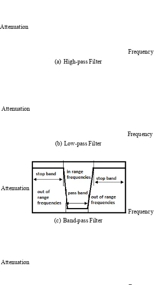
5
(a) High-pass Filter
(b) Low-pass Filter
(c) Band-pass Filter
[image:21.595.179.495.92.666.2](d) Band-stop Filter
Figure 2.1: Examples of frequency response of (a) High-pass Filter (b) Low-pass Filter (c) Band-pass Filter (d) Band-stop Filter [10]
Attenuation
Frequency
Attenuation
Attenuation Attenuation
Frequency
6 Figure 2.1 represents the frequency response with attenuation versus frequencies. For ideal filter, the pass-band indicates that there is no attenuation of signals whereas high attenuation discards signals in the stop band. Low pass filter passes low frequencies signals and rejects frequencies signals higher than the cut-off frequency. However, high pass filter passes high frequencies signals and attenuates frequencies signals lower than the cut-off frequency. Band pass filter, on the other hand, allows only a range of frequencies to pass through while attenuating frequencies signals outside the range. Vice versa, band stop filter rejects a range of frequencies while allowing frequencies outside band to pass through.
The RF filter design techniques or the characteristic polynomial functions that are commonly design are Butterworth, Chebyshev, Elliptic Function, Bessel, Linear Phase, and etc. Each of the characteristic polynomial function has different characteristic responses. Filter can be fabricated either on lumped element, distributed elements or both the combination. The parameters of interest of the filter are frequency range, bandwidth, stop band attenuation, transient response, and group delay. An ideal filter shows zero insertion loss, constant group delay over the required pass band, and infinite rejection elsewhere [11].
7 2.1 Literature Survey of Generalized Chebyshev Filter
In the research of Zlatoljub D. Milosavljevic [13], a class of generalized prototype filters with asymmetrically located transmission zeros was designed. The frequencies of extreme values of magnitude characteristic in the stopband are obtained by solving a set of non-linear equations. In this research, an exact, efficient and simple procedure was presented for the calculation of transmission zeros, for a class of generalized Chebyshev low-pass prototype filters with a maximum of two asymmetrically located transmission zeros of a multiplicity. The transmission zeros can be of arbitrarymultiplicity, and their maximum number is four. The frequencies of magnitude characteristic extreme values in the stopband have been obtained in closed form. Transmission zeros have been calculated by solving nonlinear equations and new equations for zero orders of maximally selective filters with equiripple stopband characteristic have been presented. The generalized Chebyshev prototype is one of themost useful because it combines the equiripple amplitude characteristic with the arbitrary position of transmission zeros in the complex plane. These filters are suitable for realization in different technologies, e.g., ceramic technology, cavity, and waveguide filters, etc., and can be used in handsets, base-station, and satellite applications, etc. Three examples have been given. One of them has verified transmission zeros calculation procedure, another has presented the synthesis procedure for the prototype, and the third has shown a realized ceramic filter for handset applications.
8 obtained results show that the proposed designed filter gives lower Q values of complex poles with a considerable value of flatness of the filter passband response.
In another research done by Jian-Yu Li, Chun-Hsiang Chi, and Chi-Yang Chang [14], a systematic and analytical method for the exact synthesis of generalized Chebyshev wideband hybrid ring based bandpass filters with a controllable transmission zero pair is developed. The basic configuration of the proposed filters consists of a hybrid ring, a multi-section short-circuited stub and a multi-section open-circuited stub. In this configuration, the position of the controllable transmission zero pair can be easily designed by setting the impedances of the multi-section short-circuited stub and the multi-multi-section open-circuited stub. According to the position of the controllable transmission zero pair, two kinds of filters are proposed. The filter has controllable transmission zero pair on the real axis (imaginary frequency) that they can be arranged to improve the group delay flatness. On the other hand, the filter has a controllable transmission zero pair on the imaginary axis (real frequency) and the desired stopband suppression can be obtained by adjusting the optimal position of them. This synthesis method is developed to obtain the impedance value of each line section and ripple factors of the filters with respect to given specifications (center frequency, passband bandwidth and transmission zeros).