! " #$ % & ' ( )
Transformation of Generalized Chebyshev Lowpass
Filter Prototype to Suspended Stripline Structure
Highpass Filter for Wideband Communication
Systems
Z. Zakaria1, M. A. Mutalib2, M. S. Mohamad Isa3, N. A. Zainuddin4
Centre of Telecommunication Research and Innovation (CeTRI), Faculty of Electronic and Computer Engineering, Universiti Teknikal Malaysia Melaka (UTeM), Hang Tuah Jaya 76100, Durian Tunggal, Melaka, Malaysia
1
[email protected], [email protected], [email protected], [email protected]
—
!"
#$% & '
( ')* +% , ɛ
*-. %
/-0
0 .
'12
, 0
I. INTRODUCTION
With the fast development of wireless communication, microwave filters with characteristics of high performance, low:cost, low insertion loss (IL) and compact are highly desirable for the next generation wireless communication system. Filter design starts with a classical lowpass lumped: element equivalent circuit or prototype. The equivalent circuit consists of series and shunt inductance and capacitor and their combination to form either series or parallel resonators [1][2][3]. The main advantage of generalized Chebyshev is mathematically can place a finite frequency at the location of two transmission zeros. Moreover it produces a good selectivity and enhances the filter’s performance [4].
A microstrip ring resonator with stubs is studied in [5] to design a wideband filter by utilizing its first three resonant modes. However, a lack of strength in capacitive coupling between the feeding:lines and ring, made the filter unable to produce a good response with wide bandwidth. The compact suspended stripline resonator is present in [6] which produce a
microwave filter by using resonator. This design has increased the capacitive loading of the resonator but it is difficult to control the return loss below than :20 dB. In [7], the filter is design using optimum distributed short circuited stubs method. However, this design did not produce narrow curve rejection at insertion loss.
In this paper, the transformation of generalized Chebyshev from the lowpass filter prototype to highpass filter is presented. As proof of concept, the highpass filter is designed at a cutoff frequency of 3.1 GHz with minimum stopband insertion loss of 40 dB at 2.5 GHz and minimum passband return loss of :20dB. The performance of generalized Chebyshev characteristic is better that the conventional Chebyshev particularly in term of its selectivity due to the transmission zeros can be placed at desired finite frequency. Thus, the generalized Chebyshev reduces the number of elements used in prototype and subsequently reducing the overall circuit dimensions. The filter design is designed based on suspended stripline structure (SSS) to exhibit a pure transverse electric:magnetic (TEM) mode of propagation and resulting in very low loss characteristics and excellent selectivity. The design has very sharp rejection which easier to determine the minimum stopband insertion loss.
II. DESIGN OF LOWPASS FILTER
! " #$ % & ' ( ) IL = 1 + ϵ cosh N − 3 cosh ω ω − ωω − 1
+ 3cosh ω
(1) where the transmission zeros are based on order ( :1) at
ω = ± and one at infinity. N is an odd number equal to the degree of the network,
= !10#$⁄ − 1& / (2) and RL is the minimum return loss level (dB) in the passband.
III. DESIGN OF HIGHPASS FILTER
In this section, a systematic filter development using the lowpass filter prototypes as a starting point will be demonstrated. A dual type of the generalized Chebyshev lowpass prototype filter is used as described in Section II. This dual type of lowpass prototype will satisfy the generalized Chebyshev with three transmission zeroes. The transformation to highpass filter is given by [9].
→− ) (3)
where )is cutoff frequency
This maps the lowpass filter prototype cutoff frequency to a new frequency. The transformation is applied to inductors and capacitors, where
*+= 1
), (4)
,+= 1 )*
(5)
Hence the inductors are transformed into capacitors and capacitors are transformed into inductors as shown in Figure 1. The component values of the prototype highpass filter are shown in Table I.
(a)
Figure 1: Seventh:degree generalized Chebyshev highpass filter prototype network
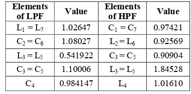
TABLE I:COMPONENT VALUE FOR PROTOTYPE LUMPED ELEMENTS
3
451 6
3
"51 6
L1 = L7 1.02647 C1 = C7 0.97421
C2 = C6 1.08027 L2 = L6 0.92569
L3 = L5 0.541922 C3 = C5 0.90904
C3 = C5 1.10006 L3 = L5 1.84528
C4 0.984147 L4 1.01610
To verify the theory, the device is constructed using Roger RO4350 with relative dielectric constant, -.= 3.48, substrate height, = 0.168 mm. The thickness of copper 0.035 mm and the loss tangent is 0.019. The highpass filter with cut:off frequency of 3.1 GHz with the degree, N = 7, the minimum stopband insertion loss of :40 dB at 2.6 GHz and minimum passband return loss of :20 dB are designed using the equation shown in (1) and (2). The elements values for the lowpass prototype network show in Table I with its corresponding ωo =
1.29516 rad/s can be obtained in [8].
The next step is to perform the impedance scaling with 50
Ω. After scaling to 50 K the values of the equivalent circuit for
each lumped component are shown in Table II
TABLE II:COMPONENT VALUE OF LUMPED ELEMENTS
3 6
*+
= *2+ 1.0003 pF
,+ = , 3
+ 2.3763 nH
*4+= *5+ 1.02619 pF
,+4= ,5+ 4.7368 nH
,+6 2.6084 nH
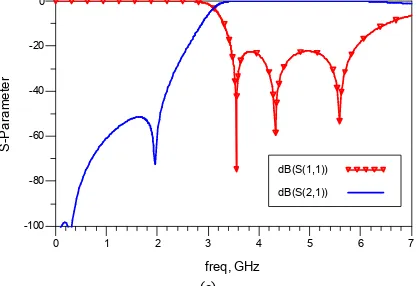
The highpass filter circuit can now be simulated using the Advance Design System (ADS) as seen in Figure 2 (a) and the response is shown in Figure 2 (b). It is observed that the filter has a cutoff frequency of 3.1 GHz which are in excellent agreement with the design specification.
(b)
Figure 2 : (a) Seventh:degree generalized Chebyshev highp Simulated frequency response of the generalized Chebyshev
! "
For realization, the lumped element highpass f transformed to open: and short:circuit transm segments by applying Richard’s transformation. Chebyshev highpass filter distribution can be cons applying Richard’s transformation to the high prototype in Figure 1. Under this transformation, transformed into an open:circuited stubs with admi
78=,9 .
and the resonator in the prototype has an impedanc
: ; = ; ,.− ;* .
The Richard’s transformation allows to repla inductors with short circuited stubs of impedance :8= , and capacitors with open circui characteristic impedance :8= 1 *⁄ . The resonator can be represented as admittance of an open circui characteristic admittance 9 * 2⁄ .
The length of the stub is one quarter wavele Constant = can be obtained by applying transformation at the band edge. The structure of element after applying the Richard’s transformation in Figure 3. The values of short: and open:circui shown in Table III. The electrical length of 30 obtain a broader passband bandwidth.
TABLE III:ELEMENT VALUE OF STUB ELEMENT Chebyshev highpass filter
pass filter is then rcuit transmission line nsformation. Generalized n can be constructed by to the highpass filter nsformation, inductor is ubs with admittances
(6)
an impedance
(7)
ows to replace lumped tubs of characteristic h open circuited stubs of he resonator impedance n open circuited stub by
uarter wavelength at . y applying Richard’s structure of distributed transformation is shown circuit stubs are
Figure 3 : (a) Generalized Chebyshev highpass frequency response of the generalized Chebyshe
The simulated results show an inserti 0 dB and return loss (#$$) better than the passband. A transmission zero at fi GHz is observed.
% # # # &###'
Figure 4 : Suspended Stripline
This highpass filter is simulated Figure 4) in order to improve the overa The impedance of the SSS which is Electromagnetic (TEM) transmission line capacitance to ground per unit length as t
, 3
highpass distributed filter (b) Simulated ed Chebyshev lowpass distributed filter
ow an insertion loss (#($) is almost nsmission line is related to its static
gth as the following [10]:
! , 3
- ./0
&1"1 22
: ?-.=377
*
-where -. is the dielectric constant of the medium the normalized static capacitance per unit len transmission line. If a transmission line is susp normalized static capacitance would include capacitance.
*
- = 2*A+4*′-C and
*A= E − F 2D ⁄
For a printed circuit, is assumed as zero and hence
* - =
4D E + 1.84
Therefore the line width can be obtained as:
D =E4 377: − 1.84
where is a ground plane spacing in mm characteristics of impedance line.
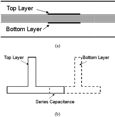
In order to realize the highpass filter capacitors and resonators can be approx inhomogeneous couple lined realized in suspende A series capacitance can be realized in the form coupled structure, overlapping of strips on the top layers of the substrate as shown in Figure 5.
(a)
(b)
Figure 5 : Layout of highpass filter using series capacitance and shunt stubs (a) cross section (b) top view
To produce a wider bandwidth, the value o impedance became too small to fabricate effe separation. This limitation can overcome in
! " #$ %
(8)
the medium and * - is per unit length of the line is suspended, the ould include fringing
(9)
pacitance and open circuited
the value of necessary fabricate effect of line vercome in suspended
stripline where the larger impedance can broadside:couple lines.
The series capacitors are represented b possessing capacitance *S. The length
T =1.8 U :88*S ?-H where U is the phase velocity and impedance and is given by replacing J
For the series resonators, the cap represented by the length of overlappi calculated from (13) and (16). The nea them means tighter coupling results in a 3:D physical layout of the highpass filte (a). The current flow visualization of t shown in Figure 6 (b). The SSS simulated and optimized using ADS simulated response are shown in Figure show an insertion loss (S21) is almost
(S11) better than :20 dB are obtained in t
a noted transmission zero occurs at aroun
(a)
(b)
#$ % & ' ( )
pedance can be produced by using
ODJ + 1.444VW (13)
1 QX (14)
(15)
constant of substrate and G8 is the
represented by an overlapping line he length overlaps is given by
(16) ng results in a better selectivity. The highpass filter is shown in Figure 6 ualization of the physical layout is SSS highpass is modeled, using ADS Momentum and the Figure 6 (c). The results ) is almost 0 dB and return loss obtained in the passband. There is
! " #$ % & ' ( )
(c)
Figure 6 : (a) 3:D view of Generalize Chebyshev highpass filter (b) Momentum visualization of highpass filter (c) Simulated frequency response of the generalized Chebyshev highpass filter in suspended stripline structure
IV. CONCLUSION
A transformation of the generalized Chebyshev lowpass filter prototype to the highpass filter has been presented. Simulation result from EM simulation produce an excellent agreement with the ideal circuit. This study can be further explored by integrating the generalized Chebyshev lowpass filter and highpass filter based on SSS technology. This work can be simulated and fabricated in future work by cascading the lowpass filter and highpass filter to produce a bandpass filter characteristic. In addition, a defected stripline structure (DSS) can also be proposed to exhibit a sharp notch response in the integrated lowpass and highpass filter in order to remove the undesired signals in the wideband applications. This type of generalized Chebyshev characteristic which offers good selectivity is very useful to minimize the overall filter size because it requires a lesser number of elements in the circuit compared to conventional Chebyshev characteristic. Therefore, this new class of microwave filter would be useful in any microwave communication systems where the reduction of overall physical volume is very important while
still maintaining the good performance such as in ultrawide band (UWB) and radar applications.
ACKNOWLEDGMENT
The authors would like to thank UTeM for sponsoring this
work under the short term grant, UTeM,
PJP/2012/FKEKK(11C)/S01015.
REFERENCES
[1] Z. Zakaria, I. C. Hunter, and A. C. Guyette, “Design of Coaxial
Resonator Filter with Nonuniform Dissipation,” IEEE MTT:S International Microwave Symposium Digest, pp. 623–626, 2008.
[2] Z. Zakaria, B. H. Ahmad. Design of SIW Bandpass Filter with 6 dB
Offset. IEEE RF and Microwave Conference (RFM), pp.87:90, 2011.
[3] Z. Zakaria, A. Sabah, W. Y. Sam. Design of low:loss coaxial cavity
bandpass filter with post:manufacturing tuning capabilities, IEEE Symposium on Business, Engineering and Industrial Applications (ISBEIA), pp. 733 – 736, 2012.
[4] Z. Zakaria, M. A. Mutalib, K. Jusoff, M. S. Mohamad Isa, M. A.
Othman, B. H. Ahmad, M. Z. A. Abd. Aziz, and S. Suhaimi, “Current Developments of Microwave Filters for Wideband Applications,” World Applied Sciences Journal, vol. 21, pp. 31–40, 2013.
[5] Sun, S. and Zhu, L. Wideband Microstrip Ring Resonator Bandpass
Flters Undermultiple Resonances, IEEE Trans. On Microw. Theory and Tech., Vol. 55, No. 10, pp. 2176:2182, 2007.
[6] R. Ruf and W. Menzel, “A Novel Compact Suspended Stripline
Resonator,” IEEE Microwave and Wireless Components Letters, vol. 22, no. 9, pp. 444–446, Sep. 2012.
[7] S. K. Singhal, D. Sharma, and R. M. S. Dhariwal, “Design of 1.3 GHz
Microstrip Highpass Filter Using Optimum Distributed Short Circuited Stubs,” 2009 First International Conference on Computational Intelligence, Communication Systems and Networks, pp. 264–267, Jul. 2009.
[8] S. A. Alseyab, “A Novel Class of Generalized Chebyshev Low:Pass
Prototype for Suspended Substrate Stripline Filters,” IEEE Transactions on Microwave Theory and Techniques, vol. 30, no. 9, pp. 1341–1347, 1982.
[9] C. Bowick, RF Circuit Design, Second. United State of America:
Newnes, p. 256, 2007.
[10] I. Hunter, Theory and Design of Microwave Filters. London, United
Kingdom: The Institution of Engineering and Technology, 2001.
! , 3
*+ *, * *
*
- ./0
"
*
#
&1"1 22