i
PC BASED DC MOTOR SPEED CONTROLLER
AINUL IZZATI BT ZAKARIA
This report is submitted in partial fulfillment of this requirement for the award of Bachelor of Electronic Engineering (Industrial Electronic) With Honors
Faculty of Electronic and Computer Engineering Universiti Teknikal Malaysia Melaka
ii
UNIVERSTI TEKNIKAL MALAYSIA MELAKA
FAKULTI KEJURUTERAAN ELEKTRONIK DAN KEJURUTERAAN KOMPUTER
BORANG PENGESAHAN STATUS LAPORAN
PROJEK SARJANA MUDA II
Tajuk Projek : PC Based DC Motor Speed Controller Sesi Pengajian : Januari 2009
Saya AINUL IZZATI BT ZAKARIA………... (HURUF BESAR)
mengaku membenarkan Laporan Projek Sarjana Muda ini disimpan di Perpustakaan dengan syarat-syarat kegunaan seperti berikut:
1. Laporan adalah hakmilik Universiti Teknikal Malaysia Melaka.
2. Perpustakaan dibenarkan membuat salinan untuk tujuan pengajian sahaja.
3. Perpustakaan dibenarkan membuat salinan laporan ini sebagai bahan pertukaran antara institusi
pengajian tinggi.
4. Sila tandakan ( √ ) :
SULIT*
(Mengandungi maklumat yang berdarjah keselamatan atau kepentingan Malaysia seperti yang termaktub di dalam AKTA RAHSIA RASMI 1972)
TERHAD* (Mengandungi maklumat terhad yang telah ditentukan oleh organisasi/badan di mana penyelidikan dijalankan)
TIDAK TERHAD
Disahkan oleh:
__________________________ ___________________________________
(TANDATANGAN PENULIS) (COP DAN TANDATANGAN PENYELIA)
Alamat Tetap: ………...
iii
“I hereby declare that this report is result of my own effort except for works that have been cited clearly in the references.”
Signature :
iv
“I hereby declare that I have read this report and in my opinion this report is sufficient in terms of scope and quality for the award of Bachelor of Electronic Engineering (Electronic Industrial) with Honours”
Signature : ……….
Supervisor‟s Name : En. Chairulsyah Bin abd Wasli
v
ACKNOWLEDGMENT
vi
ABSTRACT
vii
ABSTRAK
viii
TABLE OF CONTENT
CHAPTER TITLE PAGE
TITLE i
STATUS FORM ii
DECLARATION iii
DEDICATION iv
ACKNOWLEDGEMENT v
ABSTRACT vi
ABSTRAK vii
TABLE OF CONTENT viii
LIST OF FIGURE xi
LIST OF TABLE xiii
I INTRODUCTION 1
1.1 Introduction 1
1.2 Objectives 2
1.3 Problem Statement 2
1.4 Scope 3
ix
II LITERATURE REVIEW 5
2.1 Background Study 5
2.2 Introduction 6
2.3 DC Motor Starter 7
2.4 DC Motor Component 8
2.5 Permanent Magnet Motor 8
2.6 DC Motor Constant 11
2.7 Formula 12
2.8 Parallel Port 13
2.9 Speed Control 17
III METHODOLOGY RESEARCHES 21
3.1 Introduction 21
3.2 Hardware Development 24
3.3 Astable Operation 26
3.4 Brushless DC Motor 28 3.5 Software Development 30
x
IV RESULTS 35
4.1 Expected Results 35
4.2 Hardware Results 36
4.3 Hardware Operated By
Manual 37
4.4 Software Results 38
4.5 Actual Results 41
V DISCUSSION AND CONCLUSION 42
5.1 Discussion 42
5.2 Conclusion 44
5.3 Suggestion 44
REFERENCES 45
APPENDIX A 47
APPENDIX B 49
APPENDIX C 51
APPENDIC D 54
APPENDIX E 57
xi
LIST OF FIGURE
FIGURE TITLE PAGE
2.1 Permanent Magnet 9
2.2 Speed Tolerance Characteristic 9
2.3 Voltage Effected On Speed 10
2.4 D-25 Type Male Connector 16
2.5 Manual Speed Control 18
2.6 Shunt Field Rheostat 18
2.7 Armature Current 19
2.8 Variable Voltage Connected 20
3.1 Block Diagram of PC Based DC
Motor Speed Controller 22
3.2 Flow Chart 25
3.4 The 555 Timer Connected As An
Astable Multivibrator 26
3.5 Operation of the 555 Timer In The
Astable Mode 27
3.6 Frequency of Oscillator as s
xii
3.7 Schematic Interface Circuit 30
3.8 PCB For Interface Circuit 31
4.1 Hardware Circuit 36
4.2 Infrared Receiver Circuit 36
4.3 Infrared Transmitter Circuit 36
4.4 Interface Circuit 36
4.5 Result after Press the Key of
Compile 38
4.6 The Result after Wait a Few
Second 38
4.7 The Result after Press The
„ENTER‟ Key 39
4.8 The Result after Choice 1 39
4.9 The Result after Choice 2 40
4.10 The Result after Choice 3 40
xiii
LIST OF TABLE
TABLE TITLE PAGE
2.1 Pin Number and Function 14
2.2 Pin Direction and Associated
Register 15
xiv
CHAPTER I
INTRODUCTION
1.1 INTRODUCTION
xv
1.2 OBJECTIVES
The objectives for this project are:
To learn the concept of electrical DC motor system and the speed controlling system.
To learn and implement about the Visual Basic.
To learn troubleshooting and analyzing.
To design and implement the circuit.
The first objective is to learn the concept of electrical DC motor and speed control. Before do the project, it is important to know about the concept of DC motor. How the DC motor will be operating and how the speed motor will control the system. Second, learn about the visual basic and how to implement the visual basic with the hardware. From this project, the troubleshooting and analyzing will be learn and know how to design and implement the circuit.
1.3 Problem Statement
Nowadays, control system widely used to improve the technology. PC-based DC motor speed control was build for people to conduct the motor. Before that, motor was controlled manually. But, by using PC-based DC motor speed control, the motor can operate automatically. It just sets the PC by using software. It was so easy controlled motor by using PC. Besides that, the times also can be setting using the software through the PC. So, the speed motor will be operating followed the time setting.
xvi
1.4 SCOPE
The scopes of this project are: 1. Study literature
2. Find the parameter and calculation related. 3. Design animation of this system.
4. Design the GUI. 5. Design the hardware. 6. Test the function. 7. Analysis.
8. Report writing
xvii
1.5 METHODOLOGY
Start
Discuss with supervisor about the title
Supervisor Approval
Search for the information about project and get the references
Build the animation of this system
Find the component and DC motor
Search information about the software
Build the circuit of DC motor and the interface circuit
Build the GUI with Visual Basic and it program
Test
Combined the hardware and software
Test Functionally
Analysis END
Test
xviii
CHAPTER II
LITERATURE REVIEW
2.1 BACKGROUND STUDY
xix
2.2 INTRODUCTION
A direct current (DC) motor is an electromechanical device that converts DC electrical energy into mechanical energy. When direct current is applied to the motor, it produces a mechanical rotary action of the motor‟s shaft, which is physically connected to a machine or other mechanical device to perform some sort of work. In other words, the DC motor converts electric power into mechanical work. Because DC motors require direct current, they cannot be plugged into a wall socket, so a battery or an AC-to-DC converter is needed to supply the input power. Because the DC battery is the portable power supply, the DC motor has a many of applications in mobile equipment such as electric tools and radio-controlled vehicles, carts and fans. In industrial electronics, DC motors are used in both high and low power applications. Control of the motor is accomplished externally with the electronic circuitry using solid-state devices such as the transistor or the SCR. Three functions of the DC motor that are controlled by external circuitry are:
Speed – how fast its shaft is rotating. Torque – a particular type of force. Direction – its ability to reverse rotation.
DC motors are often compared by their speed regulations. The speed regulation (SR) of a motor is defined by:
………(1)
………..(2)
xx
It is a rough measure of the shape of a motor‟s torque-speed characteristic a positive speed regulation means that a motor speed drops with increasing load, and a negative speed regulation means a motor speed increases with increasing load. The magnitude of the speed regulation tells approximately how steep the slope of the torque-speed curve is.
DC motors are, of course driven from a dc power supply. Unless otherwise specified, the input voltage to a DC motor is assumed to be constant, because that assumption simplifies the analysis of motors and the comparison between different types of motor.
2.3 DC MOTOR STARTER
In order for a DC motor to function properly on the job, it must have some special control and protection equipment associated with it. The purposes of this equipment are:
i. To protect the motor against damage due to short circuit in the equipment ii. To protect the motor against damage from long-term overloads.
iii. To protect the motor against damage from excessive starting currents.
iv. To provide a convenient manner in which to control the operating speed of the motor.
xxi
2.4 DC MOTOR COMPONENT
DC motors consist of many parts, and all are contained in three major components of the motor:
i. The armature, which includes all the rotating parts.
ii. The motor frame, which includes all the stationary parts.
iii. The end plates, which include support for the shaft and the brushes
2.5 PERMANENT MAGNET MOTOR
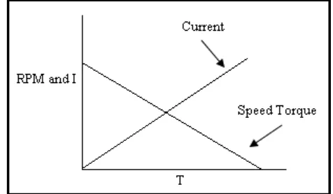
In DC motors of 0.1 horsepower (74.60 watts) or less, a permanent magnet field is most useful. Comparing motors below 1.25" in diameter, permanent magnet motors run cooler than wound field types because no power is expended to maintain a magnetic field. The permanent magnet field functions perfectly for thousands of hours of operation and lasts indefinitely on the shelf. Permanent magnet motors are easily reversed by changing the polarity of the voltage applied to the connecting terminals. They are capable of high-stall torque and function perfectly in long-duty cycle applications. Dynamic braking is easily obtained by merely applying a short circuit to the motor terminals after voltage is removed. With Globe permanent magnet motors, this usually results in less than 20 armature revolutions coast. Figure 1 illustrates a speed-torque/current-torque curve for a permanent magnet motor. Each curve is a theoretical straight line since the permanent magnet field and armature winding are constant in a
xxii
given motor. Current varies in proportion to torque, and the slope of this curve is a torque constant (KT) in oz. in./amp. [12]
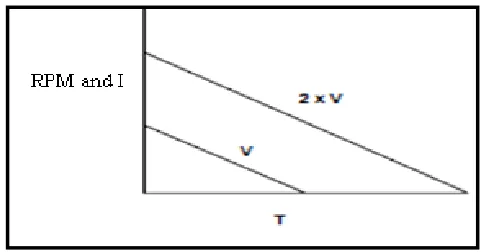
Figure 2.1 shows that with the permanent magnet motor, no load speed varies inversely with field strength and stall torque varies directly with field strength. In this illustration, curve “a” is the lowest value, curve “b” is the nominal and curve “c” is the maximum value of field strength. Figure 2.5.3 indicates the result of changing the applied voltage to a permanent magnet motor. No load speed changes proportionally to voltage, resulting in a family of parallel speed-torque curves. Remember that voltage determines speed, and only torque will determine current. [12]
Figure 2.1 Permanent Magnet Motor Curves
Figure 2.2 Speed Tolerance Characteristics
xxiii
Figure 2.3 Voltage Effect on Speed
2.6 DC MOTOR CONSTANT
Motor constants are parameters used to define motor characteristics. Torque constant (KT) and resistance (R)completely define a permanent magnet motor in terms of determining speeds, torques, efficiencies, currents, etc. DC motor brushes produce a non-linear voltage drop at the commutator somewhat similar to the forward voltage drop of a silicon diode. It is customary to add a 1- to 2-volt drop factor for this when calculating performance using KT and R. However, the KT and R values shown in this catalog are adjusted so that this is not necessary. Motor performance calculations for these motors will indicate actual performance when lead or terminal voltage is used and the torques are within the normal operating range of no load to one-half of stall. For motors 1.25" diameter and smaller, any errors out to stall should be less than 5%. At the power levels near stall on motors 1.50" and larger, both brush drop and field distortion due to input current are a much larger factor and actual torques near stall will be less than expected. In this catalog, all values of KT are in oz. in./amp. Conversion
to other units is as follows:
oz. in./amp x .706155 = Newton centimeters/amp oz. in./amp x 7.06155 = milli-Newton meters/amp
xxiv
oz. in./amp x 72 = gm cm/amp oz. in./amp x .0625 = lb. in. amp oz. in./amp x .0052 = ft. lbs./amp
The voltage constant KE in volts/1000 rpm is obtained from the equation KE =
KT/1.35. The motor constant . This constant is a measure of motor "size," but
for comparison be sure that equal units are used. Units will be torque/ while the physical realization of this constant is the stall torque at one watt input. The no-load-torque value shown in this catalog for each motor series includes all no load losses and can be considered a nominal value over the speed ranges where it is anticipated that the unit will be used. While brush and bearing friction are relatively independent of speed, other factors such as grease viscosity, wind age, hysteresis and electrical losses will change as exponential functions of speed. The most noticeable variation from unit-to-unit or test-to-test will be caused by temperature effects on grease viscosity. When more exact calculations are required, you may assume that one-half of the no load losses occurs at zero rpm and that these losses will follow a linear curve from this point to the listed catalog value at 8,000 rpm. KT and R values in this catalog are all nominal values at +25°C and should not be considered as minimum or maximum. [12]