ISSN: 2180-3811 Vol. 5 No. 2 July - December 2014 63
PREDICTION OF CUTTING FORCE IN
END MILLING OF INCONEL 718
M.S. Kasim1,*, C.H. Che Haron2, J.A. Ghani2, N. Mohamad1,
R. Izamshah1, M. Minhat1, S.B. Mohamed3, J.B Saedon4, N.H Saad4
1Faculty of Manufacturing Engineering,
Universiti Teknikal Malaysia Melaka, 76100 Hang Tuah Jaya, Melaka.
2Faculty of Engineering and Built Environment, Universiti Kebangsaan Malaysia, 43600 Bangi, Selangor.
3Faculty of Design and Engineering Technology, Universiti Sultan Zainal Abidin, Gong Badak 21300
Kuala Terengganu, Terengganu.
4Faculty of Mechanical Engineering, Universiti Teknologi MARA, 40450 Shah Alam, Selangor.
ABSTRACT
This paper presents the efect of cuting parameters on the cuting force when machining Inconel 718. Response surface methodology (RSM) was used in the experiment, and a Box–Behnken design was employed to identify the cause and efect of the relationship between the four cuting parameters (cuting speed, feed rate, depth of cut and width of cut) and cuting force. The ball-nose type of end mill with donwmill approach was maitained througout the experiment. The forces were measured using Kistler dynamometer during straight line machining strategy. The result shows that the radial depth of cut was the dominating factor controlling cuting force, it was followed by axial depth of cut and feed rate. The prediction cuting force model was developed with the average error between the predicted and actual cuting force was less than 3%.
KEYWORDS: Inconel 718; end mill; cuting force; response surface
method; perturbation plot; high-speed machining
1.0 INTRODUCTION
Inconel is well-known to be one of the hardest materials to be machined. Due to its stability during extreme temperature, it is widely used for applications requiring high temperature strength resistance (Kitagawa, et al., Ulutan & Ozel, 2011). As an example, more than ive hundred
ISSN: 2180-3811 Vol. 5 No. 2 July - December 2014 64
jet turbine engine element are fabricated using Inconel 718 (Kalluri & Halford, 1995). However, one of its limitation is poor machinability, which is due to high strength property and abrasive particle, causing short tool life (Sharman, et al., 2001). These problems are related to materials deformation and friction at vicinity region of tool-chip and tool-workpiece interface (Ezugwu, et al., 1999; Izamshah, et al., 2012). During machining of this material, the temperature rise leads to an increase in material’s toughness and thus increase in cuting force (Liao, et al., 2008). Studies by Ezugwu et al., (2005). Kitagawa et al., (1997). found that the cuter sufered in notch wear near DOC line during machining of Inconel 718. It was indicated that the notch wear started with piting and chipping on cuting edge due to interrupted cuting process. Kasim et al., (2013) found that the maximum force exerted onto rake face in the moment after tool engagement with the workpiece. The failure modes of laking on a rake face and notch wear on the lank face are associated with the combination of cyclic load and maximum force on the depth of cut (DOC) line. The result of these failures causes the cuting tool to fail catastrophically.
Design of experiment (DOE) is a systematic method to determine the relationship between uncontrollable inputs afecting the controlled output of the process (Montgomery, 2009). This statistical tool is widely used to replace time consuming trial and error basis. DOE helps to simplify to experimental process. A large number of studies have been conducted to determine the optimal machining process. As an example, Saedon et al., (2014) atempted a study on multi objectives optimization on WEDM of Ti6Al4V. The error between prediction and experimental of surface roughness was 2%. Amran et al., (2013) reported on surface roughness on drilling process. Based on their study in drilling process, the surface roughness was decreased as the spindle speed, feed rate and tool diameter increased. A mathematical model of surface inish during turning of Ti6Al4VELi was developed by Sulaiman et al., (2014). In their study, a statistical model was developed using RSM as to predict the cuting force during the milling process and identify the minimum cuting force. Here, it was observed that the occurrence of notch wear can be delayed and usable life of the cuting tool can be prolonged.
2.0 METHODOLOGY
ISSN: 2180-3811 Vol. 5 No. 2 July - December 2014 65
Table 1. Inconel 718 compositions.
Al B C Cb.Ta Co Cr Cu Fe Mn Mo
0.49 0.004 0.051 5.05 0.30 18.30 0.04 18.70 0.23 3.05
Ni P S Si Ti
53.0 < 0.005 < 0.002 0.08 1.05
The insert was coated with TiAlN/AlCrN multilayer PVD coating with WC-10% Co; 10 Ø mm; radial rake angle 0°; axial rake angle -3° and relief angle 11°. The milling operations were carried out on the DMC 635 V Eco CNC milling machine with a maximum speed of 8000 RPM. The cuting forces were measured using a Kistler model 5070 A dynamometer. The cuting parameters are cuting speed, feed rate, depth and width of cut. Accordance to Box-Behnken technique, the number of trials is 29 for four factors including 5 center points. The cuting force was recorded throughout single-pass cuter with the fresh cuting condition. The cuting parameter for this study is shown in Table 2.
Table 2. Experimental level of the independent variables and coding.
Factor\Level -1 0 1
Cutting speed, Vc (m/min) 100 120 140
Feed rate, fz(mm/tooth) 0.1 0.15 0.2
Depth of cut, ap(mm) 0.5 0.75 1.0
Width of cut, ae(mm) 0.2 1 1.8
3.0 RESULT AND DISCUSSION
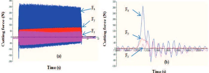
The measured cuting forces (Fx, Fy, Fz) are ploted in Figure 1a. For ball nose end milling, Fx is found to be dominating cuting force of 64%, followed by Fy (19%) and Fz (17%) as shown in Figure 1b.
ISSN: 2180-3811 Vol. 5 No. 2 July - December 2014 66
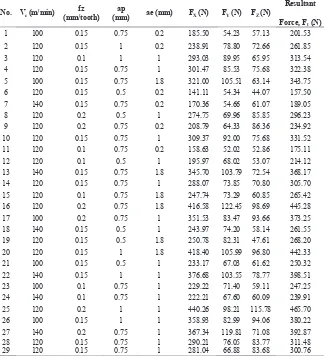
The resultant force, Fr , consisting of three major cuting-force component, Fx, Fy, Fz associated with the force direction of x, y, z axis respectively. This parameter is calculated by employing an expression as given in Equation (1) Alauddin, et al., (1996), with the results as listed in Table 3.
��=���+��+�� (1)
From the experimental results, it is apparent that ball nose end milling can achieve low cuting force which initiated from 157 N up to a maximum of 466 N. Similar indings were reported by previous work on milling of Inconel 718 Alauddin, et al., (1998a, 1998b, 1998c, 1998d).
Table 3. Cuting force results of diferent cuting conditions.
No. Vc(m/min)
ISSN: 2180-3811 Vol. 5 No. 2 July - December 2014 67
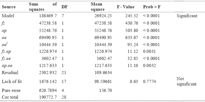
The analysis of variance (ANOVA) was applied to check the adequacy of the model and determine the signiicance of efects. From ANOVA analysis, as given in Table 4, the F-Value of 245.52 indicates that the model is signiicant. This is supported by the lack of it value of 0.63, which implies that the model is not signiicant. The Box-Behnken quadratic model shows that width of cut, ae, has the highest efect on
cuting force, followed by axial depth of cut, ap, and feed rate, fz. It was also observed that the cuting speed, Vc is not signiicant on the
exerted force. Therefore, this non-signiicant cuting parameter was removed from the model. This reduction of Vc term does not afect the
prediction model since the coeicient in model is too small which can be neglected. Furthermore, there is very marginal diference between R2 (0.987) and the adjusted R2 (0.984). These observations suggested that this model can be applied due to the lack of it probability model is 77.7%. Hence, the probability to be poor discrepancy between observed values and the values expected of the statistical model is very low.
Table 4. ANOVA for the second order model of cuting force.
Source Sum of
squares DF
Mean
square F- Value Prob > F
Model 188469.7 7 26924.25 245.52 < 0.0001 Significant
fz 47238.58 1 47238.58 430.76 < 0.0001
ap 55248.76 1 55248.76 503.80 < 0.0001
ae 69490.95 1 69490.95 633.67 < 0.0001
ae2 10444.39 1 10444.39 95.24 < 0.0001
fz.ap 1226.974 1 1226.974 11.12 0.0031
fz.ae 3602.47 1 3602.47 32.85 < 0.0001
ap.ae 1217.633 1 1217.633 11.10 0.0032
Residual 2302.932 21 109.6634
Lack of fit 1676.142 17 98.59661 0.63 0.7774 Not significant Pure error 626.7894 4 156.70
Cor total 190772.7 28
e (2)
2.1 Statistical equation model for resultant force
From the experimental results, a statistical equation model was developed to estimate the resultant force through all signiicant factors using normal model transformation. The resultant force, Fr, can be predicted by the following second-order model which shown in Equation (2):
ISSN: 2180-3811 Vol. 5 No. 2 July - December 2014 68
Fr=106.43 - 546.26 fz - 26 ap + 37.6 ae - 60.2ae2+ 1401.13 fz.ap+750.26 fz .ae+ 87.24 ap.ae (2)
where fzis feed rate, apaxial depth of cut and aeis width of cut. The comparison has
where fz is feed rate, ap axial depth of cut and ae is width of cut. The comparison has been made between actual and calculated value as shown in Figure 2, the average error for 29 trials being approximately 2.6%.
Figure 2. Experiment and calculation comparison with average error of 2.6%. 0
Figure 2. Experiment and calculation comparison with average error of 2.6%.
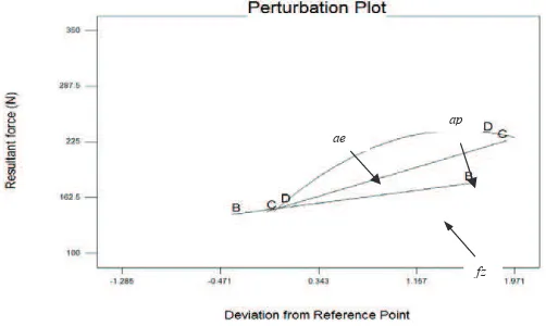
The optimum cuting parameters to obtain the lowest resultant force of 150.23 N were Vc = 125.7 m/min, fz = 0.12 mm/tooth, ap = 0.52 mm and ae = 0.22 mm. It is clearly presented in a perturbation plot in Figure 3 that the optimum value is achieved at the negative ends of every factor studied in this work. It shows positive response in reducing the resultant force which normally reduces the tool life in machining process. Besides, it is an interesting point to be noted that factor C and D would further decrease the optimum value for the minimum resultant force by shifting the factors to the lower ranges.
Figure 3. Perturbation plot of optimized cutting parameters.
fz ap ae
ISSN: 2180-3811 Vol. 5 No. 2 July - December 2014 69
3.0 CONCLUSIONS
This paper shows the relationship between cuting parameter and cuting force during end milling. A mathematical model based on RSM method has successfully been developed to calculate the resultant force. The prediction for resultant force largely agrees with the 29 series of experimental result. This study shows the cuting force can be signiicantly reduced by controlling width of cut. Width of cut, ae of 0.2 mm is suggested to minimize cuting force generated. The experiment shows the ball nose application able to reduce cuting force as low as 150 N.
ACKNOWLEDGEMENTS
Authors are grateful for the technical and inancial support provided by Universiti Teknikal Malaysia Melaka, Universiti Kebangsaan Malaysia and the Government of Malaysia for technical and inancial supports (Project No. LRGS/TD/2012/USM-UKM/PT/05 and PJP/2013/FKP(18A)/ S01276).
REFERENCES
Alauddin, M., El Baradie, M. A., & Hashmi, M. S. J. (1996). Modelling of
cuting force in end milling Inconel 718. Journal of Materials Processing Technology, 58(1), 100-108.
Alauddin, M., Mazid, M. A., El Baradi, M. A., & Hashmi, M. S. J. (1998). Cuting
forces in the end milling of Inconel 718. Journal of Materials Processing
Technology, 77(1-3), 153-159.
Alloys, N. S. (2011). 718 Inconel® Nickel Alloy Bar. Retrieved 3 March, 2011,
from htp://www.nsalloys.com/718-nickel-alloy-bar.html
Ezugwu, E. O., Wang, Z. M., & Machado, A. R. (1999). The machinability of nickel-based alloys: a review. Journal of Materials Processing Technology, 86(1-3), 1-16.
Izamshah, R., Mo, J. P. T., & Ding, S. (2012). Hybrid delection prediction on
machining thin-wall monolithic aerospace components. Journal of
Engineering Manufacture, 226(4), 592-605.
Kalluri, S., & Halford, G. R. (1995). Fatigue Behavior and Deformation Mechanisms in Inconel 718 Superalloy Investigated. Retrieved from
htp://www.grc.nasa.gov/www/rt/rt1995/5000/5220k.htm
Kitagawa, T., Kubo, A., & Maekawa, K. (1997). Temperature and wear of
cuting tools in high-speed machining of Inconel 718 and Ti6Al6V2Sn.
ISSN: 2180-3811 Vol. 5 No. 2 July - December 2014 70
Liao, Y. S., Lin, H. M., & Wang, J. H. (2008). Behaviors of end milling Inconel 718 superalloy by cemented carbide tools. Journal of Materials Processing
Technology, 201(1-3), 460-465.
Montgomery, D. C. (2009). Design and Analysis of Experiments (7th ed.). Hoboken: John Wiley & Sons, Inc.
Sharman, A., Dewes, R. C., & Aspinwall, D. K. (2001). Tool life when high speed ball nose end milling Inconel 718. Journal of Materials Processing
Technology, 118(1-3), 29-35.
Ulutan, D., & Ozel, T. (2011). Machining induced surface integrity in titanium and nickel alloys: A review. International Journal of Machine Tools &