UNIVERSITI TEKNIKAL MALAYSIA MELAKA
INVESTIGATION ON TOOL WEAR CHARACTERISTICS
WHEN MACHINING FC 300 GRAY CAST IRON WITH
UNCOATED CARBIDE FLAT END MILL
This report submitted in accordance with requirement of the Universiti Teknikal Malaysia Melaka (UTeM) for the Bachelor Degree of Manufacturing Engineering
(Manufacturing Process) (Hons.)
By
NURUL BAZILAH BINTI MOHD SABRI
B051110287
920913115040
1 Julai 2015
BORANG PENGESAHAN STATUS LAPORAN PROJEK SARJANA MUDA
TAJUK: INVESTIGATION ON TOOL WEAR CHARACTERISTICS WHEN
MACHINING FC 300 GRAY CAST IRON WITH UNCOATED CARBIDE
FLAT END MILL
SESI PENGAJIAN: 2014/15 SEMESTER 2
Saya NURUL BAZILAH BINTI MOHD SABRI
mengaku membenarkan Laporan PSM ini disimpan di Perpustakaan Universiti Teknikal Malaysia Melaka (UTeM) dengan syarat-syarat kegunaan seperti berikut:
1. Laporan PSM adalah hak milik Universiti Teknikal Malaysia Melaka dan penulis. 2. Perpustakaan Universiti Teknikal Malaysia Melaka dibenarkan membuat salinan
untuk tujuan pengajian sahaja dengan izin penulis.
3. Perpustakaan dibenarkan membuat salinan laporan PSM ini sebagai bahan pertukaran antara institusi pengajian tinggi. atau kepentingan Malaysia sebagaimana yang termaktub dalam AKTA RAHSIA RASMI 1972)
(Mengandungi maklumat TERHAD yang telah ditentukan oleh organisasi/badan di mana penyelidikan dijalankan)
Disahkan oleh:
Cop Rasmi:
Tarikh: _______________________
DECLARATION
I hereby, declare this thesis entitled ―INVESTIGATION ON TOOL WEAR CHARACTERISTICS WHEN MACHINING FC 300 GRAY CAST IRON WITH UNCOATED CARBIDE FLAT END MILL‖ is the results of my own research except as cited in the reference.
Signature : ………
Author Name : ………
Date : ………
APPROVAL
This report is submitted to the Faculty of Manufacturing Engineering of UTeM as a partial fulfillment of the requirements for the degree of Bachelor of Manufacturing Engineering (Manufacturing Process) (Hons.). The member of the supervisory is as follow:
i
ABSTRAK
ii
ABSTRACT
iii
DEDICATION
iv
ACKNOWLEDGEMENTS
Firstly, I would like to express my greatest gratitude to Allah SWT for giving me chances to explore and gain new knowledge throughout the period of completing my Final Year Project. I would also like to thank my family especially my beloved parents for their never ending support and courage in terms of financial and emotion as well as their prayers in order to provide me with better education for a better and brighter future.
Not to forget, millions of thanks I wish to my supervisor Dr. Mohd Hadzley bin Abu Bakar for his continuous guidance and support throughout my learning process and completing this study. I would also like to thanks each and every one in Faculty of Manufacturing Engineering; the lecturers, staffs and technicians for the cooperation in sharing their experiences and knowledge as well as their time and energy.
v
2.1.3 Factors Affecting Machining 8
vi
3.2 Work Material Selection 34
3.3 Cutting Tool Selection 34
3.4 Process Parameters 35
3.5 Machines and Equipment 36
3.5.1 3 Axis CNC Vertical Milling Machine 36 3.5.2 Wire Electrical Discharge Machining (WEDM) 37
3.5.3 Stereo Microscope 37
3.5.4 Scanning Electron Microscope (SEM) 38
3.6 Experimental Procedures 39
3.7 Analysis on Cutting Tool 39
4. RESULT AND DISCUSSION 40
4.1 Result of Tool Wear Measurement 40
4.2 Effect of Tool Life 44
4.3 Progression of Tool Wear at Several Interval Time 46
4.4 SEM Images of Cutting Tool 49
vii
5. CONCLUSION AND RECOMMENDATION 61
5.1 Conclusion 61
5.2 Recommendation 62
REFERENCES 63
APPENDIX
viii
LIST OF TABLES
2.1 Elements affecting machining operation 9
2.2 Values of hardness and tensile strength limits of FC 300 cast iron 31
2.3 General composition FC 300 cast iron 31
3.1 Cutting parameters 35
ix
LIST OF FIGURES
2.1 Deformation of material in machining 7
2.2 Chip flow in orthogonal and oblique cutting 8
2.3 Diagram of horizontal and vertical milling machines 11
2.4 CNC milling machine 11
2.5 End milling operation 12
2.6 Various types of end milling cutter 13
2.7 End mill with different flutes 13
2.8 General characteristics of cutting tool materials 14 2.9 The hardness of various cutting tool materials as a function of
temperature (hot hardness)
15
2.10 Microstructure of tungsten carbides 16
2.11 Classification of tungsten carbides according to machining application
17
2.12 Abrasion wear 18
2.13 Adhesive wear 19
2.14 Diffusion wear 20
2.15 Classification of tool wear on cutting tool 21
2.16 Flank wear and tool retreat 22
2.17 Flank wear on end cutting edge of end mill 23
2.18 Diagram of crater wear 24
2.19 Crater wear 24
2.20 Central wear 25
2.21 Evolution of the flank wear land vbb as a function of cutting time for different cutting speeds
26
2.22 Taylor tool life curve 27
2.23 Microstructures of several cast irons 28
2.24 Microstructure of gray cast iron 29
2.25 Typical microstructures of FC 300 gray cast iron 30
x
3.2 The main grey cast iron grades worldwide 34
3.3 Tungsten carbide with 2 flutes flat end mill cutter 35
3.4 Haas‘ 3 axis CNC vertical milling 36
3.5 MITSUBISHI RA-90 Wire Electrical Discharge Machining (WEDM) machine
37
3.6 Meiji Stereo Microscopes type EMZ 38
3.7 Zeiss SEM type Evo 50 Series 38
4.1 The effect of cutting time and spindle speed on tool wear 42
4.2 Graph of tool wear versus cutting time 42
4.3 Graph of tool life based on spindle speed 45 4.10 Image of flank wear using stereo microscope 52 4.11 The formation of built-up edge (BUE) during 4000 rpm (300X) 53 4.12 Adhered chips near the tool edge during 4500 rpm (300X) 53 4.13 A few adhered chips on tool face at 5000 rpm (300X) 54 4.14 Welded chips at tool face during 5500 rpm (300X) 55 4.15 Welded chips at tool face during 6000 rpm (300X) 55 4.16 Chipping occurred at flank edge during 4000 rpm machining 56 4.17 Edge fracturing during machining at 4000 rpm 57 4.18 SEM images of edge fracture at 5500 rpm from (a) top view (300X)
and (b) side view (500X)
58
4.19 SEM images of edge fracture at 6000 rpm from (a) top view (300X) and (b) side view (500X)
59
4.20 (a) Cutting edge of tool before machining, (b) Cutting edge of tool when machining at 4000 rpm, (c) Cutting edge of tool when machining at 6000 rpm
xi
LIST OF ABBREVIATIONS
ASTM - American Society for Testing and Materials
BUE - Built-Up Edge
ISO - International Organization for Standardization JIS - Japanese Industrial Standard
MMSB - Miyazu Malaysia Sdn Bhd Rpm - Revolution per minute
SEM - Scanning Electron Microscope WC - Tungsten Carbide
1
CHAPTER 1
INTRODUCTION
The introduction elaborates the main idea of the project whereas it introduces the title, the project background, objectives, problem statement and scope of the project. The specification of the study are enlighten in this chapter as guidance and information about this project.
1.1 Background of Project
In any industries involving manufacturing processes, machining is deemed to be the most important process since plethora of metal products have been produced by performing the machining process. In general, machining implicates a process of metal cutting or to be more specific, it may be defined as the material removal from the work piece. Since new innovation has been comprehensively developed in late decades, rather than customary machining, progressed machining has been took set which is more savvy, adaptable and high throughput assembling methods for delivering high exactness and superb discrete metal parts for the aviation, car, also die and mold production (De Ciurana et. al., n.d).
2
have numerous features incorporate gaps, spaces, pockets, and even three dimensional surface forms. Therefore, cutting tool is the most necessary tools in order to perform the milling operation. According to Schneider (2010), there are various types of cutting tool provided in respect to milling process. It is created in a wide size ranges to make milling a versatile machining process. Amongst them are end mill which is regarded as one of the indispensable tools in the milling processing. End mills are usually performed for facing, slotting and profile milling in order to produce flat and groove surface.
Despite of that, the application of milling process is broadly practiced in industry of making mold and die. Milling tools eliminate most of the material parts and then forming a work piece to a die or mold part. In addition, it is utilized in producing large and small die with variety features and complicated shapes. Basic examples include the milling of flat surface, indexing, gear cutting furthermore the cutting of spaces and key-ways.
In manufacturing of die, one of the materials used is FC300. FC300 is a type of gray cast iron used in metal cutting process. In FC300 manufacturing, there are many sub processes can be conducted for instance parting, slotting, grooving, flattening and curving. According to Tupy (n.d), the mechanical properties of the FC300 cast iron are depending on the metal matrix and graphite. Since it is iron with more refined graphite and totally pearlitic structure, giving it advantages on a better surface finish and a higher hardness. Meanwhile, it also good resistance to leaking since its properties can withstand to a high pressure and usually been used in production of valve bodies, heads, caps and plungers. FC300 cast iron specification is similar to ASTM A48, class 40 (Fujii et. al., 2009).
3
incredible wear resistance (Enco, n.d). However during machining FC300, it is still not well investigated the surface and tool wear characteristics.
Hence, this study will investigate the machining characteristics of FC300 when machining with uncoated carbide end mill. The focus of this study is to investigate the wear characteristics during machining with uncoated carbide flat end mill. The methodology that will be used to carry out this project is experimental procedures. In the experiment that is soon to be conducted, the tools have to undergo a machining test at various parameters before analysis can be done. The evaluation of machining performance of the cutting tools mentioned above is depends on the tool wear and tool life and being examine using scanning electron microscopy (SEM).
1.2 Problem Statement
In any manufacturing process, tool wear is undesirable and hard to be prevented. Parameters incorporate cutting speed, feed rate, tool material, cutting depth, coolant and work piece may impact the machining execution and tool life (Anlagan, 2005). Amid machining, cutting tool is normally exposed to high temperature, contact stresses and sliding along the tool-chip interface and along the machined surface. As a consequence, tool wear will arise and adversely affected the machining performance (Kalpakjian and Schmid, 2001).
4
not been well investigated. Therefore, this study will involve the research regarding the wear mechanism and tool life by varying the cutting speeds when machining FC300 gray cast iron with uncoated carbide end mill.
1.3 Objective of Project
The specific objectives for analysis performance of uncoated carbides flat end mill in milling with FC 300 gray cast iron in this project are:
(a) To evaluate the tool life of uncoated carbide cutting tool according to cutting parameter when machining FC 300 gray cast iron.
(b) To examine the type of failure modes when machining FC 300 gray cast iron according to the view angle.
(c) To analyze the mechanism of wear when machining FC 300 gray cast iron with uncoated carbide flat end mill.
1.4 Scope of Project
5
CHAPTER 2
LITERATURE REVIEW
This chapter elaborates the meanings and information regarding the project where it informs on the details of the project. The idea, data and information are collected from various resources in order to understand the concept and useful information or knowledge for the project.
2.1 Machining
Machining is very practicable to extensive range of work materials and frequently utilized to metals. On the other hand, it can be described as a process to remove excess material in the form of chips that could be achieved by a sharp cutting tool in purpose of to obtain the desired shape (Molian, 2006). Pursuant to Ruiz 2007, variety of part shapes and special geometry features can be produced by machining as well as giving a good result in term of dimensional accuracy and surface finish.
Even though, most machining obliges low set-up expense contrasted with forming, molding, and casting processes but for high volumes, it is substantially more expensive. Machining is fundamental where tight tolerances on dimensions and finishes are required. In addition, Madraj (2001) had stated that machining likewise covers a few processes, which can be partitioned into the accompanying classes:
6
(b) Non-traditional processes have various energy forms other than sharp cutting tool to remove material.
(c) Advanced machining processes that utilize electrical, chemical, thermal, and hydrodynamic methods, as well as lasers.
(d) Cutting includes single point or multipoint cutting tools with a clearly defined tool shape.
2.1.1 Elements of Machining
According to Kalpakjian and Schmid (2001), there are several primary elements in the following below that are required for a machining process.
(a) Work piece: Its shape and size for continuous and intermittent cutting, the chemical composition, mechanical properties and metallurgical properties.
(b) Tool: Material and geometry
(c) Chip: Types of chips and their geometry
7
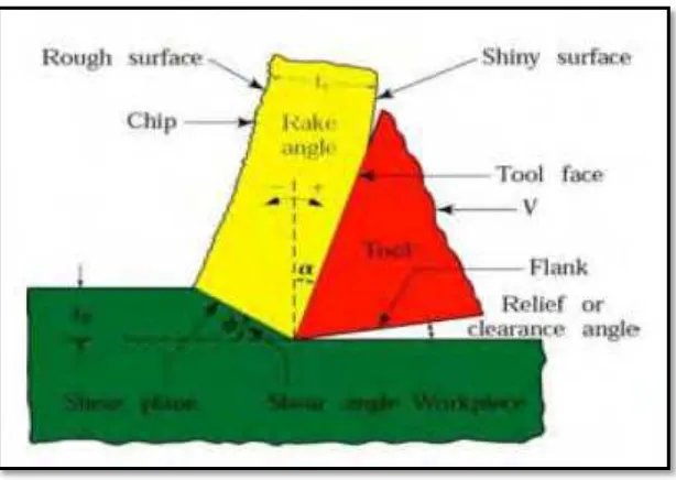
Figure 2.1: Deformation of material in machining (Ruiz, 2007).
Figure 2.1 shows a schematic illustration to represent the nomenclature of the machining process. The undeformed chip thickness t1 is the value of the depth of cut, while t2 is the thickness of the deformed chip after leaving the work piece. The major deformation starts when the cutting tool, in a rake angle, α, shears the metal to form an angle of shear, Ø, at a specific cutting speed, V, and feed rate, f. The deformed chip is separated from the parent material by fracture to remove the excess stock of the parent material to create a finished work piece of the required dimensions (Schneider, 2005).
2.1.2 Classical Metal Machining Process
8
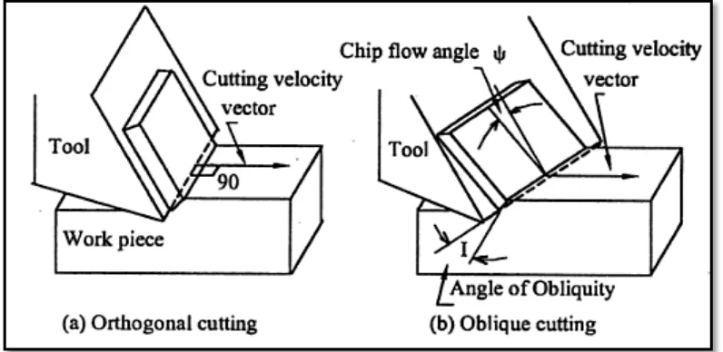
Figure 2.2: Chip flow in orthogonal and oblique cutting (Juneja and Seth, 2003).
Krar and Check (1997) had differentiated the orthogonal cutting with oblique machining in their book based on approach angle. In orthogonal cutting, the approach angle is 90° while oblique machining describes the process when the approach angle is not equal to 90°.
In spite of that, Junega and Sekhon (2003) additionally guaranteed that the cutting edge of the tool in orthogonal cutting is perpendicular to the cutting speed direction. Then in sideways cutting, the angle between the cutting edge and cutting velocity is not quite the same as 90° and the cutting edge of the tool is not perpendicular to the cutting velocity however set at angle with the normal to the cutting velocity. Also, Rajput (2007) had effectively investigated the contrasts in the middle of orthogonal and oblique cutting in term of tool life. In his findings, he identified that oblique cutting is more efficient since its tool life is higher than orthogonal cutting.
2.1.3 Factors Affecting Machining
9
cutting process. Amongst them are (i) tool material and coatings, (ii) tool shape, surface finish and sharpness, (iii) work piece material and condition, (iv) cutting speed, feed and depth of cut, (v) cutting fluid, (vi) features of the machine tool as well as (vii) work holding and fixturing.
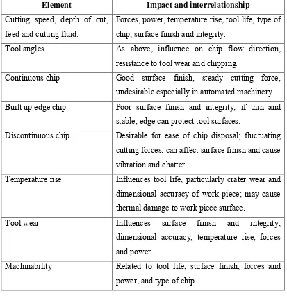
On the contrary, dependent variable is comprises of factors that may be influenced by changes. The examples of dependent variable include (i) type of chip produced, (ii) force and energy dissipated during cutting, (iii) temperature rise in the work piece, the tool and the chip, (iv) tool wear and failure and also (v) surface finish and surface integrity of the work piece. Table 2.1 shows elements that affecting machining operation.
Table 2.1: Elements affecting machining operation (Kalpakjian and Schmid, 2010).
Element Impact and interrelationship
Cutting speed, depth of cut, feed and cutting fluid.
Forces, power, temperature rise, tool life, type of chip, surface finish and integrity.
Tool angles As above, influence on chip flow direction, resistance to tool wear and chipping.
Continuous chip Good surface finish, steady cutting force, undesirable especially in automated machinery. Built up edge chip Poor surface finish and integrity; if thin and
stable, edge can protect tool surfaces.
Discontinuous chip Desirable for ease of chip disposal; fluctuating cutting forces; can affect surface finish and cause vibration and chatter.
Temperature rise Influences tool life, particularly crater wear and dimensional accuracy of work piece; may cause thermal damage to work piece surface.
Tool wear Influences surface finish and integrity, dimensional accuracy, temperature rise, forces and power.